
Plane Talk: SR Batteries Eindecker E I
Paul Vliet
THE FOKKER Eindecker E.I, better known as the "Fokker scourge" in World War I, and its French counterpart the Morane-Saulnier were among the first to be designated "fighter" aircraft. They were leaders in the use of forward-firing machine guns that were capable of shooting through the arc of the propeller via the use of a synchronizing mechanism.
Aircraft preceding these initially carried observers with rifles or pistols and then machine guns that had restricted fields of fire. Air-to-air combat was limited before the introduction of these two designs.
Anthony Fokker incorporated a few innovations into his aircraft's production that were not used on the Morane-Saulnier, one of which was a welded steel-tube airframe. It significantly increased strength and rigidity compared to the standard wood airframes that were contemporary for the time.
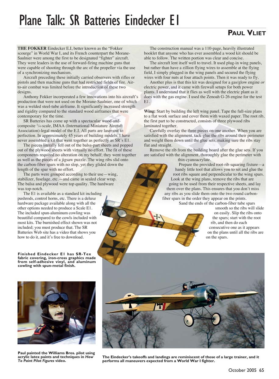
SR Batteries has come up with a spectacular wood-and-composite 1/4-scale, IMAA (International Miniature Aircraft Association)-legal model of the E.I. All parts are laser-cut to perfection. An approximately 45 years of building models, I have never assembled a kit that went together as perfectly as SR's E.I. The pieces literally fell out of the balsa-part sheets and popped out of the plywood sheets with virtually no effort. The fit of the components required no alteration on my behalf; they went together as well as the pieces of a jigsaw puzzle. The wing ribs slid onto the carbon-fiber spars with no slop, yet they glided down the length of the spar with no effort.
The parts were grouped according to their use—wing, stabilizer, fuselage, etc.—and came in sealed clear wrap. The balsa and plywood were top quality. The hardware was top-notch.
The E1 is available as a standard kit including pushrods, control horns, etc. There is a deluxe hardware package available along with all the other options needed to produce a Scale E1. The included spun-aluminum cowling was beautiful compared to the cowls included with most kits. The burnished effect shown was not included; you must produce that. The SR Batteries Web site has a video that shows you how to do it, and it's free to download.
The construction manual was a 110-page, heavily illustrated booklet that anyone who has ever assembled a wood kit should be able to follow. The written portion was clear and concise.
The aircraft lent itself well to travel. It used plug-in wing panels, but rather than have a zillion flying wires to assemble at the flying field, I simply plugged in the wing panels and secured the flying wires with four nuts at four attach points. Then it was ready to fly.
Another plus is that this kit was designed for a gas/glow engine or electric power, and it came with firewall setups for both power plants. I understand that it flies as well with the electric plant as it does with the gas engine. I used the Zenoah G-26 engine for the test E1.
Wing: Start by building the left wing panel. Tape the full-size plans to a flat work surface and cover them with waxed paper. The root rib, the first part to be constructed, consists of three plywood ribs laminated together.
Carefully overlap the three pieces on one another. When you are satisfied with the alignment, tack-glue the ribs around their perimeter and weight them down until the glue sets, making sure the ribs stay flat and straight.
Remove the rib from the building board after the glue sets. If you are satisfied with the alignment, thoroughly glue the perimeter with thin cyanoacrylate.
Prepare the provided root-rib squaring fixture—a handy little tool that allows you to set and glue the root ribs square and perpendicular to the wing spars. Look at the wing plans, remove the ribs that are going to be used from their respective sheets, and lay them over the plans. This ensures that you don't miss any ribs as you slide them onto the two round carbon-fiber spars in the order they appear on the prints.
Sand the ends of the carbon-fiber tube spars smooth so the ribs will slide on easily. Slip the ribs onto the spars; start with the root rib, and then do each consecutive one as it appears on the plans until all the ribs are on the spars. Set the 1/4 balsa shim under the block at the tip in the place indicated by the plans to create the required amount of wing washout. Weight everything in place to keep the parts from moving.
Using the squaring fixture you constructed, set over the top of the forward spar and up against the root rib, adhere the root rib to the carbon-fiber spars with thin cyanoacrylate. After gluing the root rib to the spars, use the two comb-type rib spacers provided in the kit to properly space the rest of the ribs.
Cyanoacrylate-glue the ribs to the spars and move the comb down the wing. Attach it to the last rib adhered and then to the unglued ribs. Cyanoacrylate-glue those ribs in place on the spars, and move the combs again until all the ribs are glued in place.
It's time to add the LE spar. Make some paper-clip/rubber-band clamps as illustrated in the construction manual. Snap the carbon-fiber LE into place and hold it there with the clamps, and then cyanoacrylate-glue the LE to the ribs.
Add the LE and TE doubler to the wing panel. These are the two 1/8 balsa pieces that are tapered on the ends and cap the ribs where the ailerons attach.
Glue in the hinge-mounting blocks. There are two pieces for each of the five bays, and they are precut to fit. Glue the top strip in the notches at the rear of the ribs where the ailerons go, and that completes the construction of the "aileron drag spars," as they are called in the manual.
Glue the aircraft-plywood servo mounts between ribs R-4 and R-5. Assemble the actual servo mounts to the servo bay door. Set the servo door in place and make sure it fits properly.
Prepare the mounting plates for the flying wires. The plates are constructed from three pieces of plywood with a center-section that tab-locks into a wing rib. Clean out laser screw holes before gluing the pieces together. I used a 7/64 Allen wrench to ream out the holes.
Install the eight anchor plates in the wing panel per the prints. Glue in the precut plywood wingtip formers. Add the balsa tip-thickening plates and the top and bottom tip ribs, and round the tip to the proper shape.
Assembling ailerons is next. Position the 1/8 balsa TE over waxed paper-covered plans. Glue the first plywood rib at the inboard end of the aileron. Use the aileron control-horn mounting plates to set the spacing for the second plywood rib. Use the plywood comb, as before, to space the rest of the aileron ribs.
Glue in the TE doubler. Glue in the aileron control-horn plate. Install the plywood aileron tip plate, note that it is not glued flush with the building board on the LE but has to be shimmed up 1/8 inch on the LE. Glue on the upper balsa tip plate.
Pluses and Minuses
- Extreme accuracy of laser-cut parts and kit quality.
- Four full-size, color-coded blueprints.
- Ease of construction and installation of radio gear.
- Instruction manual's clarity and attention to detail.
- Model's high strength with use of carbon-fiber spars in wing LE, horizontal stabilizer LE, and elevators' TEs.
- Flying wires should have turnbuckles incorporated into system for adjustability.
- Tedious assembly of landing-gear system (although it is explained well in instruction manual).
Stabilizer and Elevators: The horizontal stabilizer LE and elevator TE are made from 1/4-inch round carbon fiber (CF). This greatly increases strength and accuracy while decreasing these edges' "dingability."
Cover the plans with waxed paper. Laminate the horizontal stabilizer tips by adding the balsa parts to the plywood centers. Round over the LE tabs on the stabilizer tips so they can be inserted into the CF LE. Laminate the stabilizer TE. Insert the tips' LE tabs into the CF LE tube and the rear tabs into the slot in the TE.
The entire assembly locks together fairly well without glue. Place it over the plans, glue the tips to the LEs and TEs, and add the ribs.
Laminate the wider center ribs. These will fasten to the fuselage when the horizontal stabilizer is installed. These ribs have to be fish-mouthed to fit around the 1/4-inch CF LE.
To make this job easier, cut a V-shaped notch in the rib LE with a scroll saw. Round it out by wrapping sandpaper around the actual spar and using it as a sanding tool.
Laminate the elevator tips and the LE, placing the shorter LE piece in the center of the lamination. Slide the tip LE tabs into the LE and the TE tabs into the 1/4-inch CF TE. Set the assembly over the plans and add the ribs. Sand the horizontal stabilizer and the elevators to their final shape. Bevel the LE of the elevators from the top and bottom to a horizontal centerline. Fit the elevator control horns.
Rudder: Remove the plywood core from the sheet and place it over waxed paper-covered plans. Weight it down to keep it straight. Make note of the balsa part numbers that will be laminated to the rudder core. They are numbered on the plans relating to where they go on the rudder.
Lay all the parts for the perimeter of one side of the rudder in place where they go. Glue them to the core one piece at a time. Add the inner structure parts and then flip the rudder to the other side and repeat the process.
Position the piece of 1/4-inch CF tube, left over from the construction of the horizontal stabilizer, in the center slot of the rudder. When you have the tube equidistant from each side and protruding approximately 1/16 inch from the bottom of the slot, tack-glue it in place.
Check the positioning of the tube. If you are satisfied with its placement, glue it in place with thick cyanoacrylate on both sides using kicker and the glue in sort of a caulking method. Block-sand the tube flush with the bottom of the rudder. Sand the rudder to final shape.
Fuselage: Laminating the firewall begins the fuselage construction. The firewall consists of three pieces laminated together. There are two light-plywood layers precut for different power-plant setups; one is for electric and one is for gas/glow.
Use the layer that matches your power plant as the top piece in the stack, the one that doesn't match in the center, and the aircraft-plywood piece on the bottom. Use slow-setting epoxy to laminate the layers.
Prepare the longerons. They are made from 7/8 spruce lengthened through a wood-joining method long known to boat builders as "scarfing." With this technique you join two pieces of wood by cutting the ends of both on a long matching angle.
Overlap the ends of each piece to be joined by approximately 1 1/2 inches. Spot-glue the pieces together, one on top of the other, at the 1 1/2-inch overlap. Use a razor saw to slice through both pieces at the same time, cutting on as long an angle as is allowed by the overlap. This will result in a joint that has a perfectly matched custom angle on each piece. Glue the two scarfed ends together and trim away the scrap material.
Cover the plans with waxed paper. Glue one of the fuselage side doublers to the fuselage side using the scrap pieces of wing spar to align the holes in the doubler with the holes in the fuselage side. Repeat for the opposite side of the fuselage, taking care not to make two rights or two lefts. Add the balsa chin doublers.
It's time to install the longerons. Glue the bottom longeron in place over the plans, taking care to match the angle of the joint between the longeron and the chin doubler. Glue the top longeron, placing the scarf joint over the top of the plywood fuselage side. Repeat this process for the opposite side.
Place the left side of the fuselage directly over the plans, and make sure it is in perfect alignment with them. Bring the longerons together at the tail, mark them according to the plans, and cut them to length. To bring the longerons into alignment at the tail, you need to cut the inside corners off so they will fit together tightly. Temporarily join the ends of the longerons over the plans.
Glue in the stabilizer support plate flush with the upper surface of the longerons (the side not against the plans). Use two layers of 1/8 balsa scrap to shim the stabilizer mounting plate up to the surface. Make sure everything is lined up according to the plans and glue the support plate to the longerons.
Cut the first upright to length using 1/4 square spruce. Cut it to the length on the plans and not to the space between the longerons. Remove it and add the precut gussets to the longerons, and then glue the upright to the longerons and the gussets. Repeat this process for the other uprights. Add the four special gussets at the fuselage sides and then add the 1/8-inch square diagonal braces.
Turn the left fuselage side over so the plywood side is against the table with the longerons facing up, and cover the entire side with waxed paper. Lay the right side over the top of the left side, longeron against longeron, and align the plywood sides on top of one another. Pull the longerons on the upper fuselage half over the ones on the lower half and pin them together.
Add the stabilizer support plate, gussets, uprights, and diagonals just as you did for the first half.
Separate the fuselage halves and add the stabilizer-mount doublers to the inside of the support plates. Use a straightedge to project the top and bottom lines of the stabilizer through the end of the longerons. Trim the longerons so that the stabilizer will be able to slide into the fuselage when it’s completed.
Add the forward servo mounting-plate reinforcement to the forward underside of the servo mounting plate. Trial-fit the servo tray in place in each fuselage side. Trial-fit the two formers into both fuselage sides along with the servo tray.
Lay the right side of the fuselage on the table, and dry-install the formers and the servo tray. Set the left side in place over the formers and servo tray, and weight them in place.
Use a carpenter’s square to check the alignment of the longerons of both sides with one another at the tail. If they are not square, move the upper set of longerons at the tail up or down until they are square. Glue the formers and servo tray to the lower fuselage half.
Install the bellcranks per the plans in the 3/8-inch square uprights at the end of the plywood sides. Install the uprights. Drill a hole in the center of the upper servo-tray reinforcement and install the rudder bellcrank.
Install the firewall with epoxy, and glue in the 3/8-inch square hatch support to the underside of the firewall. Cut and fit the 1-inch square balsa stock in the corners where the fuselage sides meet the firewall. To save weight, I cut the square stock into triangle stock. Epoxy these pieces to the firewall and sides.
Install the bottom plywood sheathing to the underside of the fuselage starting at the rear. Add the rear main gear support and then the rear piece of sheathing over the top of it. Use the gear to set a space between the rear piece of sheathing and the center piece, thus ensuring that the landing-gear wire will fit in the slot.
Use the center piece of sheathing to mark the position of the forward main gear support, and glue the forward gear support in place. While maintaining the rear 7/32-inch gap, glue the center piece of sheathing in place. Add the third piece of sheathing, maintaining the 7/32-inch gaps at both landing-gear slots to accommodate the wire landing gear.
Use the gear wire as a spacer to set the slot at the proper width. Add the upper and lower 1/8 light-plywood sheathing. The upper piece is the one with four slots in it for the rudder and elevator pull-pull cables.
Add the upper and lower crossmembers, gussets, and diagonal braces according to the prints. Leave out the upper and lower diagonal braces just aft of the fuselage sides until after the pull-pull cables are installed.
Install the pull-pull cables to the bellcranks and route them through their proper slots per the plans. Leave plenty of excess cable outside the slots and tape it to the sheathing so that it doesn’t get in the way. Crimp all the bellcrank connectors at this time per the instructions.
Add the balsa sheathing that runs between the firewall and the plywood landing-gear plate. Prepare and install the fuel-tank support. Add the lower firewall support block.
Construct the cheek cowls and sand them to final shape according to the plans. I did not install the cheek cowls until the wing was in place. This allowed for exact placement of the cheek cows around the wing. Construct the hatch per the plans and trial-fit it on the fuselage.
Mount the engine cowl. Find the top center of the cowl and the top center of the firewall. Drill a 1/16-inch hole at the center screw location 1/2 inch in from the rear of the cowling.
Slip the cowl in place on the firewall and locate the centerline on the firewall through the hole you just drilled in the cowl. Drill it with the 1/16-inch bit to a depth of 1/2 inch and install a 5/64 socket-head screw provided. Remove the screw and cowl, and put a few drops of thin cyanoacrylate in the hole. Reinstall the screw after the cyanoacrylate has cured to clean up the threads. Reinstall the cowl with the center screw.
Locate and install the other cowl screws, making sure the holes fall into the center of the firewall. You may need to trim roughly 1/2 inch off the edges of the firewall to keep it even with the bottom of the firewall. You can do this with a pair of tin snips.
Engine Mounting: The firewall is predrilled if you are using one of the recommended power plants. I chose the Zenoah G-26 engine.
Mount the engine of your choice and then install the throttle servo mount and the throttle pushrod, but don’t glue it in place yet. I didn’t permanently install these parts until after the covering process.
A-Frame Installation: It is easiest to apply whatever finishes you plan to use on the hatch now. It is much easier to drill a hole in the finish for the “A” frame than it is to finish around it. Install the “A” frame according to the instructions.
Sand the steel wires before covering them with the copper-wire wrap. Lightly sand the copper-wire wrap; it is usually finished with a varnish to prevent oxidation. If you do not sand the copper, it will result in a poor solder joint that will turn black because the solder won’t flow. Use soldering paste over the joint to be soldered.
Landing-Gear Construction: This aircraft’s landing gear is unique. It and the tail skid are designed to withstand quite a bit of shock; both incorporate elastic cord to help with shock absorption.
Build the landing gear per the instructions. The step-by-step detail is excellent. Use the soldering techniques I described to attain strong solder joints. The landing-gear wires are pre-bent and fit together well. Use the fuselage upside-down in a cradle as a fixture. The tail skid is constructed from leftover ends from the 3/8 spruce spars.
Final Assembly: Cut all the hinge slots in all the control surfaces, elevator, ailerons, and rudder. Dry-fit everything and check the fit.
It is time to cover the model. I used the recommended SR Batteries’ Antique SR-Tex fabric and was happy with the results.
Mount and align the horizontal stabilizer per the manual. Prepare and mount the rudder center post and support wires, making sure the post is square to the plane of the horizontal stabilizer before cementing it in place.
Mount the tail skid. Trim the rudder post so the rudder has the proper clearance when set in place over the rudder post.
Install the rudder and elevator control horns. Hinge the elevators to the horizontal stabilizer. Hinge the ailerons to their respective wing panels. Reinstall the engine and throttle servo. Install the fuel tank and fuel-line system.
Install the elevator and rudder servos, along with the radio receiver and all its components, switches, etc. Turn on your transmitter and receiver, and center the servos.
Install the servo control arms, and set up and install the pushrods that go between the servo arms and the bellcranks on the rudder and on each elevator servo, making sure that the bellcrank arms are set to a neutral position with the radio turned on. Install the pull-pull cables on their respective control horns, again while the radio is turned on, thus assuring that the control surfaces stay in the neutral position when the cables are installed under tension.
Final adjustments can be made to the control surfaces by adjusting the fittings between the bellcranks and the servo arms. Try to be as close to neutral as possible when hooking up the cables so you don’t exceed the limits of the pushrod servo control and cause binding.
Install the wing panels on the fuselage with the aileron servos, extension leads, etc. already in place. Plug in the aileron servos and install the aileron pushrods.
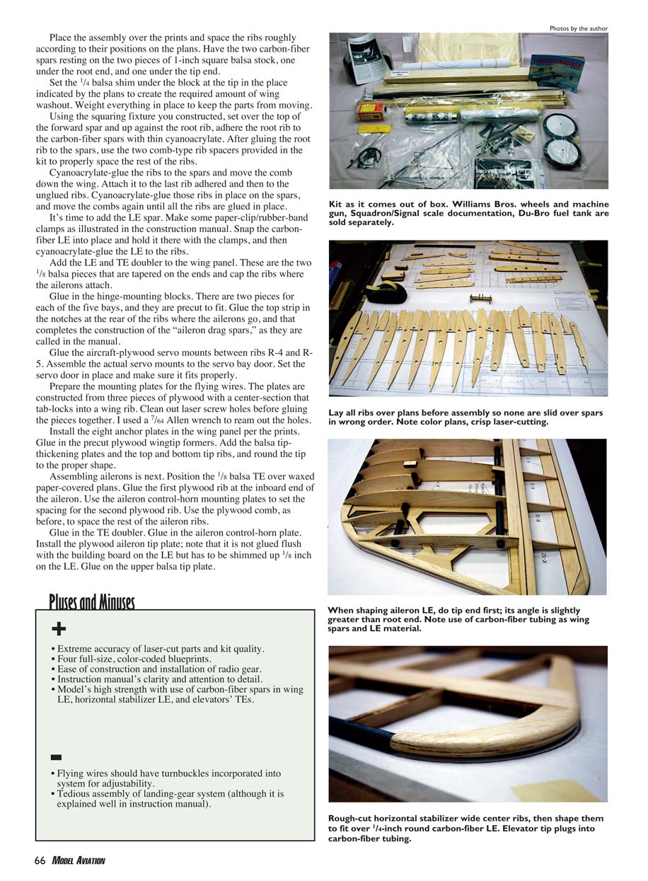
I painted the pilot figure I purchased from SR Batteries with methods described in the How to Paint Pilot Figures video by Don Tyondd. The tape is available from Robin’s View Productions, Box 68, Stockertown PA 18083; Tel.: (610) 746-0106. I highly recommend this video. Techniques described in it can provide almost anyone with the skills needed to produce outstanding pilot figures.
Follow the instructions and install the upper and lower flying wires. Install the upper wires first, making sure to set the wing dihedral with the upper wires per the instructions. Install the lower wires, and that's it. We're ready for the model's first flight.
Flying: My friend Woody Haggerty performed my Eindecker's test flight. I had every intention of doing the honors myself, but my photographer forgot to show up and I was the only one at the field who was capable of taking the flight photos.
After standard preflight checks for control-surface-throw direction, radio range check, etc., it was time to get this model airborne and see what it was capable of.
Ground handling could be a bit touchy, especially with tail skid vs. a steerable tail wheel in windy weather. To make the model turn on the ground, it was necessary to apply a blip of down-elevator with the rudder hard over in the direction of the turn while gunning the throttle. Straight ground travel was not a problem.
The takeoff run was no different than with any other tail-dragger. Woody applied the throttle slowly to full power while carrying a bit of right rudder to counteract the engine torque. As the tail came off the ground, he applied a little pressure on up-elevator until airborne. The Eindecker lifted off gently at slightly better than half throttle.
Once airborne, it was necessary to apply quite a bit of right trim to the rudder and ailerons to attain level flight. Upon landing and a closer inspection of the wing at a distance (impossible in the shop), it was obvious that I had put a warp in the wing with the flying wires. The warp was easily removed by adjusting the cables. The second flight was fine, and the trim levers were back to the center position.
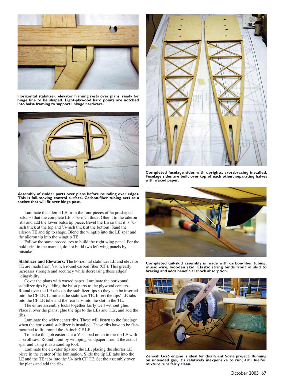
After attaining the proper setup and trim, the aircraft flew like a dream. Hands-off flight in a fairly stiff breeze was no problem. The aircraft flew scale-like at approximately half to two-thirds throttle.
As with a full-scale aircraft, it turned much more efficiently using a coordinated turn (rudder and ailerons in the same direction) than using only the ailerons in a crank-and-bank fashion. The rudder is an effective all-flying surface with no hinges.
Landing the Eindecker was as easy as, or maybe easier than, landing a trainer. Woody lined it up with the runway, cut the throttle to roughly one-third, and allowed it to sink. He cut the throttle to a high idle when over the threshold and started the flare. The high engine idle kept the elevator effective and helped overcome the flying wires' drag. The Eindecker slowed to a crawl and settled in for a great landing on the mains. If you are landing in the wind, you will need to keep your throttle a bit higher.
This aircraft is a terrific choice for a first-time Giant Scale-model builder. Its flight characteristics are gentle, yet it is capable of all the scale maneuvers one would expect from the full-scale World War I fighter. The Zenoah gas engine is a joy to work with and inexpensive to run.
SR Batteries went overboard on every aspect of this model. The design efforts were outstanding, incorporating many laminated and interlocking parts that add much to its strength and lightness. The laser-cut parts were outstanding. All the stick joints in the fuselage incorporated precut plywood gussets to increase their strength.
The SR-Tex was extremely easy with which to work. The company will sell you a foot of it or enough to cover the entire aircraft.
SR Batteries can set up a package that will include everything from a G-26 engine, to Giant Scale servos and extension leads, to the laser-cut vinyl graphics, painted or unpainted scale pilot figure, and anything else it takes to complete your Eindecker in a scale fashion, including aircraft documentation. Great job, SR Batteries!
Specifications:
Type: RC Giant Scale Pilot skill level: Intended for intermediate pilots Wingspan: 100 inches Wing area: 1,700 square inches Length: 67 inches Ready-to-fly advertised goal weight: 16 pounds, 8 ounces Review model's ready-to-fly weight: 16 pounds, 13.5 ounces Recommended engine: 1.20-1.80 two-stroke, 120-220 four-stroke, or 23-26cc gas Engine used: Zenoah G-26 Recommended radio: Four- to six-channel (minimum), five heavy-duty servos Construction materials: Light plywood, balsa, spruce longerons, carbon-fiber tubing for LE and spar material, aluminum cowl, music-wire landing gear, coated steel wire cable for flying wires
Manufacturer/Distributor:
SR Batteries, Inc. Box 287 Bellport NY 11713 (631) 286-0069 [email protected] www.srbatteries.com
Products used in review:
Zenoah G-26 engine: Horizon Hobby Distributors 4105 Fieldstone Rd. Champaign IL 61822 www.horizonhobby.com
Transcribed from original scans by AI. Minor OCR errors may remain.

