
Plane Talk: Hangar 9 Fokker D.VII ARF
By Jay Smith
Many consider the Fokker D.VII to be the finest single-seat fighter of World War I. Reinhold Platz designed the aircraft, and the Red Baron—Manfred von Richthofen—flew the prototype in January 1918. It soon entered service in May 1918, and more than 1,700 had been built by the end of the war.
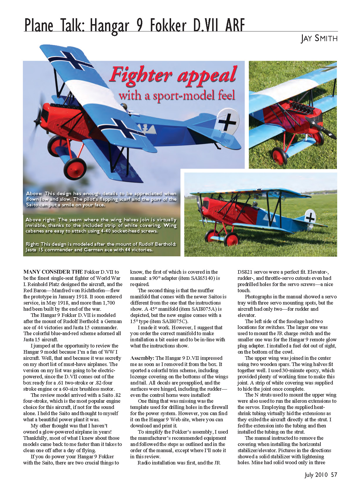
The Hangar 9 Fokker D.VII is modeled after the mount of Rudolf Berthold, a German ace of 44 victories and Jasta 15 commander. The colorful blue-and-red scheme adorned all Jasta 15 aircraft.
I jumped at the opportunity to review the Hangar 9 model because I'm a fan of WW I aircraft. The version I wanted was going to be electric-powered, since the D.VII comes out of the box ready for a .61 two-stroke or .82 four-stroke engine or a 60-size brushless motor. The review model arrived with a Saito .82 four-stroke, which is the most popular engine choice for this aircraft—if not for the sound alone. I held the Saito and thought to myself what a beautiful power plant it was.
My other thought was that I haven't owned a glow-powered airplane in years. Thankfully, most of what I knew about those models came back to me faster than it takes to clean one off after a day of flying.
Powerplant compatibility — two crucial things
- A 90° adapter (item SA165140) is required (this is covered in the manual).
- The muffler manifold that comes with newer Saito engines is different from the one shown in the instructions. The manual depicts a 45° manifold (item SA18075A), but newer engines come with a 15° type (item SA18075C). I made it work, but I suggest ordering the correct manifold to make installation easier and to match the manual.
Assembly
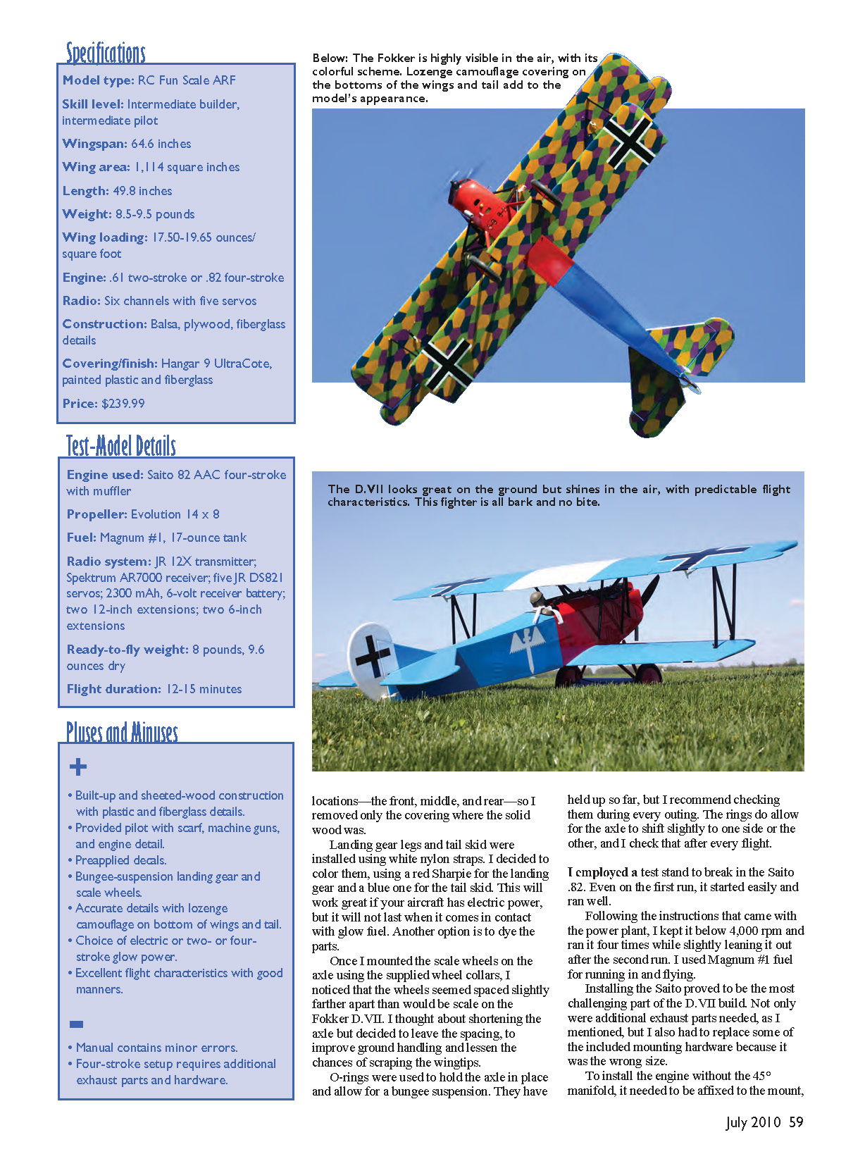
The Hangar 9 D.VII impressed me as soon as I removed it from the box. It sports a colorful trim scheme, including lozenge covering on the bottoms of the wings and tail. All decals are pre-applied, and the surfaces were hinged, including the rudder—even the control horns were installed.
One missing item was the template used for drilling holes in the firewall for the power system. You can download and print it from the Hangar 9 website.
To simplify the Fokker's assembly, I used the manufacturer's recommended equipment and followed the manual's steps and order, except where noted below.
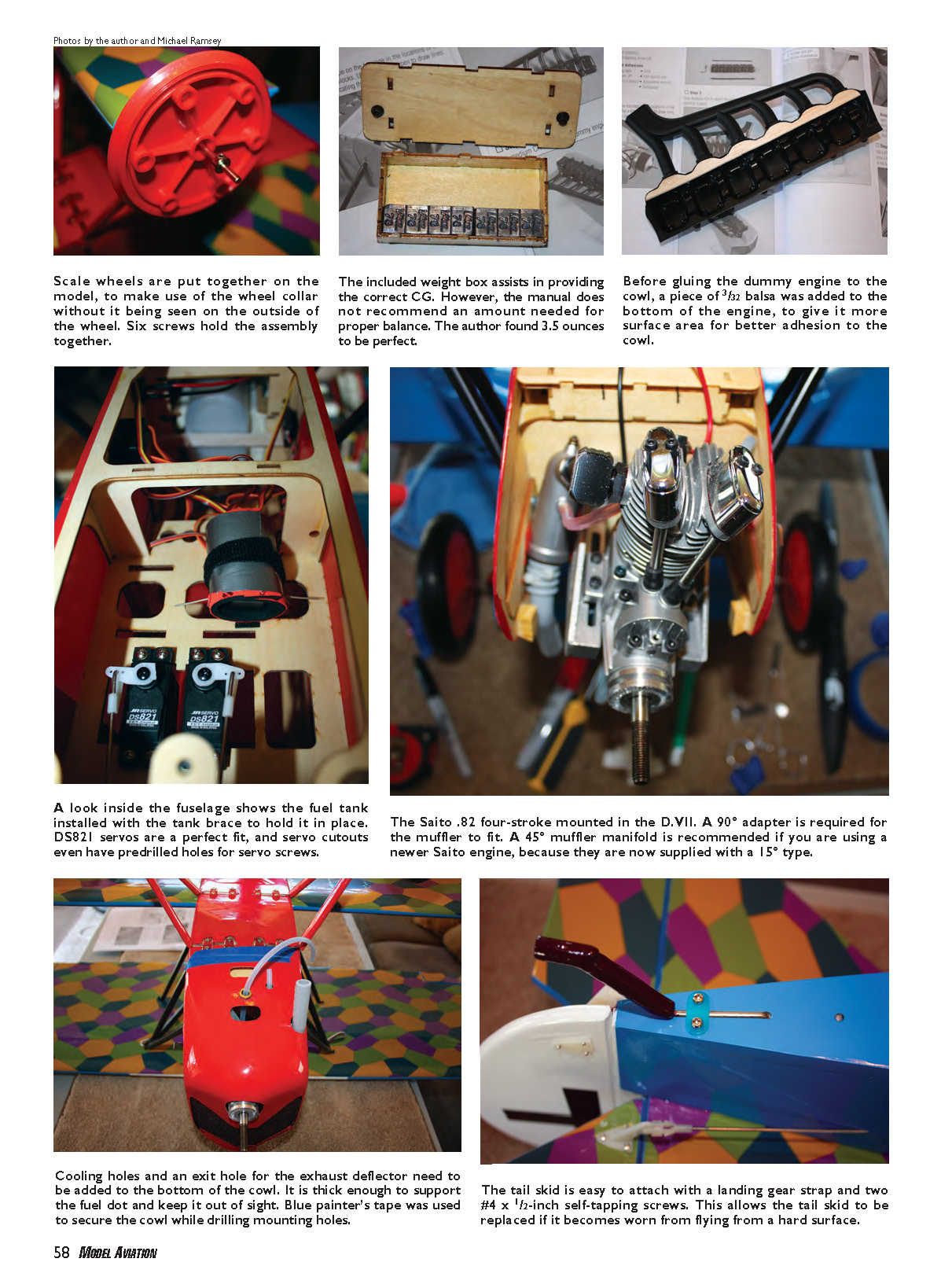
Radio installation was first. JR DS821 servos were a perfect fit. Elevator-, rudder-, and throttle-servo cutouts even had predrilled holes for the servo screws—a nice touch. Photographs in the manual showed a servo tray with three servo mounting spots, but the aircraft had only two—for rudder and elevator.
The left side of the fuselage has two locations for switches. I used the larger opening for the JR charge switch and the smaller one for the Hangar 9 remote glow plug adapter. I installed a fuel dot out of sight on the bottom of the cowl.
The upper wing is joined in the center using two wooden spars. The wing halves fit together well. I used 30-minute epoxy, which provided plenty of working time to make the joint. A strip of white covering was supplied to hide the splice joint once complete.
The N-struts used to mount the upper wing also serve to run the aileron extensions to the servos. Using the supplied heat-shrink tubing virtually hid the extensions as they exited the aircraft directly at the strut. I fed the extension into the tubing and then installed the tubing on the strut.
When installing the horizontal stabilizer/elevator, the manual instructs to remove covering where the solid wood is. The directions show a solid stabilizer with lightening holes; my stabilizer had solid wood only in three locations—the front, middle, and rear—so I removed only the covering where the solid wood was.
Landing gear legs and the tail skid attach with white nylon straps. I colored the straps with Sharpies—red for the landing gear and blue for the tail skid—which works for electric models but will not last with glow fuel exposure. A better option for glow models is to dye the parts.
Once I mounted the scale wheels on the axle using the supplied wheel collars, I noticed the wheels were spaced slightly wider than scale. I considered shortening the axle but decided to leave the spacing to improve ground handling and reduce the chance of scraping the wingtips. O-rings are used to hold the axle in place and allow for a bungee suspension. They have held up so far, but check them before every outing, as the axle can shift slightly to one side.
I used a test stand to break in the Saito .82. Even on the first run it started easily and ran well. Following the engine instructions, I kept it below 4,000 rpm and ran it four times, slightly leaning it out after the second run. I used Magnum #1 fuel for running in and flying.
A look inside the fuselage shows the fuel tank installed with the tank brace to hold it in place. Cooling holes and an exit hole for the exhaust deflector need to be added to the bottom of the cowl. The cowl is thick enough to support the fuel dot and keep it out of sight. Blue painter's tape was used to secure the cowl while drilling mounting holes.
The tail skid is easy to attach with a landing gear strap and two #4 x 1/2-inch self-tapping screws, allowing the tail skid to be replaced if it becomes worn from flying from hard surfaces.
Installing the Saito .82
Installing the Saito proved to be the most challenging part of the build. In addition to the manifold difference mentioned earlier, I had to replace some included mounting hardware because it was the wrong size.
- The engine requires the 90° adapter (SA165140).
- The newer Saito came with a 15° manifold (SA18075C) while the manual shows a 45° manifold (SA18075A). I recommend ordering the manifold that matches your engine or the one shown in the manual.
To install the engine without the 45° manifold, the engine needed to be affixed to the mount before the mount was bolted to the firewall. I used a Dremel tool to give the muffler slightly more room inside the fuselage.
The 8-32 hardware provided with the kit was too large to fit through the mounting lugs, so I replaced the supplied screws with 3.5 mm hardware rather than enlarging the holes. The 8-32 x 1-inch bolts used to attach the mount to the firewall were too long and protruded past the blind nuts; they would have contacted the fuel tank. I replaced them with 3/4-inch bolts.
A weight box is supplied to add nose weight. I attached the box behind the engine using two 4-40 screws. The manual gives no recommendation for the amount of weight needed; I found 3.5 ounces to be perfect.
The instructions show installing the dummy engine before the cowl, but I highly recommend installing the cowl first. The dummy engine was made from brittle plastic and had to be trimmed with a nibbler tool because hobby scissors caused small cracks. Installing the exhaust stack on the dummy engine was easiest by gluing one attachment at a time. To better glue the dummy engine to the cowl, I cut a piece of 3/32-inch balsa and added it to the bottom of the dummy engine to increase the bonding surface.
Aligning the cowl was hardest at the rear onto the 1/16-inch support on the fuselage. I used scrap balsa to make 45° ramps to guide it, which worked well.
Flying the Fokker
I set all control throws and exponential per the manual. The CG was exactly 3 5/8 inches behind the leading edge of the top wing near the cabane struts.
I set up an aileron/rudder mix that can be switched on and off via the transmitter. That way, if I was uncomfortable making coordinated turns manually, I could use the radio to help.
Using a grass runway because of the tail skid, the model taxied reasonably well with full up-elevator to keep the tail down. A 180° turn on the ground was a bit difficult.
With the D.VII facing into the wind, the Saito purred gently. Takeoff required slight up-elevator and rudder work to stay straight down the runway—much like full-scale WW I airplanes. Within about 30 feet the model was airborne, and a few clicks of trim yielded excellent handling.
Low-rate settings allowed the aircraft to be flown in a scale manner and perform lazy aerobatics comfortably. High rates were enjoyable and manageable for more aggressive flying. The aileron/rudder mix helped make coordinated turns but wasn't required; the model turns on ailerons alone without a noticeable loss of altitude.
Approximately half throttle was enough to cruise, and brief power bursts were used for vertical maneuvers. After some relaxed camera passes, I pushed the model harder—keeping in mind I was flying a WW I biplane—and it performed well.
The model was capable of loops, rolls, and stall turns; it tracked well and responded promptly to inputs. One of the most impressive characteristics was its stall performance: with throttle cut and full up-elevator the nose stayed up for a respectable amount of time. The stall warning was a gentle break to the left before falling off; recovery was easy.
Landing is best done into the wind. In a light crosswind the effective rudder helps. The airplane slowed nicely and had good glide performance—so good that a pilot might overshoot a first approach. To avoid overshooting, maintain a bit of throttle on final to keep airflow over the control surfaces. Once on the ground, pull back smoothly on elevator to plant the tail and use ailerons as needed to keep the wings level during rollout.
Throughout flying, I was impressed with the Fokker's predictable flight characteristics. It had the realistic look and sound of a WW I fighter with the manners of a sport aircraft.
The Saito .82 was a great match: it provided ample power and an unmistakable sound similar to the Mercedes and BMW engines in full-scale Fokkers. That, along with the fighter's cool factor, made it worth the time and expense of the cleaning supplies needed to fly it.
MA
Jay Smith [email protected]
Transcribed from original scans by AI. Minor OCR errors may remain.

