
Plane Talk: Cosmic Wind Little Toni ARF
Paul Vliet
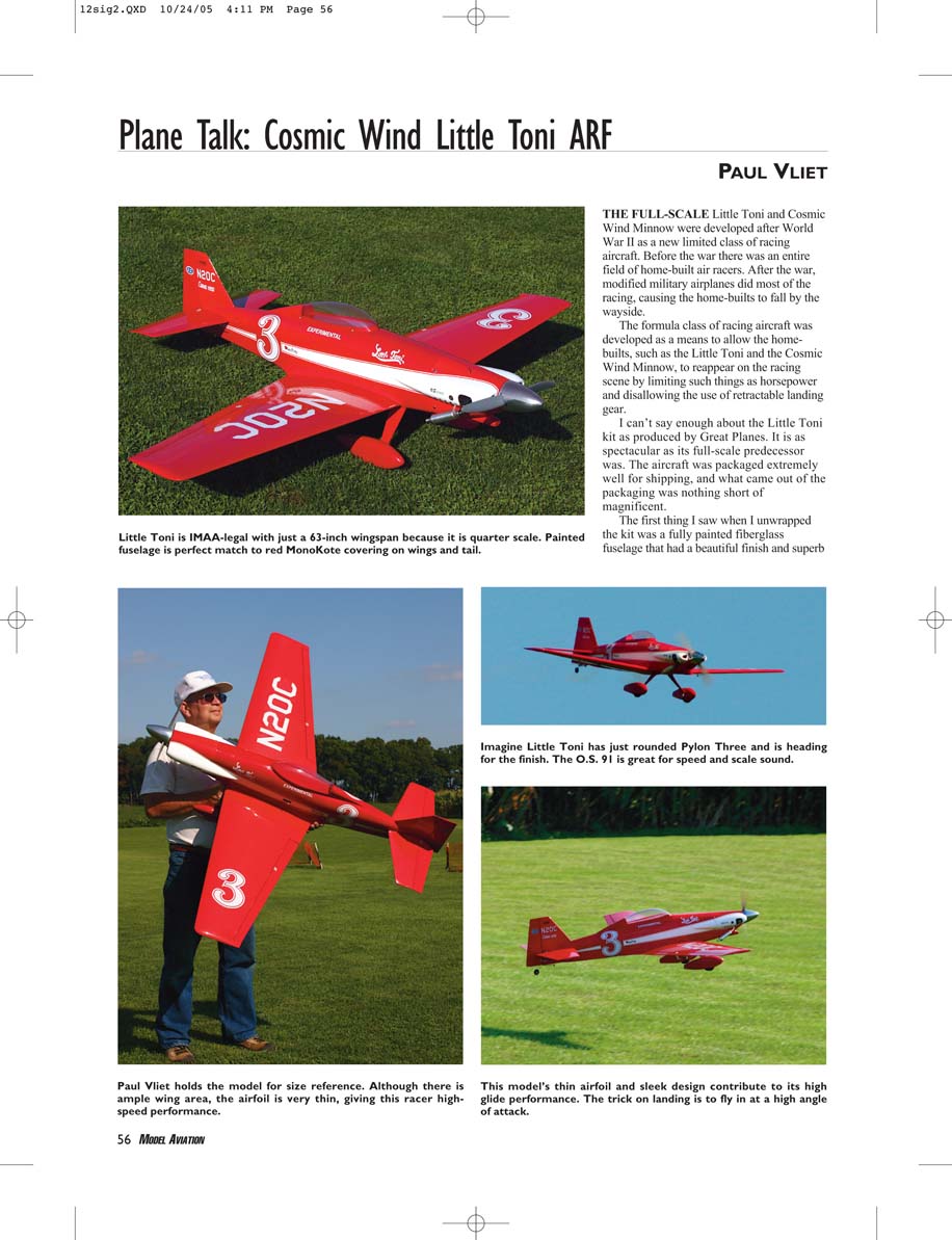
THE FULL-SCALE Little Toni and Cosmic Wind Minnow were developed after World War II as a new limited class of racing aircraft. Before the war there was an entire field of home-built air racers. After the war, modified military airplanes did most of the racing, causing the home-builts to fall by the wayside.
The formula class of racing aircraft was developed as a means to allow the homebuilts, such as the Little Toni and the Cosmic Wind Minnow, to reappear on the racing scene by limiting such things as horsepower and disallowing the use of retractable landing gear.
I can't say enough about the Little Toni kit as produced by Great Planes. It is as spectacular as its full-scale predecessor was. The aircraft was packaged extremely well for shipping, and what came out of the packaging was nothing short of magnificent.
The first thing I saw when I unwrapped the kit was that the kit was a fully painted fiberglass fuselage that had a beautiful finish and superb fiberglass work. The fiberglass cowling, with its rather complex shape, was also impressive.
The MonoKote-covered surfaces had a few bags or sags and took little effort (10–15 minutes) with an iron to correct. The hardware package was complete, and the instruction manual was detailed without being long-winded.
Wing Construction
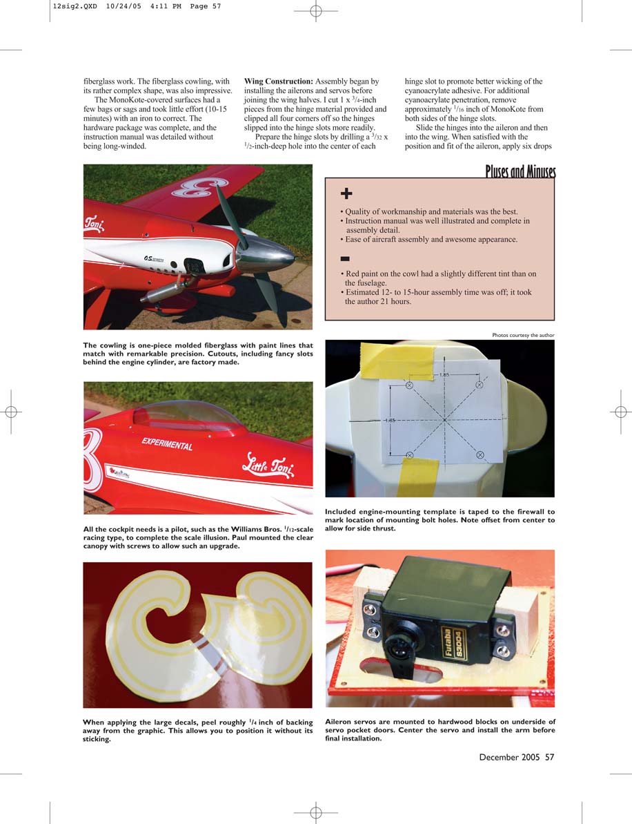
Assembly began by installing the ailerons and servos before joining the wing halves. I cut 1 x 3/4-inch pieces from the hinge material provided and clipped all four corners off so the hinges slipped into the hinge slots more readily.
Prepare the hinge slots by drilling a 3/32 x 1/2-inch-deep hole into the center of each hinge slot to promote better wicking of the cyanoacrylate adhesive. For additional cyanoacrylate penetration, remove approximately 1/16 inch of MonoKote from both sides of the hinge slots.
Slide the hinges into the aileron and then into the wing. When satisfied with the position and fit of the aileron, apply six drops of thin cyanoacrylate to each hinge area and allow to cure. After the adhesive fully cured, remove the aileron and final-trim the hinge material where necessary. Fit and mount the ailerons to the servos, and check for full, free movement without binding.
The wings join together with the supplied dihedral brace and bolts. Dry-fit everything first, then use epoxy to secure the dihedral brace in place. Install the wing hold-down dowels and bolts per the instructions, making sure the wing incidence is correct before final tightening.
Install the servos by fastening the provided hardwood blocks to them. I held the hardwood block in place under the servo mounting holes with the servo on its side on a flat work surface and marked the mounting holes on the blocks, then I drilled 1/16-inch holes in the blocks for the servo mounting screws. Then I mounted the blocks to the servo.
I set the entire assembly in place on the underside of the servo bay door, marked the servos' positions, and epoxied them in place. I installed a metal screw from the outside of the bay door, through, and into the hardwood blocks on each block.
I installed the servos and aileron extension wires into the wings. Mount the aileron control horns and the aileron pushrods, and the individual wing panels are complete.
Locate the main hardwood wing joiner (a slightly V-shaped piece of wood) and prepare to epoxy the wing halves together. Test-fit the two panels with the joiner in place.
Look for complete mating of the two root ribs along the top and bottom surfaces and the joiner in place and one panel sitting on a flat surface with the other panel shimmed up so that its wingtip is approximately 6 inches off the table.
I weighted the panel on the table to keep it from moving. Notice the position of the shim along the raised wing panel so you can put it back in the same position after you reapply the glue.
Take everything apart and apply 30-minute epoxy to the entire surface of both root ribs and to the surface of the hardwood joiner and the pockets that it goes into. Reassemble everything, but watch for excess glue that oozes from the joint. Wipe it off and clean the surface on the top and bottom of the wing with denatured alcohol on a paper towel or rag.
Pull the surfaces together tightly with long strips of masking tape and recheck for oozing glue; clean up as necessary. You have a fair amount of time with 30-minute epoxy to clean and tape the joint. Reset the one panel on the table and rest the shim on the other panel. Make sure the wingtip is still the required 6 inches off the table. I allowed the assembly to cure overnight.
Locate the 1/8 plywood rear wing joiner and set it in place over the wing bolt holes on the bottom of the wing. Mark the joiner's perimeter on the bottom of the wing and remove the MonoKote from this area.
I used a Weller soldering iron that has an attachment for holding and heating a pile of thin cyanoacrylate, using an applicator tube, to the top and bottom of each hinge. Do not use accelerator. Test the hinge by pulling on the aileron after the cyanoacrylate has cured.
Tail Assembly
The tail surfaces are pre-hinged and fit well. A small amount of sanding and a straightedge check ensured proper alignment. The tail-mounting screws and blind nuts were straightforward to install, and the elevator and rudder pushrods required only minor bending to achieve proper geometry.
Slide the horizontal stabilizer into the slot provided in the fuselage. Use care; I learned that it is a tight fit. Measure the distances from the wingtips to the corners of the horizontal stabilizer as depicted in the instruction manual.
Measure the distance, side to side, from the center of the vertical stabilizer to the tip of the horizontal stabilizer on each side, and make sure they are equidistant. The method shown in the manual is good and accurate.
Use a sharp pencil or fine-point pen to mark the fuselage line on the surface of the horizontal stabilizer when you are satisfied with its position. Remove the stabilizer and remove the covering between the marks.
Reinstall the stabilizer and make sure it is in exactly the same position as before by remeasuring. Use thin cyanoacrylate with an applicator tube to glue it in place.
Install the tail-wheel bracket. Dry-fit it in place on the vertical stabilizer and fit the rudder to it, making sure the top and bottom of the rudder are in alignment with the top of the vertical stabilizer and the bottom of the fuselage with the tail-wheel bracket in place.
Install the rudder and elevator halves per the instruction manual.
Bolt the landing gear to the fuselage using the four 8-32 x 3/4-inch flathead bolts provided. Cut the axles to the specified length and grind a flat spot on the end for the wheel collars.
When you install the wheels, slip on the inner wheel collar, the wheel, and then the outer wheel collar, leaving the inner collar loose until you lock the outer collar down flush with the very end of the axle.
Set the wheel against the outer collar and then bring the inner collar up against the wheel. This will allow the proper space for the wheel-pant mounting bolts to clear the tires. Mount the axles, wheels, and wheel pants.
The wheel pants are factory-set for the proper angle with the blind nuts installed—a nice touch. Simply bolt them in place and move on to installing the tail wheel.
Engine Installation
The firewall is laminated plywood and very stout. The included engine-mounting template made laying out the bolt holes simple. I offset the engine slightly to provide the recommended right thrust and used the engine box to align everything before final tightening. The cowl fit was excellent, with neat cutouts around the engine cylinder and muffler.
I used the O.S. 91 Surpass on the test model. The manufacturer recommends a four-stroke oil for this type because it fits the cowl well.
I started by darkening the molded-in engine-mount centering lines on the firewall with a fine-point Sharpie marker. I cut the engine-mount template from the instruction manual, centered it over the marks on the firewall, and taped it in place. I drilled the four engine-mount holes in the firewall using a 3/16-inch bit.
Install the four 8-32 blind nuts in the firewall from the back side using the 4-40 threaded rod provided. Slip a 4-40 nut on the threaded end of the rod and then slide an 8-32 blind nut on the rod with the teeth facing away from the nut.
Slip the rod through one of the 3/16-inch holes, and pull the blind-nut teeth into the wood of the firewall hard enough to make the blind nut stay in place. Gently remove the threaded rod.
Thread the 8-32 bolt with a washer into the partially set blind nut from the outside of the firewall, being careful not to dislodge the blind nut. Tighten the bolt until the blind nut is fully seated in the firewall, and repeat this process for the other three blind nuts.
Install the engine mount to the firewall, but do not completely tighten the bolts at this time. Set your engine in place on the mount, space the arms on the engine mount according to the width of your engine, and then tighten the mounting bolts.
The O.S. 91 fits perfectly inside cowling; running it has been trouble-free. Beefy nylon engine mounts included are strong and lightweight.
Scale aluminum spinner is included.
Radio/Servos
I used three Futaba S3003 servos for the ailerons and elevator and a sturdy S3002 for the rudder. The servos were mounted on hardwood blocks glued into the servo pockets for a secure installation. All linkages were set up with Du-Bro ball links for positive, slop-free control.
The receiver and four-cell battery pack were located in factory-recommended locations. Balance was perfect.
Final Setup
Control throws were kept conservative for the first flights — about 12 degrees on ailerons and elevator and 20 degrees on the rudder — until I had time to feel the model’s response. Balance is critical; the recommended CG was a good starting point, and with the installed OS .46 engine the model balanced right on the dot.
Use a standard 600 mAh battery pack in the location shown with servos and pushrods installed per the manual, and your model should balance perfectly. I set all control-surface throws per the manual for high and low rate.
Flight Impressions
The Little Toni is a delight to fly. Takeoff is smooth and the aircraft tracks straight and true. Rolls are crisp and axial; the little wing imparts excellent aileron authority. Loops are round and predictable. Landing is straightforward — a little power, flare, and she settles in nicely.
Test Flights: The Little Toni's test flights were awesome! It flew as great as it looked. After a few minor ground adjustments to the radio equipment, range-checking the radio, double-checking the control-surface throw directions, and checking the engine carburetor settings, it was time for the maiden flight.
The model's ground-handling characteristics could not have been better. It taxied straight. The takeoff roll was arrow straight and required only minimum right rudder until airborne, indicating that the factory-preset right thrust was spot on. The airplane required a slight amount of down-trim when I first went to level flight.
After a few passes to get a feel for the airplane, it was time to see what it could do. I put it into a vertical climb, and with the 91 Surpass at full throttle the airplane went to vertical until I pulled the throttle off. It climbed straight with a bit of right rudder applied.
I tried several loops and found that the Little Toni's tracking was excellent. Then I tried an Avalanche, and the inside snap at the top was scalelike and predictable—not too fast and not too slow.
The aircraft did not like Four Point Rolls very much. It tended to pull toward the belly in knife-edge flight. Inverted flight was stable and required a minimum of down-elevator to maintain a level attitude.
Landings took a little practice to get a feel for the best method to make the aircraft touch down. In addition to being streamlined, the airplane builds light and therefore has a tendency to want to keep flying on flare, especially if there is any wind. And the landing gear seems a little springy.
I found that the best landing tactic is to flare the model to a level position with the throttle closed and go to neutral elevator as soon as the wheels touch down; the wheels dragging on the runway bleed off airspeed. Slowly feed in up-elevator after the aircraft slows to keep it from nosing over.
I highly recommend this aircraft. It was a joy to assemble and an even greater joy to fly.
Even though the manufacturer estimates that it would take the average builder 10-15 hours to completely assemble the Little Toni, it took me 21 hours. The reason is probably that since I was building the airplane for review, I went over and examined many of the construction and fabrication aspects. Doing this slows me down a bit, but hey! That's my job.
I suspect that if my time were spent just building, I would have been done much quicker and the result would be the same great-flying airplane. Happy flying!
Paul Vliet [email protected]
Manufacturer:
Great Planes Model Manufacturing Co. Box 9021 Champaign IL 61826 (217) 398-8970 www.greatplanes.com
Pluses and Minuses
- Quality of workmanship and materials was the best.
- Instruction manual was well illustrated and complete in assembly detail.
- Ease of aircraft assembly and awesome appearance.
- Red paint on the cowl had a slightly different tint than on the fuselage.
- Estimated 12- to 15-hour assembly time was off; it took the author 21 hours.
Specifications
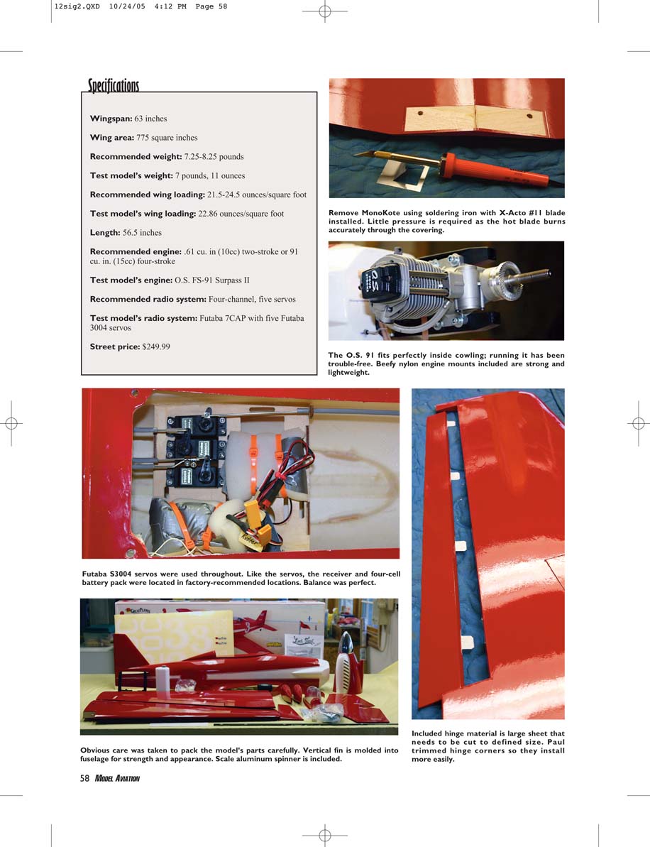
Wingspan: 63 inches
Wing area: 775 square inches
Recommended weight: 7.25-8.25 pounds
Test model’s weight: 7 pounds, 11 ounces
Recommended wing loading: 21.5-24.5 ounces/square foot
Test model’s wing loading: 22.86 ounces/square foot
Length: 56.5 inches
Recommended engine: .61 cu. in (10cc) two-stroke or .91 cu. in. (15cc) four-stroke
Test model’s engine: O.S. FS-91 Surpass II
Recommended radio system: Four-channel, five servos
Test model’s radio system: Futaba 7CAP with five Futaba 3004 servos
Street price: $249.99
Remove MonoKote using soldering iron with X-Acto #11 blade installed. Little pressure is required as the hot blade burns accurately through the covering.
Futaba S3004 servos were used throughout. Like the servos, the receiver and four-cell battery pack were located in factory-recommended locations. Balance was perfect.
Obvious care was taken to pack the model’s parts carefully. Vertical fin is molded into fuselage for strength and appearance.
Included hinge material is large sheet that needs to be cut to defined size. Paul trimmed hinge corners so they install more easily.
Transcribed from original scans by AI. Minor OCR errors may remain.

