
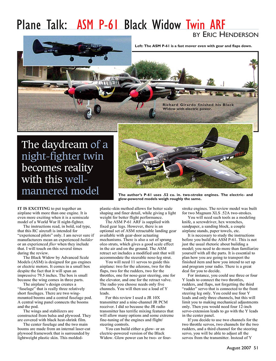
Plane Talk: ASM P-61 Black Widow Twin ARF
BY ERIC HENDERSON
The daydream of a night-fighter twin becomes reality with this well-mannered model
It is exciting to put together an airplane with more than one engine. It is even more exciting when it is a semiscale model of a World War II night-fighter.
The instructions read, in bold red type, that this RC aircraft is intended for "experienced pilots" only. I am never sure if manufacturers mean an experienced builder or an experienced flier when they include that. I will touch on this several times during the review.
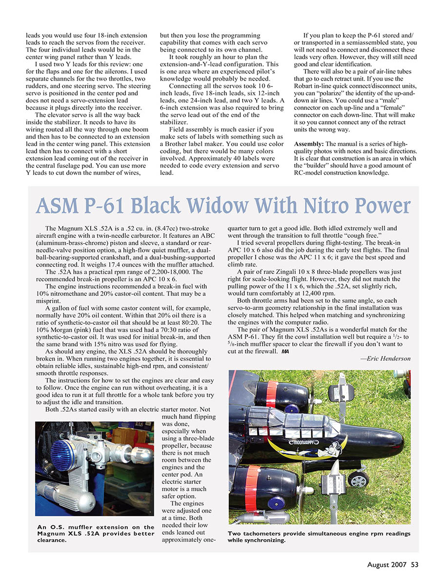
The Black Widow by Advanced Scale Models (ASM) is designed for gas engines or electric motors. It comes in a small box despite the fact that it will span an impressive 79.5 inches. The box is small because the wing comes in three parts. The airplane's design creates a "fuselage" that is really three relatively short fuselages. There are two wing-mounted booms and a central fuselage pod. A central wing panel connects the booms and the pod.
The wings and stabilizers are constructed from balsa and plywood and are covered with black heat-shrink film. The center fuselage and the two main booms are made from an internal laser-cut plywood framework that is surrounded by lightweight plastic skin. This molded-plastic-skin method allows for better scale shaping and finer detail, while giving a light weight for better flight performance.
The ASM P-61 ARF is supplied with fixed gear legs. However, there is an optional set of ASM retractable landing gear available with gear-door actuating mechanisms. There is also a set of sprung oleo struts, which gives a good scale effect in the air and on the ground. The ASM retract set includes a modified unit that will accommodate the steerable nose-leg strut.
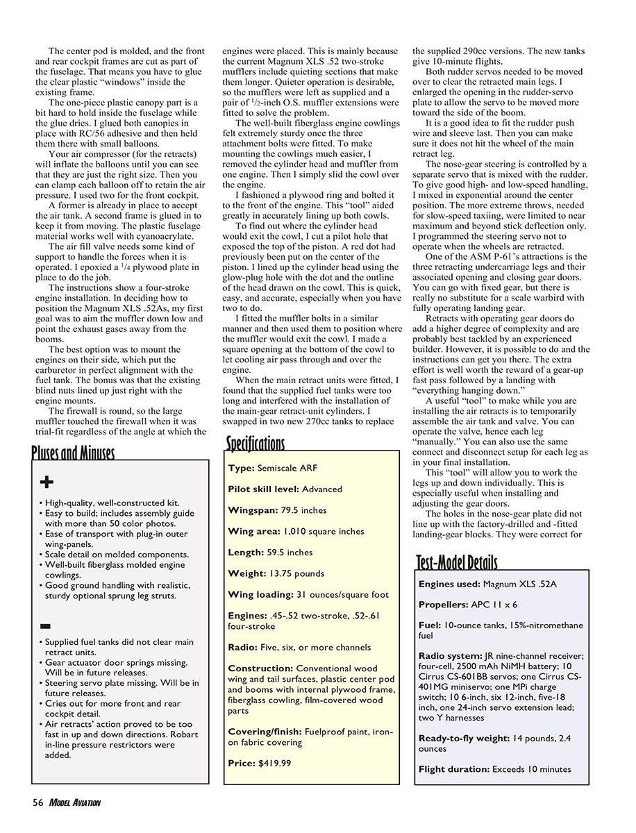
You will need 11 servos to guide this airplane:
- Two for the ailerons
- Two for the flaps
- Two for the rudders
- Two for the throttles
- One for nose-gear steering
- One for the elevator
- One for the retract valve
The radio you choose needs only five channels, and you will then use a load of Y leads. For this review I used a JR 10X transmitter and a nine-channel JR PCM receiver because the JR transmitter has terrific mixing features that allow many options and fine-tuning of the engines and flight/steering controls.
You can build either a glow- or an electric-powered version of the Black Widow. Glow power can be two- or four-stroke engines. The review model was built for two Magnum XLS .52A two-strokes.
You will need basic tools such as:
- A modeling knife
- Screwdrivers and hex wrenches
- Sandpaper and a sanding block
- A couple of airplane stands
- Paper towels
It is necessary to study the instructions before you build the ASM P-61. This is not just the usual rhetoric about building a model; you need to do more than familiarize yourself with all the parts. It is essential to plan how you are going to transport the finished item and how you intend to set up and program your radio. There is a great deal for you to decide.
For instance, you could use three or four Y leads to connect the two throttles, rudders, and flaps, not forgetting the third "rudder" servo that is connected to the front steering leg only. You could use four Y leads and only three channels, but this will limit you to making mechanical adjustments only. Then you would need four 12-inch servo-extension leads to go with the Y leads in the center panel.
If you decide to use two channels for the two throttle servos, two channels for the two rudders, and a third channel for the steering servo, you will be able to adjust all the servos from the transmitter. Instead of Y leads you would use four 18-inch extension leads to reach the servos from the receiver. The four individual leads would be in the center wing panel rather than Y leads.
For this review I used two Y leads: one for the flaps and one for the ailerons. I used separate channels for the two throttles, two rudders, and one steering servo. The steering servo is positioned in the center pod and does not need a servo-extension lead because it plugs directly into the receiver.
The elevator servo is all the way back inside the stabilizer. It needs to have its wiring routed all the way through one boom and then be connected to an extension lead in the center wing panel. This extension lead then connects with a short extension lead coming out of the receiver in the central fuselage pod. You can use more Y leads to cut down the number of wires, but then you lose the programming capability that comes with each servo being connected to its own channel.
It took roughly an hour to plan the extension-and-Y-lead configuration. This is one area where an experienced pilot’s knowledge would probably be needed.
Connecting all the servos required:
- Ten 6-inch leads
- Five 18-inch leads
- Six 12-inch leads
- One 24-inch lead
- Two Y leads
- One 6-inch extension to bring the servo lead out of the end of the stabilizer
Field assembly is much easier if you make sets of labels with something such as a Brother label maker. You could use color coding, but there would be many colors involved. Approximately 40 labels were needed to code every extension and servo lead.
If you plan to keep the P-61 stored and/or transported in a semiassembled state, you will not need to connect and disconnect these leads very often. However, they will still need good and clear identification.
There will also be a pair of airline tubes that go to each retract unit. If you use the Robart in-line quick connect/disconnect units, you can "polarize" the identity of the up-and-down air lines. Use a "male" connector on each up-line and a "female" connector on each down-line so you cannot connect any of the retract units the wrong way.
Assembly
The manual is a series of high-quality photos with notes and basic directions. It is clear that construction is an area in which the builder should have a good amount of RC-model construction knowledge.
It proved helpful to study the pictures and then make assembly lists. It helps to break down the construction into segments such as booms, center pod, wing, etc.
The wing is made from a center panel and two outer panels. The outer panels host the ailerons, flaps, and their servos. The center section is the hub of this airplane and contains all the servo extensions to the outer wing panels, the booms, and the lead to the elevator servo. It also supports the retract control valve, associated servo, and main-gear air lines. In addition to being attached to the main pod, the center wing panel supports the two booms that contain the engines, throttle, rudder servos, and main landing-gear retracts.
The three wing sections use a total of five servos:
- Two operate the ailerons
- Two operate the flaps
- One operates the retract air valve
Before assembly begins you should have decided how you are going to connect and operate all these servos.
I began building by fitting the aileron and flap hinges. The instructions showed Mylar hinges for the ailerons, but the ARF came with pin hinges. Both types work fine, so I fitted the control surfaces with those supplied. I stained the Mylar hinges black with a marker to keep them from showing.
I had to add servo extension leads so the servos would reach the wing joint. The wing panels use aluminum joiner tubes so you can take the wing apart for transport and storage. I applied thin cyanoacrylate to the antirotation dowels. This stops them from swelling in humidity and assures they are glued firmly in place.
The center wing panel is where you mount the air valve and servo for the retractable landing-gear control. The air tank is fitted inside the fuselage pod and requires a line connector to the air-control valve. The wing hatch/gun mount is a removable hatch that covers the valve. This means that if there is any compressed air in the tank, you can operate the gear without having to turn on the radio.
The instructions suggest that you leave the wing tubes bolted in the outer wing panels for easier reassembly and lining up the wing-tube retention bolts. This was good advice.
It's time to construct the fuselage pod. The front and rear cockpit areas use gray prepainted plywood plates as cabin floors. The front plate was made removable to allow maintenance access to the nose gear and steering mechanism.
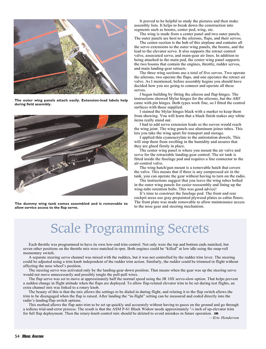
The center pod is molded, and the front and rear cockpit frames are cut as part of the fuselage. That means you have to glue the clear plastic "windows" inside the existing frame. The one-piece plastic canopy part is a bit hard to hold inside the fuselage while the glue dries. I glued both canopies in place with RC/56 adhesive and then held them there with small balloons. Your air compressor (for the retracts) will inflate the balloons until you can see that they are just the right size. Then you can clamp each balloon off to retain the air pressure. I used two for the front cockpit.
A former is already in place to accept the air tank. A second frame is glued in to keep it from moving. The plastic fuselage material works well with cyanoacrylate.
The air fill valve needs some support to handle the forces when it is operated. I epoxied a 1/4-inch plywood plate in place to do the job.
The instructions show a four-stroke engine installation. In deciding how to position the Magnum XLS .52As, my first goal was to aim the muffler down low and point the exhaust gases away from the booms. The best option was to mount the engines on their side, which put the carburetor in perfect alignment with the fuel tank. The bonus was that the existing blind nuts lined up just right with the engine mounts.
The firewall is round, so the large muffler touched the firewall when it was trial-fit regardless of the angle at which the engines were placed. This is mainly because the current Magnum XLS .52 two-stroke mufflers include quieting sections that make them longer. Quieter operation is desirable, so the mufflers were left as supplied and a pair of 1/2-inch O.S. muffler extensions were fitted to solve the problem.
The well-built fiberglass engine cowlings felt extremely sturdy once the three attachment bolts were fitted. To make mounting the cowlings much easier, I removed the cylinder head and muffler from one engine and then simply slid the cowl over the engine. I fashioned a plywood ring and bolted it to the front of the engine. This "tool" aided greatly in accurately lining up both cowls.
To find out where the cylinder head would exit the cowl, I cut a pilot hole that exposed the top of the piston. A red dot had previously been put on the center of the piston. I lined up the cylinder head using the glow-plug hole with the dot and the outline of the head drawn on the cowl. This is quick, easy, and accurate, especially when you have two to do.
I fitted the muffler bolts in a similar manner and then used them to position where the muffler would exit the cowl. I made a square opening at the bottom of the cowl to let cooling air pass through and over the engine.
When the main retract units were fitted, I found that the supplied fuel tanks were too long and interfered with the installation of the main-gear retract-unit cylinders. I swapped in two new 270cc tanks to replace the supplied 290cc versions. The new tanks give 10-minute flights.
Both rudder servos needed to be moved over to clear the retracted main legs. I enlarged the opening in the rudder-servo plate to allow the servo to be moved more toward the side of the boom. It is a good idea to fit the rudder push wire and sleeve last so you can make sure it does not hit the wheel of the main retract leg.
The nose-gear steering is controlled by a separate servo that is mixed with the rudder. To give good high- and low-speed handling, I mixed in exponential around the center position. The more extreme throws needed for slow-speed taxiing were limited to near maximum and beyond stick deflection only. I programmed the steering servo to not operate when the wheels are retracted.
One of the ASM P-61's attractions is the three retracting undercarriage legs and their associated opening and closing gear doors. You can go with fixed gear, but there is really no substitute for a scale warbird with fully operating landing gear. Retracts with operating gear doors do add a higher degree of complexity and are probably best tackled by an experienced builder. However, it is possible to do and the instructions can get you there. The extra effort is well worth the reward of a gear-up takeoff followed by a landing with "everything hanging down."
A useful "tool" to make while you are installing the air retracts is to temporarily assemble the air tank and valve. You can operate the valve and each leg "manually." You can also use the same connect-and-disconnect setup for each leg as in your final installation. This "tool" will allow you to work the legs up and down individually, which is especially useful when installing and adjusting the gear doors.
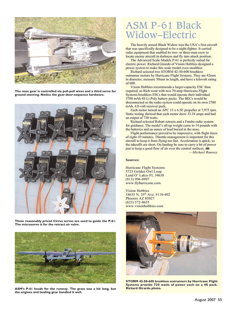
The holes in the nose-gear plate did not line up with the factory-drilled and -fitted landing-gear blocks. They were correct for the fixed-gear plate, so I used it as a guide to drill two new holes to get the nose leg to fit. The nose gear has to be fitted in the forward bolt-holes position to clear the nose wheel during retraction. I sanded the nose-gear area smooth so nothing could snag the pull-pull steering wires.
The compressed-air operation of all the legs proved to be too fast; they made a resounding "whack!" each time the retract units were operated. I cured this by fitting Robart restrictors in the up and down air lines to slow the operation.
The hinges are glued to the inner surface of the retract doors. As insurance I laid small squares of 20-ounce fiberglass cloth over the epoxy, while wet, to hold the hinges in place. When the door hinges are glued to the gear openings, be sure to leave at least a 1/16-inch gap to allow the doors to open fully later. The doors are operated by a hinged plate that is loaded to spring the doors open. They go back when the wheel strikes the plate during retraction and eventually pull them all the way closed.
The instructions give accurate positions for the door-actuating horns. Even so, mainly because of the Z bends, I experienced some difficulty getting the doors to close equally. Fortunately the Internet, and RC Universe in particular, has a construction thread running on this model. Jimmy Bonanno of Urbandale, Iowa, came up with a great solution. He soldered threaded connectors onto the ends of the door-actuator wires and then fitted adjustable clevises. This allowed him to adjust the lengths of the wires perfectly. Now the doors are easy to set. It does not matter how far they open as long as the wheels and legs do not touch them on the way back up.
This is an easy airplane to align. The fins are a part of the fiberglass molded fuselage booms. The wing, booms/fins, and stabilizer alignment has been done for you. The center pod is attached to the wing center panel with two bolts. The two booms attach to the same panel with one bolt each. The stabilizer is inserted between the fins and tightened in place with a bolt at each end. Clip the wing hatch in place and you are finished. There is nothing to adjust or glue.
My airplane was going to be stored and transported fully assembled minus the outer wing panels. This caused one small problem: the bolt that was intended to hold the outer wing panels to the center panel was completely covered by the boom that was already bolted to the wing. The wing tube could have been left in the center panel instead of the outer panel, but it was almost guaranteed to be sticking out at the wrong moment during transport, handling, or storage.
Closer inspection of the center wing revealed that the manufacturer had installed a hardwood block inside the lower wing skin to guide and hold the wing-tube retaining bolt. I reproduced this block and glued it in place inside the top wing surface. Then it was easy to drill a new hole to allow the wing to be bolted in place from the top. Field assembly takes approximately 30 seconds, and best of all the airplane does not need to be flipped over.
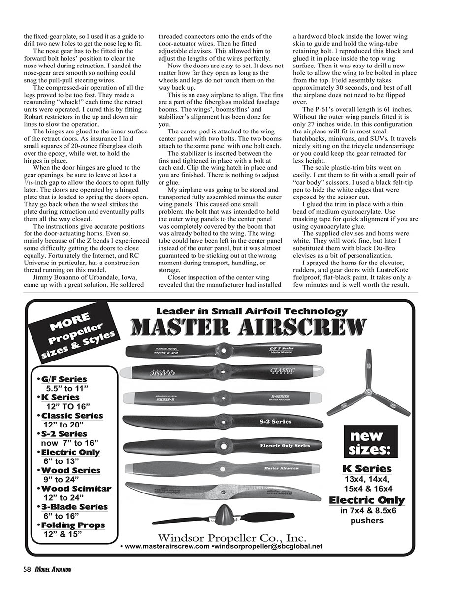
The P-61's overall length is 61 inches. Without the outer wing panels fitted it is only 27 inches wide. In this configuration the airplane will fit in most small hatchbacks, minivans, and SUVs. It travels nicely sitting on the tricycle undercarriage or you could keep the gear retracted for less height.
The scale plastic-trim bits went on easily. I cut them to fit with a small pair of "car body" scissors and used a black felt-tip pen to hide the white edges that were exposed by the scissor cut. I glued the trim in place with a thin bead of medium-viscosity cyanoacrylate. Use masking tape for quick alignment if you are using cyanoacrylate glue.
The supplied clevises and horns were white. They will work fine, but later I substituted them with black Du-Bro clevises as a bit of personalization. I sprayed the horns for the elevator, rudders, and gear doors with Luster-Kote fuelproof flat-black paint. It takes only a few minutes and is well worth the result.
The wing tanks are held in place with screws to allow future access to the flap servos. The four-gun unit on the top of the wing fairing/hatch adds a realistic look. It is well worth taking the time to get all the guns parallel.
It was pleasing to find that the CG came out extremely close to the 3-3/4 inches from the LE specified in the instruction manual. The receiver ended up just behind the steering servo, with the battery under the front canopy deck plate. The final CG was set at the forward position to allow for the slight rearward gravity shift when the landing gear is retracted.
The completed ARF weighs 14 pounds, 2.4 ounces, probably because the retract units are heavier than the fixed-gear options.
Scale Programming Secrets
Each throttle was programmed to have its own low-end trim control. Not only were the top and bottom ends matched, but seven other positions on the throttle mix were matched in rpm. Both engines could be "killed" at low idle using the snap-roll momentary switch.
A separate steering servo channel was mixed with the rudders, but it was not controlled by the rudder trim lever. The steering could be adjusted using a trim knob independent of the rudder-trim action. Similarly, the rudder could be trimmed in flight without affecting the nose wheel's position.
The steering servo was activated only by the landing-gear-down position. That means when the gear was up the steering servo would not move unnecessarily and possibly tangle the pull-pull wires.
The flap servo was set to move at approximately half the normal speed using the JR 10X servo-slow option. That helps prevent a sudden change in flight attitude when the flaps are deployed. To allow flap-related elevator trim to be set during test flights, an extra channel mix was linked to a rotary knob.
The beauty of this is that the mix allows the settings to be dialed in during flight, and relating it to the flap switch allows the trim to be disengaged when the flap is raised. After landing the "in-flight" setting can be measured and coded directly into the radio's landing/flap switch settings.
This method allows the flap auto trim to be set up quickly and accurately without having to guess on the ground and go through a tedious trial-and-error process. The result is that the ASM P-61 Black Widow needs approximately 1/4 inch of up-elevator trim for full flap deployment. Then the rotary-knob-control mix should be deleted to avoid mistakes in future operation.
—Eric Henderson
ASM P-61 Black Widow With Nitro Power
The Magnum XLS .52A is a .52 cu. in. (8.47 cc) two-stroke aircraft engine with a twin-needle carburetor. It features an ABC (aluminum-brass-chrome) piston and sleeve, a standard or rear-needle-valve position option, a high-flow quiet muffler, a dual-ball-bearing-supported crankshaft, and a dual-bushing-supported connecting rod. It weighs 17.4 ounces with the muffler attached.
The .52A has a practical rpm range of 2,200–8,100. The recommended break-in propeller is an APC 10 x 6.
The engine instructions recommended a break-in fuel with 10% nitromethane and 20% castor-oil content. That may be a misprint. A gallon of fuel with some castor content will normally have 20% oil content. Within that 20% oil there is a ratio of synthetic-to-castor oil that should be at least 80:20. The 10% Morgan (pink) fuel that was used had a 70:30 ratio of synthetic-to-castor oil. It was used for initial break-in, and then the same brand with 15% nitro was used for flying.
As with any engine, the XLS .52A should be thoroughly broken in. When running two engines together, it is essential to obtain reliable idles, sustainable high-end rpm, and consistent/smooth throttle responses.
The instructions for how to set the engines are clear and easy to follow. Once the engine can run without overheating, it is a good idea to run it at full throttle for a whole tank before you try to adjust the idle and transition.
Both .52As started easily with an electric starter motor. Not much hand flipping was done, especially when using a three-blade propeller, because there is not much room between the engines in the center pod. An electric starter is a much safer option.
The engines were adjusted one at a time. Both needed their low ends leaned out approximately one-quarter turn to get a good idle. Both idled extremely well and went through the transition to full throttle "cough free."
I tried several propellers during flight-testing. The break-in APC 10 x 6 also did the job during the early test flights. The final propeller I chose was the APC 11 x 6; it gave the best speed and climb rate.
A pair of rare Zingalo 10 x 8 three-blade propellers was just right for scale-looking flight. However, they did not match the pulling power of the 11 x 6, which, with the .52A set slightly rich, would turn comfortably at 12,400 rpm.
Both throttle arms had been set to the same angle, so each servo-to-arm geometry relationship in the final installation was closely matched. This helped when matching and synchronizing the engines with the computer radio.
The pair of Magnum XLS .52As is a wonderful match for the ASM P-61. They fit the cowl installation well but require a 1/2- to 5/8-inch muffler spacer to clear the firewall if you don’t want to cut at the firewall.
—Eric Henderson
Preflight
The wing loading with fixed gear would be 31.36 ounces per square foot. The wing loading with retractable landing gear is 32.2 ounces per square foot. That proved to be practical for this P-61.
The last thing to do was iron down all the covering. You must do this for black iron-on material, and it is a great idea to subsequently keep it out of direct sunlight.
With the engines broken in and synchronized, the nose-wheel servo alignment needs to be tested and set under taxi conditions. The last thing you want is a nose wheel fighting the action of the twin rudders.
The Black Widow taxis with good authority. Mixing in a rotary-knob channel to make steering trim adjustments separate from the rudder trim lever proved to be a satisfying asset. A few short taxi runs were all it took to get the front wheel pointing straight. These runs can also help make sure the engines keep running under "moving" conditions.
Time to Fly
With clean sunglasses and an empty sky I taxied the Black Widow to the center of the runway and aimed it into the wind. The seven-minute countdown timer on the radio was activated.
The engines were slowly opened up and began to roar happily in harmony. As the throttle reached the half-stick position, the airplane twitched slightly on some rough grass and made as if to turn but immediately proceeded to advance quickly in a straight line.
With the P-61 traveling fast on all three wheels I added full power and gently fed in roughly one-quarter up-elevator, and then the nose came up swiftly approximately 10°. The main wheels left the ground and the P-61 was airborne.
At first the climb was getting steeper—too steep for comfort. There was too much up-trim in the elevator. (Later it was determined that there had been too much up-elevator mix for the gear-down condition—a bad guess on my part.) Down-trim was feverishly pegged in and in place before the P-61 entered the first turn. I also input a small amount of left aileron trim (which I later removed after the outer wing-panel flaps and ailerons were better aligned with the center wing panel). I left the landing gear down for a few passes.
The first rule of flying twin-engine models is to gain height as quickly as possible after takeoff. The Magnums were running beautifully and would almost pull the P-61 vertical. Once trimmed, it was time to look at how the airplane was actually flying.
The trim-setting adjustments were the only things needed to achieve a good, steady flight. The controls could be released and the P-61 would fly hands-off if put in straight and level flight. The fuselage stayed pleasantly level when entering a turn.
Later, 1/4 inch of rudder throw either way was coupled to the ailerons to automatically help the turn entry at low speeds. Once banked over, applying elevator only kept the turn going and there was no climbing or diving in left- or right-hand turns.
Different throttle settings showed stable flight at all speeds. Then it was time to pull up the landing gear. This was done at approximately half throttle. There was a slight nose-up trim change on this flight because the corrective trim mix was wrong. It would have been better to add this radio-programmable feature after the test flight.
The clock was ticking, so a landing was next on the agenda. The gear was lowered and the correct elevator trim was re-engaged. At a safe altitude the flaps were fully deployed and the preset flap auto down-elevator engaged itself.
The ASM P-61 dives a bit when the flaps are down. They are positioned outboard of the main engines, which may be why they have that effect. I brought the flaps back up to level and planned a no-flap landing approach.
I selected half throttle and made a landing circuit. Once the airplane was over the runway threshold, roughly one-third throttle made the P-61 slow down visibly. The wings stayed level, and at approximately a foot above the grass the engines were brought back to a high idle.
The Black Widow "floated" steadily 10 yards or so and settled into a smooth landing. The first flight was good, but it definitely fell into the category of needing an experienced pilot.
It took only a few moments to correct the elevator mixes. I set the gear up-and-down mix at barely 1/16 inch up-elevator trim when the landing gear was down. The flap auto elevator-trim dial mix was reversed so flap-related up-elevator trim could be dialed while in flight.
The takeoff was picture-perfect, and the gear was retracted halfway around the field. Long, big-scale rolls with positive "G," often called barrel rolls, were performed with ease. Axial rolls were pleasant to do to the left or the right.
The instructions guide you to put in more up than down aileron throw. That definitely made the ailerons roll the airplane better into the turns.
A huge loop could be pulled with Magnum XLS .52As willingly doing their job. The engines sounded great as they came on "song" for the climb and then "purred" contentedly on the back half of the loop.
Low passes at full throttle were impressive. The most interesting pass may well be when you throttle back to roughly one-quarter power, add the flaps, and then lower the landing gear as you do a slow flyby for the cameras.
With full flap engaged you can do a much steeper final approach with no appreciable gain in airspeed. A short skimming of the grass and a small flare of the elevator lets the wheels settle into a smooth rollout. You can see the gear legs compressing their springs as the Black Widow rolls slowly to a stop.
Landings using the flap were predictable and straightforward. Takeoffs did not like having the flaps down. The nose came up much quicker and easier without the flaps.
Once dialed in the ASM P-61 Black Widow was a delight to fly and throw around the sky. There was no need to worry about potential drag from the wing tanks because this airplane will fly fast with them attached. It loops majestically. Cruising-speed turns and rolls show no adverse yaw.
Slow-speed aileron turns liked a bit of top rudder to be added going into the turn. This can be done manually or mixed in at the time. One practical way of switching aileron-to-rudder mix on and off could be to use the throttle position as a switch.
As far as whether or not the instructions mean an experienced builder or flier, most advanced building and set-up skills are required, as the supplier advises. However, it is fair to claim that, once trimmed, the ASM P-61 is as easy to fly as any low-wing sport model. If you can get some help putting one together and setting it up, this twin could do a lot early in your RC flying life.
The Magnum XLS .52As are more than adequate for this airplane. They run well and sound wonderful when synchronized. You can do full-bore passes that feel "locked" all the way. The ASM P-61 Black Widow's pedigree will let you look like a Scale pilot before it even takes off. It is not designed to be a pure Scale Masters competition aircraft, but it does look real in the sky and in the pits.
This P-61 flies as easily as most 60-size sport models, with no nasty habits. It is great to fly just for fun!
—Eric Henderson [email protected]
ASM P-61 Black Widow—Electric
The heavily armed Black Widow was the USA’s first aircraft specifically designed to be a night-fighter. It carried radar equipment that enabled its two- or three-man crew to locate enemy aircraft in darkness and fly into attack position.
The Advanced Scale Models P-61 is perfectly suited for electric power. Richard Girardo of Vision Hobbies designed a power system to make this scale model even stealthier.
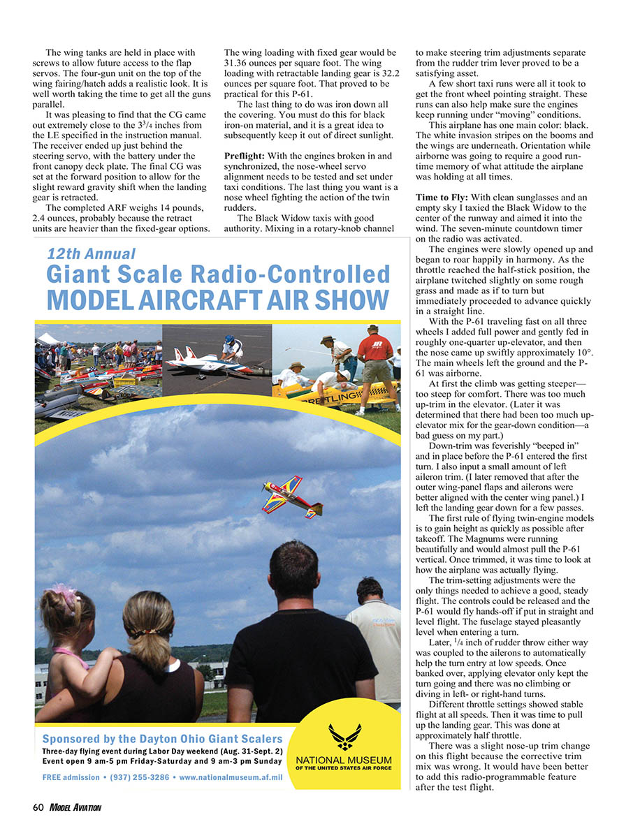
Richard selected two STORM 42-50-600 brushless outrunner motors by Hurricane Flight Systems. They are 42 mm in diameter, measure 50 mm in length, and have a kilovolt rating of 600.
Vision Hobbies recommends a larger-capacity ESC than required, so Rich went with two 70-amp Hurricane Flight Systems brushless ESCs that would operate their individual 3700 mAh 4S Li-Poly battery packs. The BECs would be disconnected so the radio system could operate on its own 2700 mAh, 4.8-volt receiver pack.
Each motor turned an APC 13 x 6.5E propeller at 7,975 rpm. Static testing showed that each motor drew 33.34 amps and produced 730 watts.
Richard selected Robart retracts and a Futaba radio system for guidance. The model’s all-up weight came to 14 pounds with the batteries and an ounce of lead buried in the nose.
Flight performance proved to be impressive, with flight times of eight–10 minutes. Throttle management is important for this aircraft to keep it from flying too fast. Acceleration is quick, so the takeoffs are short. On landing be sure to carry a bit of power just to keep a good flow of air over the control surfaces.
—Michael Ramsey
Pluses and Minuses
- High-quality, well-constructed kit.
- Easy to build; includes assembly guide with more than 50 color photos.
- Ease of transport with plug-in outer wing panels.
- Scale detail on molded components.
- Well-built fiberglass molded engine cowlings.
- Good ground handling with realistic, sturdy optional sprung leg struts.
- Supplied fuel tanks did not clear main retract units.
- Gear actuator door springs missing. Will be in future releases.
- Steering servo plate missing. Will be in future releases.
- Cries out for more front and rear cockpit detail.
- Air retracts' action proved to be too fast in up and down directions; Robart in-line pressure restrictors were added.
Specifications
- Type: Semiscale ARF
- Pilot skill level: Advanced
- Wingspan: 79.5 inches
- Wing area: 1,010 square inches
- Length: 59.5 inches
- Weight: 13.75 pounds
- Wing loading: 31 ounces/square foot
- Engines: .45–.52 two-stroke, .52–.61 four-stroke
- Radio: Five, six, or more channels
- Construction: Conventional wood wing and tail surfaces; plastic center pod and booms with internal plywood frame; fiberglass cowlings; film-covered wood parts
- Covering/finish: Fuelproof paint, iron-on fabric covering
- Price: $419.99
Test-Model Details
- Engines used: Magnum XLS .52A
- Propellers: APC 11 x 6
- Fuel: 10-ounce tanks, 15% nitromethane fuel
- Radio system: JR nine-channel receiver; four-cell, 2500 mAh NiMH battery; 10 Cirrus CS-601BB servos; one Cirrus CS-401MG miniservo; one MPi charge switch; 10 6-inch, six 12-inch, five 18-inch, one 24-inch servo extension leads; two Y harnesses
- Ready-to-fly weight: 14 pounds, 2.4 ounces
- Flight duration: Exceeds 10 minutes
Manufacturer/Distributor
ASM / Global Hobby Distributors 18480 Bandilier Cir. Fountain Valley CA 92708 (800) 854-8471 www.hobbypeople.net
Sources
- Hurricane Flight Systems
5723 Golden Owl Loop Land O’ Lakes FL 34638 (813) 996-6997 www.flyhurricane.com
- Vision Hobbies
18635 N. 35th Ave. #110-402 Phoenix AZ 85027 (623) 572-8655 www.visionhobbies.com
- 11 x 6 APC sport propellers: Landing Products
1222 Harter Woodland CA 95776 (530) 661-0399 www.apcprop.com
- Magnum XLS .52A engines: Global Hobby Distributors
- JR radios and accessories: Horizon Hobby, Inc.
4105 Fieldstone Rd. Champaign IL 61822 (800) 338-4639 www.jrradios.com
- Morgan 15%-nitro fuel
- Retracts and accessories: Robart Manufacturing
Box 1247 Saint Charles IL 60174 (630) 584-7616 www.robart.com
- O.S. muffler extensions: Great Planes Model Distributors
Box 9021 Champaign IL 61826 www.osengines.com
- TopFlite LusterKote paint: Great Planes Model Distributors
Other Resources:
- Model Airplane News: May 2007
Transcribed from original scans by AI. Minor OCR errors may remain.

