
Plane Talk: Carl Goldberg Products Yak 54 ARF
BY ED ALT
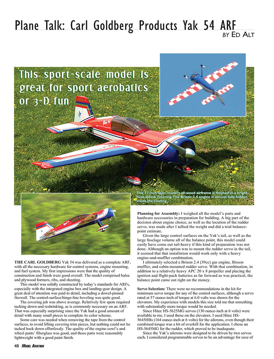
The Carl Goldberg Yak 54 was delivered as a complete ARF with all necessary hardware for control systems, engine mounting, and fuel system. My first impressions were that the quality of construction and finish were good overall. The model comprises balsa and plywood formers, ribs, and sheeting.
This model is solidly constructed by today's ARF standards, especially with the integrated engine box and landing-gear design. A great deal of attention was paid to detail, including a dowel-pinned firewall. The control-surface/hinge-line beveling was quite good.
The covering job was above average. Relatively few spots required tacking down and reshrinking, as is commonly necessary on an ARF. That was especially surprising since the Yak has a good amount of detail with many small pieces to complete its color scheme. Some care is needed when removing tape from the control surfaces to avoid lifting covering trim pieces, but everything can be tacked back down effortlessly.
The quality of the engine cowl and wheel pants' fiberglass was good; the parts were reasonably lightweight with a good paint finish.
Planning for Assembly
I weighed all the model's parts and hardware accessories in preparation for building. A big part of the decision about engine choice, as well as the location of the rudder servo, was made after I tallied the weight and did a trial balance-point estimate.
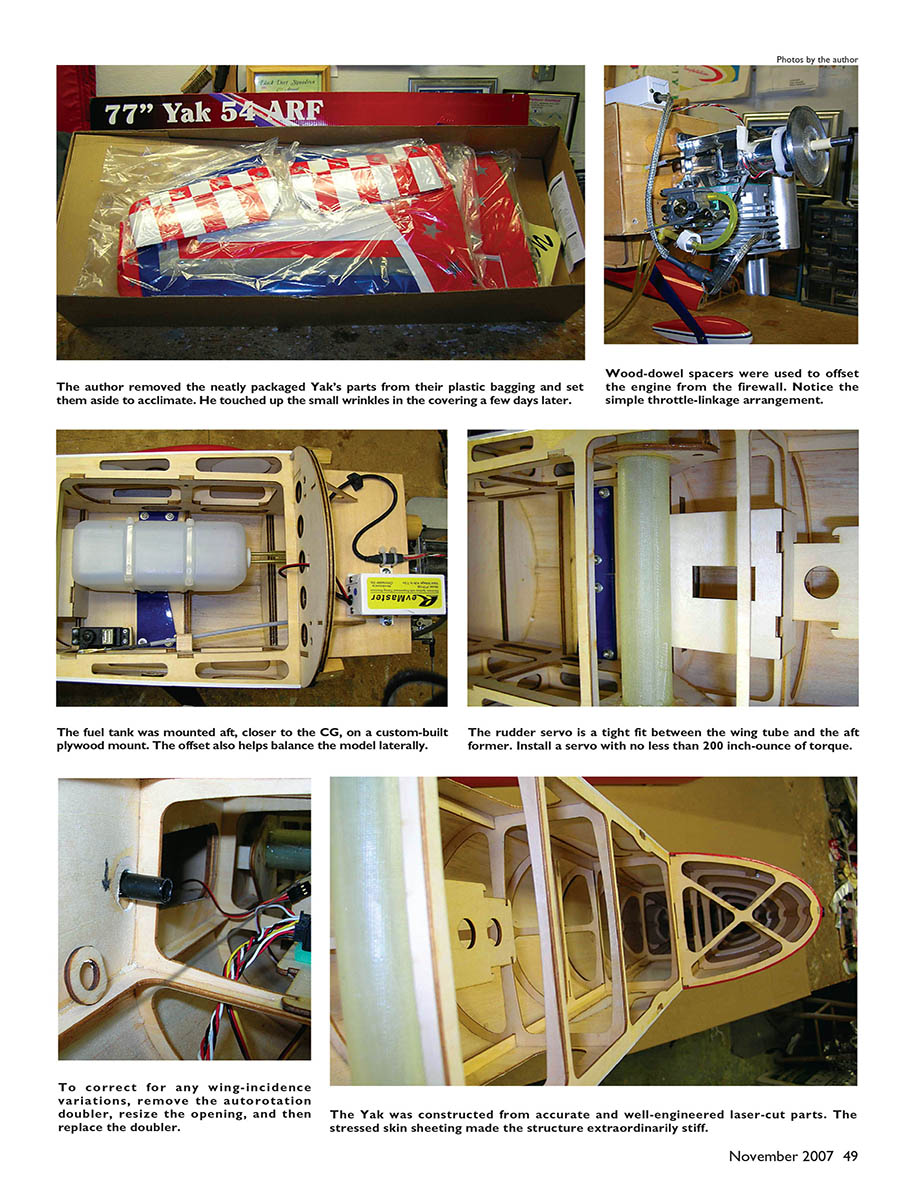
Given the large control surfaces on the Yak's tail and the large fuselage volume aft of the balance point, this model could easily have come out tail-heavy without this preparation. Although mounting the rudder servo in the tail was an option, that installation would likely require a heavy engine-and-muffler combination. I ultimately selected a Brison 2.4 (39cc) gas engine, a Bisson muffler, and a cabin-mounted rudder servo. With that combination, along with a relatively heavy APC 20 × 8 propeller and placing the ignition and flight-pack batteries as far forward as practical, the balance point came out right on the money.
Servo Selection
There were no kit recommendations for minimum servo torque for any control surfaces, although one servo (57 oz-in at 6.0 V) was shown for the elevators. My experience with models this size indicated substantially more torque would be needed.
I used Hitec HS-5625MG servos (130 oz-in at 6 V) on the elevators and Hitec HS-5645HBs (164 oz-in at 6 V) for the ailerons. The HS-5645HBs provided a combined torque that was a bit of overkill for the ailerons, but acceptable. I chose an HS-5645MG for the rudder, which proved to be inadequate for the large rudder/counterbalance area.
Since the Yak's ailerons were designed to be driven by two servos each, I considered programmable servos to be an advantage for ease of installation and setup. Ganging multiple servos on one control surface requires careful attention to control-linkage geometry to ensure that for a fixed amount of servo travel there is a corresponding, equal amount of control-surface deflection. Otherwise servos will fight each other, wasting battery capacity, reducing control effectiveness, and possibly overheating and damaging servos. Matching servo centering and travel endpoints is required for the same reason.
Several means exist to synchronize servos, including devices like the JR MatchBox or using transmitter multi-point mixes. A simple method that works is to use sets of programmable digital servos (such as Hitec’s), which is the approach I chose for simplicity.
Later, to address yaw stability and roll-coupling, I replaced the Hitec rudder servo with a JR DS8611 (296 oz-in at 6 V). That instantly solved yawing and roll-coupling problems and significantly improved knife-edge and snap-roll handling.
Assembly
Overall the instructions were fairly clear and matched what was provided with the kit. Among the minor discrepancies was that control-horn-hole locations were supposed to be partially drilled, but none of the hard points had any locations marked. It was not difficult to find the hard points, but it required careful measurement and drilling to achieve correct control-arm offsets for consistent control-linkage geometry.
There were two construction issues, neither serious: the hole in the fuselage intended to accept the aft autorotation pin for the left wing was misaligned, making it impossible to mate the left wing to the fuselage out of the box. The fix was to pop off the plywood doughnut inside the fuselage that anchors the pin, slightly open the fuselage hole, and reglue the plywood doughnut in the correct location.
The other issue was a slight twist in the left stabilizer; trimming the elevator halves to offset this irregularity corrected it and flying qualities were fine after the small adjustment.
Engine Mounting
The Brison 2.4 fit within the recommended engine requirements but, because it had a rear-mounting flange, it was impossible to use the supplied mounting hardware. I made a set of equal-length hardwood dowels and drilled through the center as mounting spacers to permit proper alignment of the engine. The engine box was already set with the firewall at the correct engine-thrust-offset angle, so the work went quickly.
I selected a Bisson 2.4 inverted muffler, which fit easily inside the large cowl. The Brison engine mounting bolts impinged on the area where the tank was designed to be, so I made a different mounting system and was able to place the tank closer to the balance point. Brison’s Walbro carburetor pumps strongly, so moving it back from the factory location did not pose a fuel-delivery problem.
General Flying Qualities and Trimming
Most flying was done with a 20 × 8 APC propeller, which allowed the Brison 2.4 to operate comfortably up to about 7,700 rpm. With this setup the Yak's vertical penetration was good for moderately difficult aerobatics. It was capable of flying Scale Aerobatics schedules through Sportsman, and with good energy management it could handle Intermediate-level schedules. The model would not perform vertical snaps and very tall complex geometric figures as well as lighter, lower-wing-loading airplanes, though different propeller selections may alter performance somewhat.
The Yak follows design trends for 3-D-capable models: large control-surface areas, hinge-line beveling for extreme throws, and a large aerodynamic counterbalance on the rudder intended to reduce servo demand at extreme deflections. But trade-offs exist: increased control effectiveness at extreme throws can sometimes cause issues around neutral positions.
I noticed a tendency to fishtail at higher cruising speeds and a wander in the roll axis from roll-coupling as the model yawed. Initially I suspected a rear balance-point issue and tried a stronger rudder servo, but even a 168 oz-in HS-5645MG could not fully neutralize the rudder because the airstream grabbed the large counterbalance and caused unwanted deflection. Switching to the JR DS8611 (296 oz-in) solved the yawing and roll-coupling problems and improved knife-edge and snap-roll control.
After resolving the fishtail and roll-coupling issues, I followed standard aerobatic trimming procedures. Small trim changes were needed; most adjustments were corrected with slight clevis turns. I put in two clevis turns of offset to the left elevator to compensate for the left stabilizer twist and achieved good tracking through positive and negative looping figures.
I carried a small amount of right rudder trim to balance up-line tracking without causing unwanted skidding during level flight. Some rudder use is necessary to offset propeller spiral-slipstream effects during vertical maneuvers, especially during the transition from level to vertical, but the amount was normal.
I added an 8% down-elevator mix at throttle idle to prevent down-line shallowing (pulling toward the canopy). This percentage was slightly higher than normal, likely because the Yak was a bit heavy at 16 lb 8 oz, which required more pitch-up force to hold up lines. The Yak also needed 8% rudder-to-aileron mix to counteract a proverse roll during knife edge. Pitch coupling was minimal.
Sport and Precision Aerobatics
Tracking through inside and outside looping figures was good when started at appropriate cruising speed from a horizontal attitude. Sharp-radius figures were not as clean as larger figures because the Yak tended to wallow a bit due to relatively high wing loading if the radius was pulled tight.
The Yak rolls nicely at moderate to high cruising speeds with little rudder work. I did not need to adjust differential; the model rolled straight and true with recommended throws. For finesse rolling maneuvers at low airspeeds and very slow roll rates, rudder and elevator workload is higher but good results are achievable.
The large rudder is extraordinarily effective during Hammerheads, which can be done within a half wingspan with minimal tail wag after yaw-over. Carrying a bit of fast idle over the top was sufficient. With the correct rudder servo, knife-edge flight at various speed ranges was good; the Yak likes a good cruising speed to keep fuselage attitude reasonable during knife edge, point rolls, or slow rolls in sequence flying.
For show-off aerobatics you can combine an extreme fuselage angle and excessive rudder with plenty of throttle for an impressive low-and-slow knife-edge pass. At full power a series of knife-edge-to-knife-edge snaps are fairly easy to catch accurately and continue up to roughly 45° knife-edge climbout.
Upright and inverted flat turns were effective, and the Yak could do tail-over-nose tumbles integrated into those flat turns with a bit of power. Heliogon circles executed well at moderate airspeeds.
Snaps worked well once everything was set up correctly. Positive and negative snaps in various attitudes behaved nicely if entered with decent airspeed and power to pull through. For vertical up-line snaps, keep up-lines short before and after the snap; unloading most of the elevator after the initial pitch break helps maintain a good exit line.
Upright and inverted spins need planning if doing multiple rotations. With its relatively high wing loading the Yak tends to descend fairly quickly after the pitch break and autorotation starts. Spin rotation rate was comfortable and easy to time for recovery. I found it helpful to be partially on the power during spin recovery for a crisper transition back to level flight. Flat spins (e.g., as part of a Blender maneuver) work well with half or more throttle rolled in to reduce descent rate and keep rotation high. It’s important to have power available to aid recovery.
3-D Aerobatics
The Yak handles 3-D rolling maneuvers well, though it has a slightly heavy feel and requires keeping power a bit more than halfway. It won’t float like an ultra-light 3-D trainer but still looks good performing 3-D maneuvers. Transitions from straight-line rollers to circling were manageable as long as speed was maintained.
I was able to take the model from a 3-D Rolling Circle into about three-quarters of a 3-D Rolling Loop; I elected not to continue the loop that day. The Yak did Walls without snapping away but tended to mush through them a bit; controlling the aftermath required prompt application of power.
Parachute approaches worked but did not produce a full “stop and suspend” effect; the model would mush through somewhat and needed power promptly to sustain transitions. Elevators had some wing rock that might stabilize with some crow mix in the ailerons, though I did not try that. Blenders were exciting; from roughly 400 ft altitude the Yak popped up nicely into elevator-roll-to-negative-snap transitions into flat spins.
Hovering and torque rolls required a fair bit of power at this Yak’s weight; the setup was capable but not ideal for learning. You need to get deep quickly at full throttle if a hover abort is necessary at low altitude. I was unable to get more than one consecutive Waterfall; power-to-weight was the limiting factor.
Overall, the Goldberg Yak 54 gives the capability to cross over between a good range of 3-D maneuvers and medium-difficulty precision sequence flying with modest investment.
Specifications
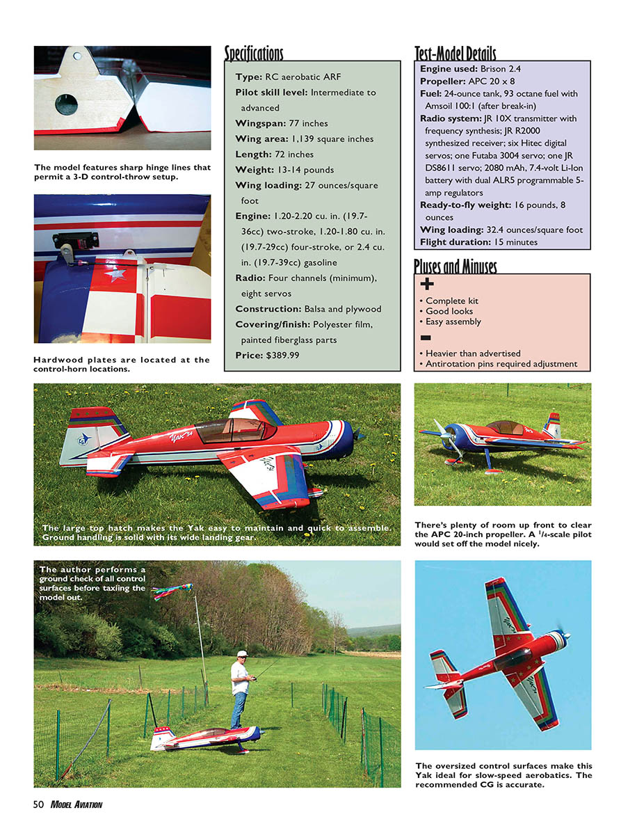
- Type: RC aerobatic ARF
- Pilot skill level: Intermediate to advanced
- Wingspan: 77 inches
- Wing area: 1,139 sq in
- Length: 72 inches
- Weight: 13–14 pounds (recommended); test model 16 lb 8 oz ready-to-fly
- Wing loading: 27 oz/sq ft (catalog) — test-model 32.4 oz/sq ft
- Engine: 1.20–2.20 cu in (19.7–36 cc) two-stroke, 1.20–1.80 cu in (19.7–29 cc) four-stroke, or 2.4 cu in (39 cc) gasoline
- Radio: Four channels (minimum), eight servos
- Construction: Balsa and plywood
- Covering/finish: Polyester film, painted fiberglass parts
- Price: $389.99
Test-Model Details
- Engine used: Brison 2.4
- Propeller: APC 20 × 8
- Fuel: 24-ounce tank; 93 octane fuel with Amsoil 100:1 (after break-in)
- Radio system: JR 10X transmitter with frequency synthesis; JR R2000 synthesized receiver; six Hitec digital servos; one Futaba 3004 servo; one JR DS8611 servo; 2080 mAh, 7.4 V Li‑Ion battery with dual ALR5 programmable 5-amp regulators
- Ready-to-fly weight: 16 lb 8 oz
- Wing loading: 32.4 oz/sq ft
- Flight duration: 15 minutes
Pluses and Minuses
- Complete kit
- Good looks
- Easy assembly
- Heavier than advertised
- Antirotation pins required adjustment
Brison 2.4 Engine
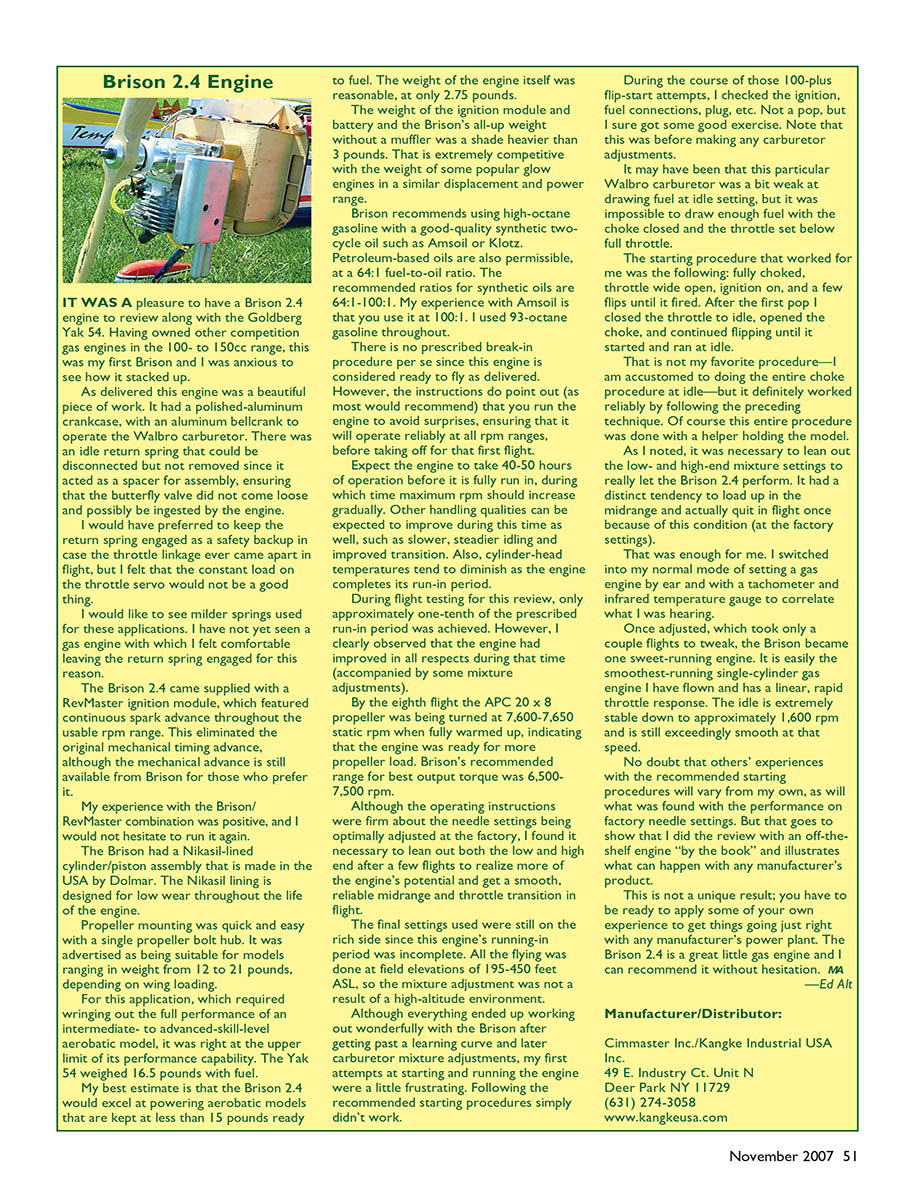
It was a pleasure to have a Brison 2.4 engine to review along with the Goldberg Yak 54. As delivered the engine was a beautifully finished piece with a polished-aluminum crankcase and an aluminum bellcrank to operate the Walbro carburetor. There was an idle-return spring that could be disconnected but not removed because it acted as an assembly spacer to ensure the butterfly valve did not come loose. I would have preferred to keep the return spring engaged as a safety backup in case the throttle linkage ever came apart in flight, but I felt the constant load on the throttle servo would not be desirable. I’d like to see milder springs used for these applications.
The Brison 2.4 came supplied with a RevMaster ignition module featuring continuous spark advance throughout the usable rpm range, eliminating the original mechanical timing advance (though the mechanical advance is still available from Brison). My experience with the Brison/RevMaster combination was positive and I would not hesitate to run it again.
The Brison has a Nikasil-lined cylinder/piston assembly made in the USA by Dolmar. The Nikasil lining is designed for low wear throughout the engine life. Propeller mounting is quick and easy with a single propeller hub nut. Brison advertises this engine as suitable for models ranging from about 12 to 21 pounds, depending on wing loading.
For this application—an intermediate- to advanced-skill-level aerobatic model—the Brison was at the upper limit of its performance capability. The Yak 54 weighed 16.5 lb with fuel. I estimate the Brison 2.4 excels at powering aerobatic models kept under 15 lb ready-to-fly. The engine weight was reasonable at about 2.75 lb; the ignition module and battery pushed the all-up weight without a muffler to just over 3 lb, which is competitive with popular glow engines of similar displacement.
Brison recommends high-octane gasoline with a good-quality synthetic two-cycle oil such as Amsoil or Klotz. Petroleum-based oils are permissible at 64:1 fuel-to-oil ratio. Recommended ratios for synthetic oils are 64:1–100:1; my experience with Amsoil is to use 100:1. I used 93-octane gasoline throughout.
There is no prescribed break-in procedure as the engine is considered ready to fly as delivered, but the instructions recommend running the engine to ensure reliability across rpm ranges before first flight. Expect 40–50 hours for full run-in, during which maximum rpm should gradually increase and handling qualities (idle stability, transition) improve as valve seating improves. Cylinder-head temperatures also tend to diminish over run-in.
During flight testing for this review I achieved roughly one-tenth of the prescribed run-in period but observed improvements during that time after minor carburetor adjustments. By the eighth flight the APC 20 × 8 prop was turning about 7,600–7,650 static rpm when fully warmed up, indicating the engine was ready for more propeller load. Brison’s recommended range for best output torque is 6,500–7,500 rpm.
Although the operating instructions stated needle settings were optimal at the factory, I found it necessary to lean both low and high ends after a few flights to realize more of the engine’s potential and smooth midrange/transition in flight. Final settings used were still on the rich side since run-in was incomplete. All flying was done at field elevations of 195–450 ft ASL, so mixture adjustments were not altitude-related.
My first attempts at starting and running the engine were somewhat frustrating; following the recommended starting procedures did not work reliably. After 100-plus flip-start attempts I checked ignition, fuel connections, and spark plug—no spark on several attempts—before making carburetor adjustments. It may have been that the particular Walbro carburetor was weak at drawing fuel at idle. The starting procedure that worked for me was: fully choked, throttle wide open, ignition on, a few flips until it popped, then close throttle to idle, open choke, and continue flipping until it started and ran at idle. That procedure worked reliably when done with a helper.
As noted, it was necessary to lean low- and high-end mixtures to get the Brison 2.4 to perform. I experienced a midrange loading tendency and once quit in flight at factory settings. After adjusting by ear with a tachometer and infrared temperature gauge, and a couple of tweaking flights, the Brison became a smooth-running engine—easily the smoothest single-cylinder gas engine I’ve flown with linear, rapid throttle response. Idle is extremely stable down to roughly 1,600 rpm.
Others’ experiences with starting and factory needle settings may vary. You should be prepared to apply your own experience to get any manufacturer’s powerplant running optimally. The Brison 2.4 is a great little gas engine and I can recommend it without hesitation.
—Ed Alt
Manufacturer/Distributor (Brison/RevMaster): Cimmaster Inc./Kangke Industrial USA Inc. 49 E. Industry Ct., Unit N Deer Park, NY 11729 (631) 274-3058 www.kangkeusa.com
Manufacturer/Distributor (Yak 54):
Carl Goldberg Models Box 88 Oakwood, GA 30566 (678) 450-0085 www.carlgoldbergproducts.com
Products Used In Review
- Radio: JR — (217) 352-1913 — www.horizonhobby.com
- Servos: Hitec — (858) 748-6948 — www.hitecrcd.com
Other Printed Review Sources
- None
Transcribed from original scans by AI. Minor OCR errors may remain.

