
Plane Talk: Dymond Modelsport Bearcat ARF
Michael Ramsey
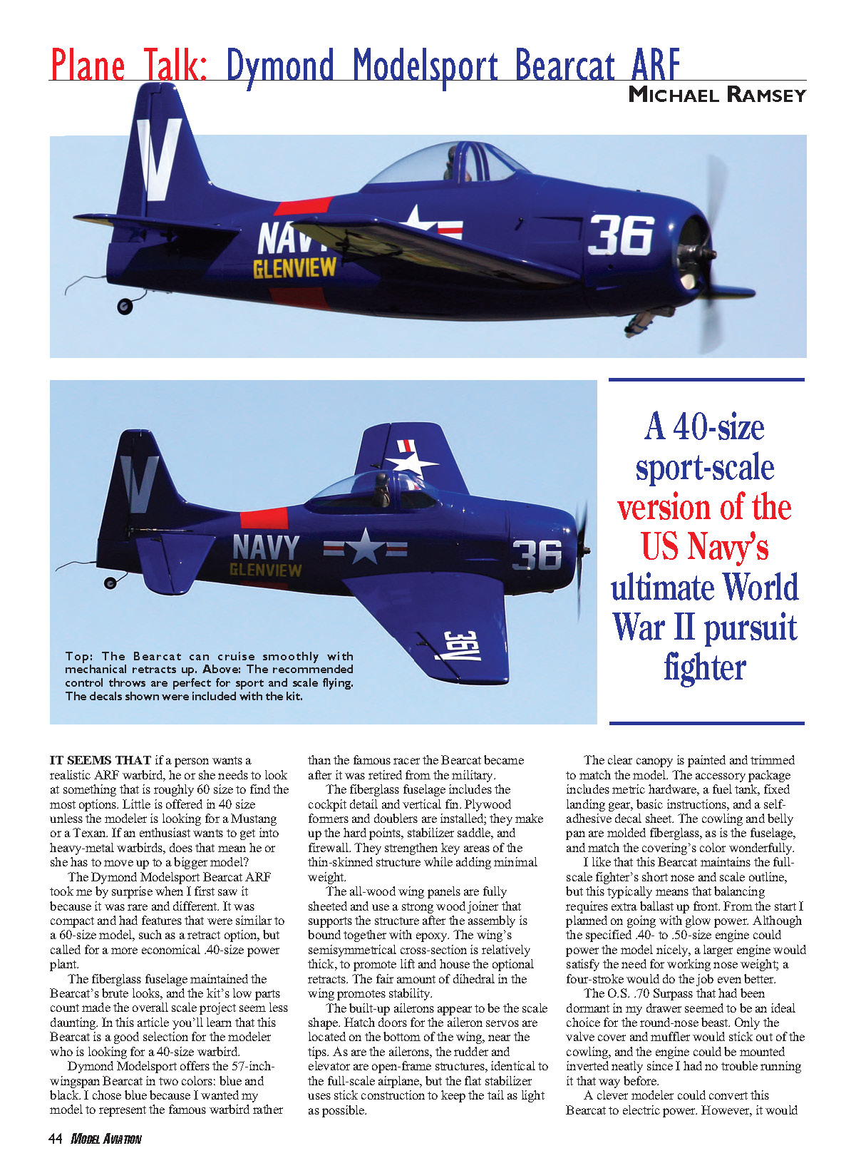
It seems that if a person wants a realistic ARF warbird, he or she needs to look at something that is roughly 60-size to find the most options. Little is offered in 40 size unless the modeler is looking for a Mustang or a Texan. If an enthusiast wants to get into heavy-metal warbirds, does that mean he or she has to move up to a bigger model?
The Dymond Modelsport Bearcat ARF took me by surprise when I first saw it because it was rare and different. It was compact and had features that were similar to a 60-size model, such as a retract option, but called for a more economical .40-size power plant.
The fiberglass fuselage maintains the Bearcat’s brute looks, and the kit’s low parts count makes the overall scale project seem less daunting. The 57-inch-wingspan Bearcat is offered in two colors: blue and black. I chose blue because I wanted my model to represent the famous warbird rather than the famous racer the Bearcat became after it was retired from the military.
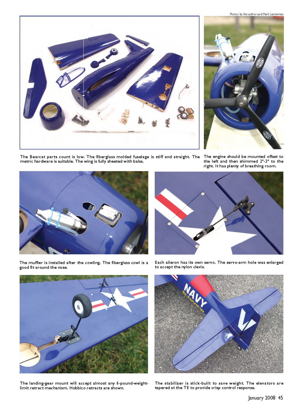
The fiberglass fuselage includes cockpit detail and a vertical fin. Plywood formers and doublers are installed to make up the hard points, stabilizer saddle, and firewall. They strengthen key areas of the thin-skinned structure while adding minimal weight.
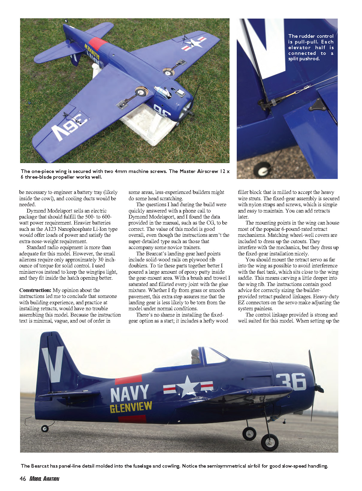
The all-wood wing panels are fully sheeted and use a strong wood joiner that supports the structure after the assembly is bound together with epoxy. The wing’s semisymmetrical cross-section is relatively thick to promote lift and accommodate the optional retracts. The fair amount of dihedral in the wing promotes stability.
The built-up ailerons appear to be scale shape. Hatch doors for the aileron servos are located on the bottom of the wing near the tips. As are the ailerons, the rudder and elevator are open-frame structures, identical to the full-scale airplane, but the flat stabilizer uses stick construction to keep the tail as light as possible.
The clear canopy is painted and trimmed to match the model. The accessory package includes metric hardware, a fuel tank, fixed landing gear, basic instructions, and a self-adhesive decal sheet. The cowling and belly pan are molded fiberglass, as is the fuselage, and match the covering’s color wonderfully.
I like that this Bearcat maintains the full-scale fighter’s short nose and scale outline, but this typically means that balancing requires extra ballast up front. From the start I planned on going with glow power. Although the specified .40- to .50-size engine could power the model nicely, a larger engine would satisfy the need for working nose weight; a four-stroke would do the job even better.
The O.S. .70 Surpass that had been dormant in my drawer seemed to be an ideal choice for the round-nose beast. Only the valve cover and muffler would stick out of the cowling, and the engine could be mounted inverted neatly since I had no trouble running it that way before.
A clever modeler could convert this Bearcat to electric power. However, it would be necessary to engineer a battery tray (likely inside the cowl), and cooling ducts would be needed. Dymond Modelsport sells an electric package that should fulfill the 500- to 600-watt power requirement. Heavier batteries such as the A123 Nanophosphate Li-Ion type would offer loads of power and satisfy the extra-nose-weight requirement.
Standard radio equipment is more than adequate for this model. The small ailerons require only approximately 30 in.-oz. of torque for solid control. I used mini servos to keep the wingtips light, and they fit inside the hatch opening better.
Construction
My opinion about the instructions led me to conclude that someone with building experience and practice at installing retracts would have no trouble assembling this model. Because the instruction text is minimal, vague, and out of order in some areas, less-experienced builders might do some head scratching. The questions I had during the build were quickly answered with a phone call to Dymond Modelsport, and I found the data provided in the manual, such as the CG, to be correct. The value of this model is good overall, even though the instructions aren't the super-detailed type that accompany some novice trainers.
The Bearcat's landing-gear hard points include solid-wood rails on plywood rib doublers. To tie these parts together better I poured a large amount of epoxy putty inside the gear-mount area and saturated and filleted every joint with the glue mixture. Whether I fly from grass or smooth pavement, this extra step assures me that the landing gear is less likely to be torn from the model under normal conditions.
There's no shame in installing the fixed-gear option as a start; it includes a hefty wood filler block milled to accept the heavy wire struts. The fixed-gear assembly is secured with nylon straps and screws, which is simple and easy to maintain. You can add retracts later.
The mounting points in the wing can house most popular 6-pound-rated retract mechanisms. Matching wheel-well covers are included to dress up the cutouts. They interfere with the mechanics, but they dress up the fixed-gear installation nicely.
Mount the retract servo as far into the wing as possible to avoid interference with the fuel tank, which sits close to the wing saddle. This means carving a little deeper into the wing rib. The instructions contain good advice for correctly sizing the builder-provided retract pushrod linkages. Heavy-duty EZ connectors on the servo make adjusting the system painless.
The control linkage provided is strong and well suited for this model. When setting up the aileron control, consider adjusting the linkage to include mechanical differential: more up than down movement. This setup will promote axial rolls and lessen the possibility of tip-stalling at low speeds when high deflections of aileron input induce a roll-reversal effect. Computer-radio users can program in this option and experiment to find out how much this setup helps.
All the slots are precut for the cyanoacrylate-type hinges. The beveled control surfaces have a nice, sharp point so the hinge gap can be made as minimal as possible.
There's a slight mix-up in the directions: they instruct the builder to install the rudder before the tail-wheel assembly. Install the tail wheel, then bend the wire at the proper location to make a tiller arm. Transfer the tiller-arm location to the rudder and trim the area as necessary for a tight fit. Permanently glue the rudder in place with a generous amount of epoxy on the tiller arm so it can take the steering loads.
The slot in the tail for the horizontal stabilizer is oversized so that final alignment to the wing can be completed easily. The instructions for how to align everything were great. Be sure to shim the stabilizer evenly with plywood so you don't change its incidence. Sand the saddle to promote a good bond of the epoxy/microballoon mix and balsa stabilizer. You can hide the glue seam later with a few light coats of Top Flite LustreKote Sapphire Blue sprayed into a dish and then applied with a fine-tip brush.
The rudder is controlled using a lightweight pull-pull system. The only challenge to the builder here is where to locate the exit holes in the fuselage. A yardstick is helpful in projecting where the holes should be located on the fuselage side. Mark on the outside where the servo arms are located, and draw a line from that point to the control horns. It's important that the pushrod exits straight to prevent binding. The elevator pushrod and rudder-cable exit holes should end up over the middle of the stabilizer.
Elevator control is managed with the factory-assembled split pushrod. To prevent flutter and improve the accuracy of the independent elevator halves' movement, add a balsa pushrod support at the former between the stabilizer and the wing. I used 1/4 x 1/2 stick balsa with a 3/8-inch hole drilled on center to support the wood pushrod. Do not skip this modification if you choose to overpower your Bearcat, as I did.
Locate the engine by using the hole in the center of the firewall as a guide. Offset the engine to the left and shim it so right thrust can be added. For a strong power plant such as the O.S. .70, I found 3° of right thrust to be helpful. If a .40 engine is used, approximately 2° of right offset will work fine.
Mount the engine on the nylon rails as far forward as possible to effectively distribute the weight. The cowl should be mounted so that there's a gap at the back of the right and left sides. These bulges will promote air flow through the openings and keep the engine cool.
Mount the battery and receiver as far forward in the model as possible. I added a pilot to the cockpit before securing the canopy with RC/56 adhesive. Sandbags were helpful to weight the canopy down around the lip molded into the fuselage.
The belly pan was fitted to the wing as the canopy was, using sandbags to hold the parts together while the glue dried. I added strips of balsa to the inside of the belly pan to increase the glue contact area. I covered the gap between the two parts on the wing with Sapphire Blue MonoKote.
With the Bearcat completely assembled, I placed it inverted on a Great Planes balancing stand. I had to add 5.8 ounces of ballast to the model's nose to achieve the recommended CG. I mixed lead shot with a small amount of epoxy and distributed it evenly around the front inside lip of the cowling. Once the cowl was ready I fitted it back onto the model for the final CG check. Bits of the lead shot could be drilled out if fine-tuning was required.
The airplane's covering doesn't like extreme heat; it darkens the pigment. The decals added the finishing touches to the model. Another final touch would have been to seal the gear recesses with matching fuelproof paint. The control surfaces were set to have the recommended control movement as low rates and maximum deflection at high rates.
The Master Airscrew 12 x 6 three-blade propeller absorbed the engine’s extra horsepower and provided a unique sound. There’s enough ground clearance to support a 13-inch propeller.
Although this Bearcat’s gear length is shorter than scale, its low-rider form made ground handling much easier. I did all testing from a paved runway. The small wheels included with the model were well suited to this environment, but those who fly from grass might nose-over more easily. Consider larger wheels and opening the recesses in the wing.
Because of the higher-than-specified wing loading on my test model, the first takeoff and subsequent maneuvers were done in a scale and graceful fashion. I didn’t want to do anything abrupt that would cause the model to snap.
Flight Impressions
The Bearcat left the ground just after the smooth throttle application passed the halfway point. The .70’s power was overkill, but it was very cool. The low rates provided the smooth control maneuverability I was hoping for. The Bearcat reached a high testing altitude before the first circuit around the field could be completed. Confidence in this airplane was built quickly, and on the second pass the retractable gear was brought up—although the model was too high to appreciate the sequence.
The Bearcat cruised smartly with the throttle set at just less than half. In cruise only small trim adjustments were required, mostly to the elevator. The 3° of right thrust compensated for the large engine’s torque; pulls to vertical and loops could be flown straight with little or no rudder correction. I had no complaints about the aileron control, and rolling was axial and smooth, as predicted. Crisp point rolls were also possible.
Slow-speed testing had me grinning because the heavy Bearcat showed no bad habits. Stalls were soft and always broke to the left, either up- or downwind. Testing the model at high rates showed that rolls could be made as fast as with a 3-D sport model, but the pitch stability was harder to manage.
I could see the higher control deflections being helpful for point rolls, but the higher elevator rate is probably best used only while taxiing. I planned approximately 30% exponential to be programmed into the high rates later. I used full throttle only for climbing. During initial high-speed testing I confirmed why the elevator pushrod support was needed: fast, heavy models create enough load on the tail to create flutter. Later testing with the pushrod support installed showed that the Bearcat could dive and run flat out with no problems.
Earlier slow-speed testing also confirmed that aileron control faded near the stall break, so landings were best performed well above stall speed. This airplane’s solid feel was a comfort during the landing sequence. Once lined up on the runway, it was easy to settle down to the centerline. The low-rate control input provided smooth pitch corrections that allowed the model to maintain steady airspeed until the flare. I wouldn’t describe this short-coupled aircraft as touchy at all.
The Bearcat slows quickly once the throttle is reduced, so high-throttle landing approaches won’t stretch into long glides. This model is easy to fly and land exactly where you want it. It is possible to three-point the landing since the wingtips stay level well after the stall has occurred.
During later flights, tighter turns proved comfortable to perform; again, no high-wing-loading issues surfaced. Inverted flight requires just a touch of down, so the balance point is precisely where I like it for this type of model. Snaps can be flown, but they don’t look like something a Bearcat should do.
I’ve been flying this model for almost a full season and the Hobbico retracts are wearing out. No structural issues have surfaced, but some cracks in the paint are appearing on the cowl. Since I fly the model at half throttle most of the time, I don’t see any reason why a .40-class engine couldn’t work well in this Bearcat. More ballast would be needed in the nose area, which would put more stress on the cowl mounting points. I like the extra power the .70 provides, and who doesn’t like a model that accelerates quickly?
The Dymond Modelsport Bearcat has been a fun project. It turns heads at the field, and because of its small size I can fit other models in the car with it for a well-rounded day of flying. If you want one of these airplanes, keep in mind that the quantity might be limited. If Dymond Modelsport came out with another warbird like the Bearcat, I’m sure it would also be worthy of serious consideration.
MA Michael Ramsey [email protected]
Pluses and Minuses
- Compact size to suit smaller glow engines
- Fiberglass fuselage with handsome scale detail
- Ready for retracts
- Fast, nimble performance
- Generic instructions are not for beginners
- Landing-gear mounts need reinforcement
- Excessive ballast is required
- Elevator pushrod support is required
Test-Model Details
- Engine used: O.S. FS-70 Surpass
- Propeller: Master Airscrew 12 x 6 three-blade
- Fuel: 12.5-ounce tank, Magnum #1 fuel
- Radio system: Hitec Optic 6 transmitter; Hitec receiver; three Hitec HS-325 servos; two Hitec HS-81 servos; one Futaba 136G retract servo
- Battery: 600 mAh, 4.8-volt battery
- Extensions/harness: three 12-inch extensions; one Y harness; one 9-inch extension
- Ready-to-fly weight: 6 pounds 14 ounces
- Ready-to-fly wing loading: 31.7 ounces/square foot
- Flight duration: 10–15 minutes
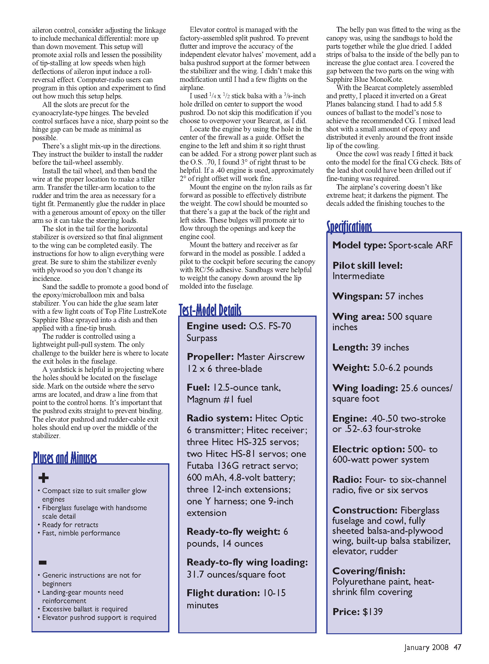
Specifications
- Model type: Sport-scale ARF
- Pilot skill level: Intermediate
- Wingspan: 57 inches
- Wing area: 500 square inches
- Length: 39 inches
- Weight: 5.0–6.2 pounds
- Wing loading: 25.6 ounces/square foot (recommended spec)
- Engine: .40–.50 two-stroke or .52–.63 four-stroke
- Electric option: 500–600 watt power system
- Radio: Four- to six-channel radio, five or six servos
- Construction: Fiberglass fuselage and cowl, fully sheeted balsa-and-plywood wing, built-up balsa stabilizer, elevator, rudder
- Covering/finish: Polyurethane paint, heat-shrink film covering
- Price: $139
Manufacturer/Distributor
Dymond Modelsport Ltd. 3904 Convoy St. #110 San Diego, CA 92111 (858) 495-0092 www.rc-dymond.com
Products Used in Review
- FS-70 II Surpass: O.S. Engines — (217) 398-8970 — www.osengines.com
- Radio system: Hitec — (858) 748-6948 — www.hitecrcd.com
- Retract servo: Futaba — (217) 398-8970 — www.futaba-rc.com
- Propeller: Master Airscrew — (916) 631-8385 — www.masterairscrew.com
Other Review Sources
- None
Transcribed from original scans by AI. Minor OCR errors may remain.

