

Plane Talk: E-flite Deuces Wild ARF
Joe Hass
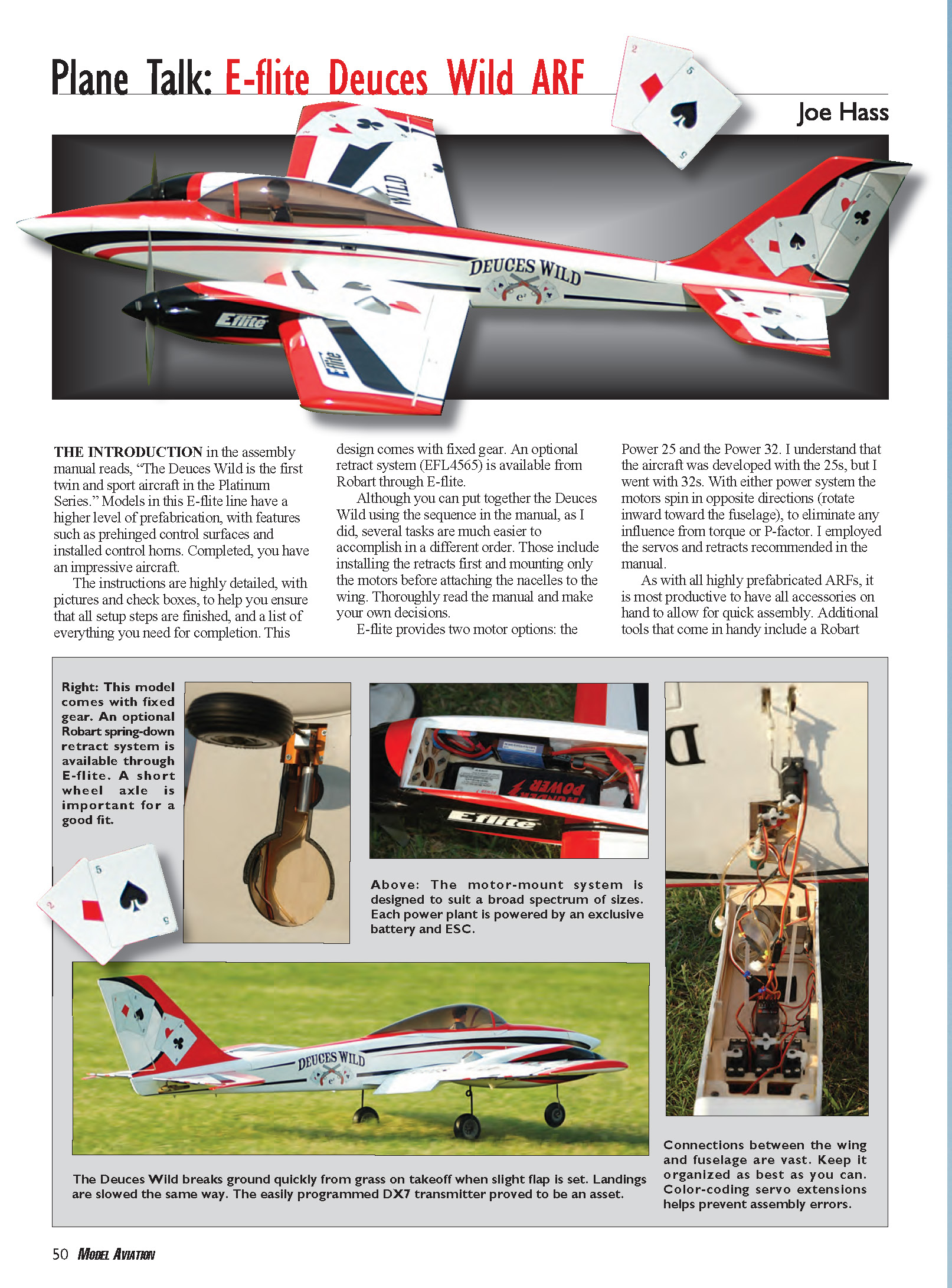
The introduction in the assembly manual reads, "The Deuces Wild is the first twin and sport aircraft in the Platinum Series." Models in this E-flite line have a higher level of prefabrication, with features such as prehinged control surfaces and installed control horns. Completed, you have an impressive aircraft.
The instructions are highly detailed, with pictures and check boxes to help ensure all setup steps are finished, and a list of everything you need for completion. This design comes with fixed gear; an optional retract system (EFL4565) is available from Robart through E-flite.
Although you can assemble the Deuces Wild using the sequence in the manual, several tasks are easier if done in a different order. I recommend installing the retracts first and mounting only the motors before attaching the nacelles to the wing. Thoroughly read the manual and make your own decisions.
E-flite provides two motor options: the Power 25 and the Power 32. The aircraft was developed with the Power 25s, but I used Power 32s. With either power system the motors spin in opposite directions (rotate inward toward the fuselage) to eliminate torque or P-factor influence. I used the servos and retracts recommended in the manual.
As with all highly prefabricated ARFs, have all accessories on hand for quick assembly. Additional tools that come in handy include a Robart foam stand, professional-grade hex drivers, and an inexpensive bar stool (more about that later). Below I review the assembly steps in the order I would have preferred, explain challenges I faced, and offer suggestions to resolve them.
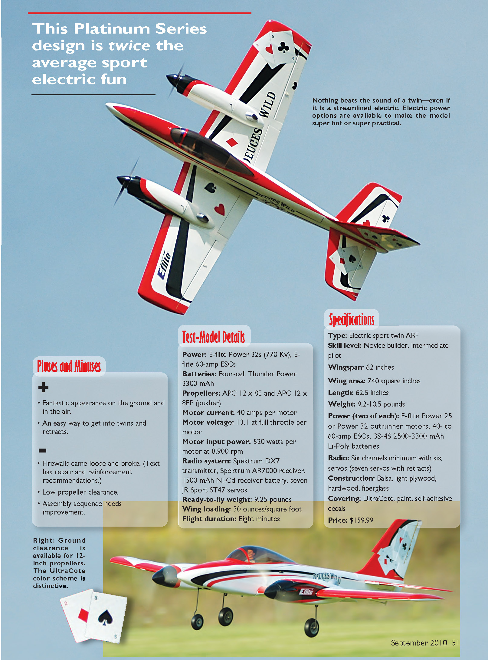
Nothing beats the sound of a twin—even a streamlined electric. Electric power options are available to make the model super hot or super practical.
Pluses and Minuses
- Fantastic appearance on the ground and in the air.
- An easy way to get into twins and retracts.
- Firewalls came loose and broke (repair and reinforcement recommendations included).
- Low propeller clearance.
- Assembly sequence needs improvement.
Test-Model Details
- Power: E-flite Power 32s (770 Kv), E-flite 60-amp ESCs
- Batteries: Four-cell Thunder Power 3300 mAh
- Propellers: APC 12 x 8E and APC 12 x 8EP (pusher)
- Motor current: 40 amps per motor
- Motor voltage: 13.1 V at full throttle per motor
- Motor input power: 520 watts per motor at 8,900 rpm
- Radio system: Spektrum DX7 transmitter, Spektrum AR7000 receiver, 1500 mAh Ni-Cd receiver battery, seven JR Sport ST47 servos
- Ready-to-fly weight: 9.25 pounds
- Wing loading: 30 ounces/square foot
- Flight duration: Eight minutes
Specifications
- Type: Electric sport twin ARF
- Skill level: Novice builder, intermediate pilot
- Wingspan: 62 inches
- Wing area: 740 square inches
- Length: 62.5 inches
- Weight: 9.2–10.5 pounds
- Power (two of each): E-flite Power 25 or Power 32 outrunner motors, 40- to 60-amp ESCs, 3S–4S 2500–3300 mAh Li-Poly batteries
- Radio: Six channels minimum with six servos (seven servos with retracts)
- Construction: Balsa, light plywood, hardwood, fiberglass
- Covering: UltraCote, paint, self-adhesive decals
- Price: $159.99
Assembly
Tools and preparation
- Robart foam stand
- Professional-grade metric and SAE hex drivers (I used Horizon Hobby hardened and ground drivers, items DYN2904 and DYN2909)
- Bar stool (useful to balance the wing when working on flaps and retract servos)
- Standard adhesives: thin CA, 30-minute epoxy, five-minute epoxy, four-minute J.B. Weld
Read the manual thoroughly, but be prepared to change the sequence for easier work (for example, install retracts and motor mounts before attaching nacelles to the wing root).
Fuselage and wing retracts
- The retracts are air-up/spring-down devices. The manual's plumbing pictures and wording are not always clear (see page 37, step 20). There should be a male and female connection in both the fuselage and the wing so lines cannot be hooked up incorrectly; they join in the fuselage and the wing for storage.
- Grind flats on all axles and gear legs so setscrews can seat firmly. Use quality hex drivers to torque setscrews and remove stripped hexes.
- When retracting the nose gear for the first time, if the nose-gear axle is installed incorrectly the upper retention collar may be in the wrong place and create a harsh metal-on-metal sound—install the axle so the upper retention collar is at the top of the nose-gear leg.
- Nose-gear steering uses pull-pull cables. The instructions call for the cables to pass through the crimp tubing once, but the tubing is large enough to loop the cable through twice; that secures the connection better and allows you to lock the cables in place before crimping.
The bar stool helps balance the wing while installing the flap and retract servo and exercising the gear during setup.
Wheel clearance and wheel collars
When the gear is retracted I noticed the upper skin of the wing deflected and distorted. I trimmed the axle portion of the gear leg and used the thin wheel collars that came with the kit (drilled out and installed on the inner side of each wheel) to allow the axle to be short enough to avoid wheels touching the top of the wing. There was not enough area to secure these thin wheel collars with setscrews, so I retained them with four-minute J.B. Weld. I forwent the wheel-well doors because I planned to fly from a grass field.
Firewalls and motors
- Check your firewalls before installing motors—the firewalls on my airplane had minimal adhesive, especially where the firewall attached to the top of the nacelle. The firewalls on my model eventually broke loose, allowing the motors to shift.
- The recommended propellers for the Power 32 provide minimal ground clearance; a prop strike may have contributed to the firewall damage.
- Apply extra epoxy to the firewall joints; I added a brace between the firewall and the battery tray to strengthen the firewall.
- The firewall uses a three-piece assembly that allows blind nuts to move to the correct position. Unfortunately, minimal adhesive held the three pieces together on my kit, so some plywood pieces broke apart. With the powerplant installed, carefully twisting the firewall and applying thin 30-minute epoxy can wick into cracked areas and create a strong joint.
- Do not install the speed controls, propellers, or spinners at this time—they will get in the way when joining nacelles to the wing root.
- Using Power 32s requires spacers to locate the motors away from the firewall. The supplied spacers in my ARF were too long; I replaced them with eight 1/4-inch nylon spacers. Alternatively, cut the supplied spacer to size (see details on the Horizon Hobby website under the Power 32 motor).
Attaching nacelles to the wing
Attaching the nacelles to the wing was problematic for me because the subribs in the wing appeared to be intended to touch the fiberglass in the nacelles; my nacelles were considerably wider. The inside of the nacelles appeared to have overspray from the outside finish; I sanded the inside to remove the overspray.
Position the nacelles so one side of the subrib touches the battery tray on the bottom of the nacelle, then create a plywood brace to tie the other subrib to the battery tray. In subsequent communication with Horizon Hobby, I learned the subribs are not supposed to connect directly to the battery tray and are to be glued only to the side of the nacelles. Your fit may differ from mine.
Wing tube and fiberglass tube issues
- The wing is made from three pieces. While attaching the outer panels I found one aluminum wing tube was considerably larger in diameter than the other. I sanded the oversize tube until it fit; Horizon Hobby would likely replace the part if preferred.
- One fiberglass tube in the wing had minimal resin on it; I covered that area with thin CA to help firm it up.
Servos, linkages and control setup
- Servo installations are standard and well documented in the manual.
- During flight testing I noted a fair amount of adverse yaw with aileron application. If you have enough radio channels you can connect each aileron to a separate channel and use differential mixing. An alternative is to move each aileron servo arm forward one spline (toward the leading edge) to get slightly more up- than down-aileron.
- The flap settings for takeoff in my setup were reversed; set up and test flap-to-elevator mixing per the manual or with radio programming. The flap-to-elevator mixing recommendations worked well with the Spektrum DX7.
- The CG on my airplane came out at the forward edge of the recommended range; expected handling reflected that.
Covering, canopy and cockpit
- Several decorative stickers oozed adhesive; Goo Gone removed it easily. Take care when tightening the covering—some areas have multiple layers in addition to stickers and can be distorted by too much heat.
- I found a heat gun best for tightening covering, with a trim iron for small areas. In some open tail areas I punched small holes in the bottom covering to help hot air escape.
- E-flite has a cockpit kit for the Deuces Wild; my kit did not arrive in time for first flights so I used another pilot figure. The canopy is temporarily installed with four screws until the cockpit arrives.
- While attaching the canopy I noticed the red trim piece in front did not follow the flowing lines of the aircraft. Two pieces of red covering about 3/16 inch wide covered rough edges; two small pieces of black UltraCote helped make the seam of the nose cone disappear.
Receiver battery, switch and charge jack
- I used a separate receiver battery. The on/off switch fit a precut opening in the fuselage. I also installed an external charge jack on the opposite side of the fuselage.
- With four servo connections and two air-line connections, you might not want to remove the wing often.
Propellers and spinner fit
- Test motor rotation with the propellers off. Propellers and spinners can be the last items installed.
- The recommended propellers must be displaced from the stop pin for the spinners to fit correctly; this takes some trial and error and is not mentioned in the manual.
- Given low propeller clearance, I trimmed the props to a 12-inch diameter and rebalanced them.
Let's Go Flying!
With the receiver and power batteries peaked and the retracts pressurized to 120 psi, taxi control was positive. I positioned the Deuces Wild on the runway and used a no-flap takeoff. It took a great deal of up-elevator to break ground; roughly 1/16 inch of up-elevator was required for level flight. Only a few clicks of aileron trim were required. After two circuits I retracted the gear with no noted trim changes.
Shortly after the third circuit I noticed an odd sound, as if the motors were going out of timing. I did a pass with flaps deployed, then another pass to confirm the gear was down. The Deuces Wild needs power through touchdown to make smooth landings.
After taxiing back and disconnecting the power batteries I noticed melted plastic from the back of the spinner on the left wing. Closer inspection showed the back of the spinner had worn partially away after contacting the nacelle, and the propeller and spinner could be rocked back and forth—the firewall was moving inside the nacelle.
Back in the shop I cleaned everything up, applied five-minute epoxy to the firewall, and added the brace between the firewall and battery tray. Given the lack of propeller clearance I trimmed and rebalanced the propellers to 12 inches.
Flight impressions:
- Inverted flight required a lot of down-elevator, indicating the CG could be moved back.
- Roll rate was adequate.
- Loops were large and tracked well.
- The Deuces Wild comes alive at full throttle, especially after a dive.
- Replacing the motor/prop combination with a higher Kv motor and a smaller-diameter, higher-pitch prop (possibly a three-blade) might improve performance further.
I eventually mounted 12 x 8 propellers and saw improved performance with higher rpm and lower power consumption. There is nothing equal to the sound of a twin during a high-speed, low-level pass with the gear up, followed by a victory roll.
Joe Hass [email protected]
Manufacturer/Distributor
E-flite/Horizon Hobby 4105 Fieldstone Rd. Champaign, IL 61822 (877) 504-0233 www.e-fliterc.com
Sources
Horizon Hobby (800) 338-4639 www.horizonhobby.com
Thunder Power (702) 228-8883 www.thunderpowerrc.com
Spektrum (800) 338-4639 www.spektrumrc.com
JR (800) 338-4639 www.jrradios.com
Transcribed from original scans by AI. Minor OCR errors may remain.

