
Plane Talk: E-flite F-15 Eagle ARF
Shawn Rubush
The full-scale McDonnell Douglas F-15 Eagle is one of the most capable fighters in the world. Designed as an all-weather tactical fighter to gain and maintain air superiority in aerial combat, it first flew in July 1972 and entered U.S. service in 1976.
The F-15 achieves its maneuverability with a combination of low wing loading and a high thrust-to-weight ratio, thanks to its two Pratt & Whitney F-100 turbofan engines (29,000-pound-thrust class with afterburning). It flies at speeds up to 1,875 mph (Mach 2.5+). It was the first American fighter with total engine thrust greater than its normal weight, allowing it to accelerate while in a vertical climb.
As designed, the F-15 was intended for a multitude of missions. With a full-scale price tag of roughly $30 million, most of us can only dream of piloting one. But E-flite has delivered a semiscale model of the Eagle built around a pair of Park 420 ducted-fan motors, keeping in mind the design features that made the full-scale F-15 such a success: low wing loading and a high thrust-to-weight ratio.
The E-flite model is made from injection-molded EPS foam, which keeps it lightweight. The kit includes twice the amount of electronics one might expect, and if you choose to install the factory-supplied retractable landing gear, three additional servos and a Y-harness are required.
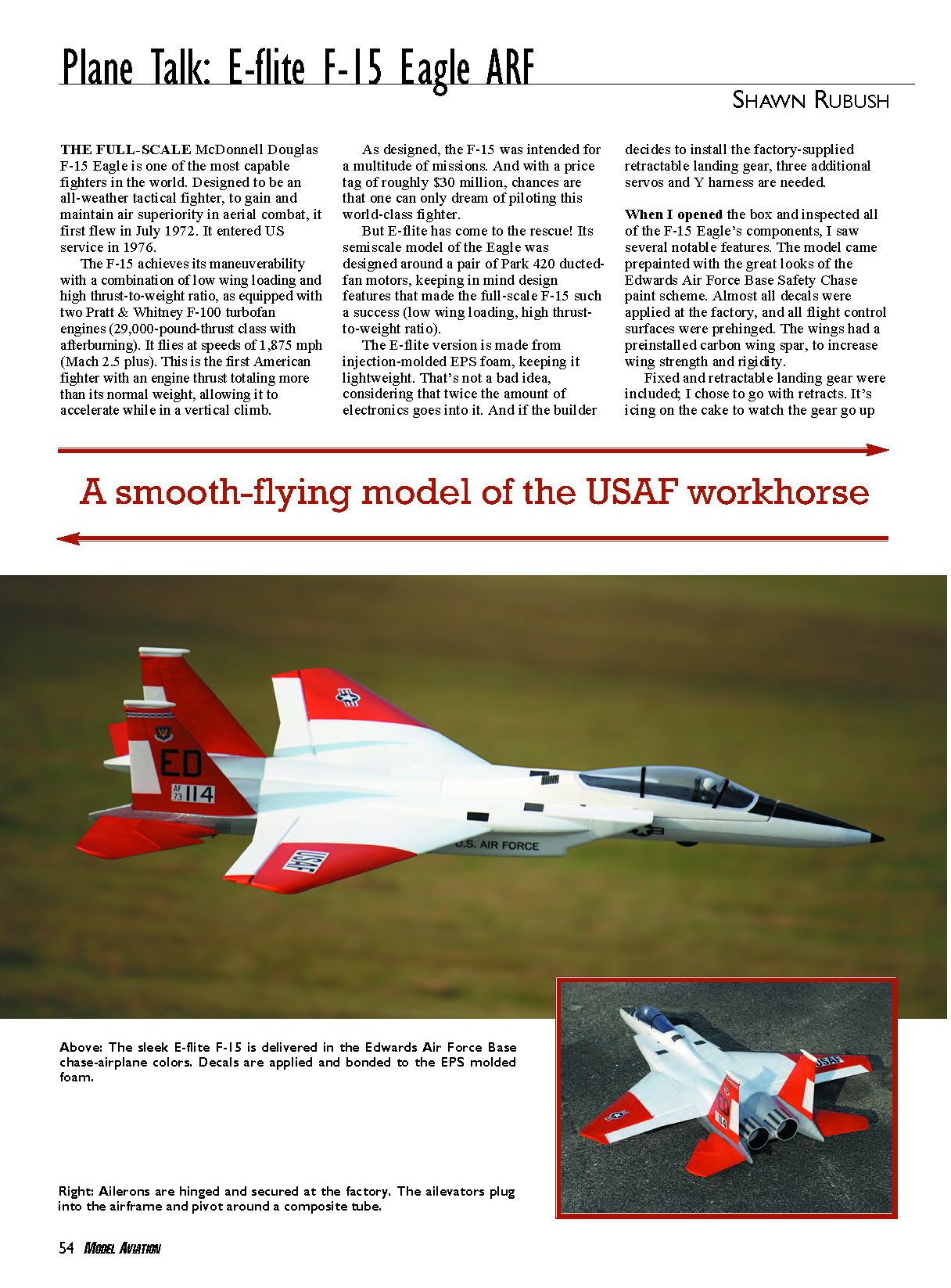
When I opened the box and inspected the F-15's components, several features stood out. The model came prepainted in the Edwards Air Force Base Safety Chase paint scheme. Almost all decals were applied at the factory, and all flight control surfaces were prehinged. The wings included a preinstalled carbon wing spar to increase wing strength and rigidity.
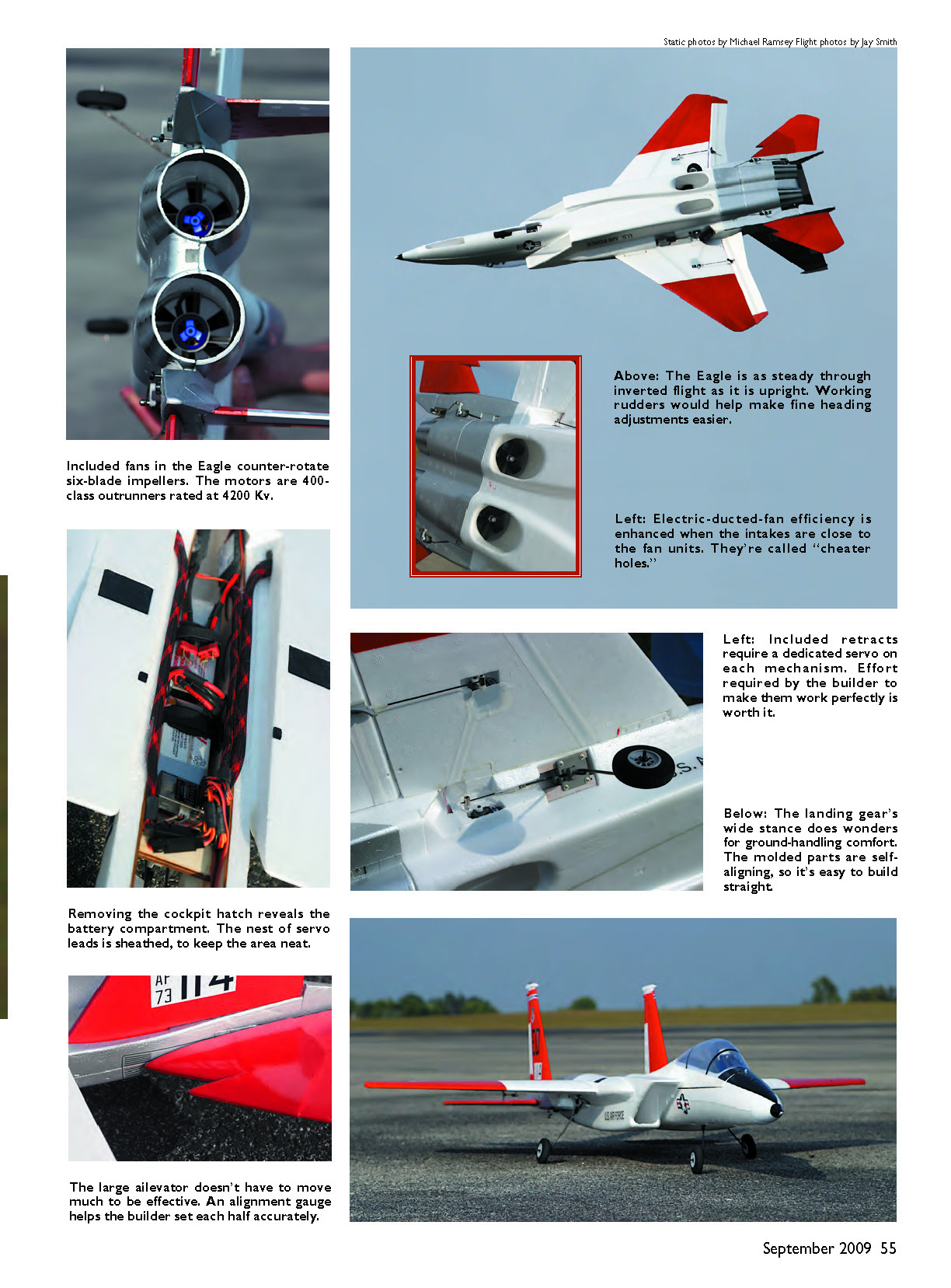
Fixed and retractable landing gear are included; I chose the retracts. It's icing on the cake to watch the gear go up on a flyby, adding to the scale appearance. Compared to other models I've built, the F-15 had a surprisingly low parts count. Having never built or flown a jet of any kind, I expected something more complex, but after briefly reading the manual my reservations were laid to rest. The instructions were well written, with step-by-step lists of required parts, tools, and adhesives, plus pictures showing intended results. Special notes for particular steps were included to ease assembly. One I particularly liked, at the beginning of the retract installation, explained how to set up retract programming using the Spektrum DX7 transmitter — extremely helpful since I'd never encountered that application before.
Construction
Before permanently installing electronics in any project, it's good practice to lay out and mock up all components. There are many benefits to making this one of the first steps in a build; centering servos is one of the most important. Nothing is more frustrating than trying to "gracefully" dig a servo out of a recessed pocket after gluing it in place. From experience, I've learned that not all servos are created equal — some do not mechanically center as well as others. Assigning channels and control horns on the bench makes final installation easier.
For the Eagle, I mocked up the servos in their positions and marked them with small pieces of tape to remember placement later. Fortunately, the Eagle has only two servos (ailerons) in a recessed pocket that require centering before installation. With the mock-up done, installing stabilizer servos was straightforward.
Installing the stabilizers brought up a concern: the stabilizer control-rod bushings in the fuselage are not parallel to each other because the tail sections' angles differ. This caused a slight bind in the control linkages. A simple solution was to insert a drill bit of the same size and carefully hand-drill the bushings for better alignment, micro-polish the stabilizer control rods, and apply graphite lubricant to both bushings and rods. A dab of cyanoacrylate on the inside surface of a bushing also helped eliminate binding. After those fixes, the recommended E-flite S75 servos managed the control surfaces without excessive resistance.
When installing the stabilator setscrews, you may dent the tail to access the screw, leaving unsightly indentations on each side. A cleaner approach is to make a small incision for Allen wrench clearance and glue it afterward to minimize damage.
Next I assembled and installed the motor/fan units. Before final assembly, I balanced both impellers after an initial motor test run — time well spent. I was impressed with the RPM. Take care not to squeeze the fan housing while running up the motor; the housing can easily distort and cause grinding. After setting proper impeller clearance and mounting the ducted-fan units in the fuselage, I rechecked clearances and did a little sanding where needed. Note: don't run motors inside where the decibel level can upset others.
Installing the retractable landing gear took more time than expected. The nose gear installed without issue, but the main gear retracts did not fit properly in the fuselage. The spring portion of the gear-strut wires had been wrapped in the opposite direction, causing them to rest outside the molded channel and contact the actuator arm. To correct this, I rotated the gear-strut wires for better clearance, moved the wires more inboard, clamped the spring portion in a vise, and tweaked them to adjust the toe of the wheels. I also removed a small portion forward of the wing-alignment tab so the gear would retract completely.
I installed the S75 servos slightly lower in the fuselage than shown in the manual and placed the servo control arm with the pushrod connector close to the fuselage. That improved actuator geometry, keeping the actuator arm and control rod more parallel to the fuselage throughout movement.
With aileron servos installed and the main wing panels attached, completing the electronics was the last step before radio setup. Keeping servo wires and the Y-harness neat inside the battery compartment aids battery access; I used a wire loom that allowed three leads through without removing connector ends, which gave the wiring a clean look. I did have to notch the canopy in the rear to improve the fit.
After setting control throws to the recommended rates, glue the vertical stabilizers in place. Even though I wanted to install them early, it was wise to save them for last — I lost count of how many times I flipped the F-15 during programming.
After programming, a quick balance check (with retracts up) was all that remained before the maiden flight. Only 1/2 ounce in the nose was needed to reach the factory-recommended balance point of 3 3/8 inches from the leading edge.
Pluses and Minuses
Pluses:
- Park 420 DF 3800 kV motors and 40-amp ESCs provide ample power to perform basic aerobatics and maneuvers common to the F-15; half throttle is sufficient for most flying.
- Decals and Edwards Air Force Base Safety Chase paint scheme were completed at the factory, saving build time.
- Optional retractable landing gear is included, giving you three options: none, fixed, or retracts.
Minuses:
- No rudder authority; attempted use produced no response.
- Retracts require re-engineering to fit and work properly; fuselage is predrilled for fixed landing gear.
- Supplied clevis on pushrods did not secure reliably.
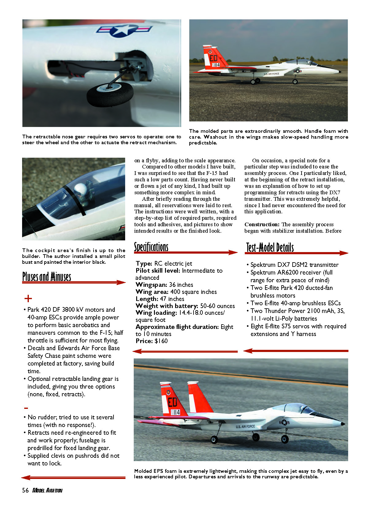
Specifications
- Type: RC electric jet
- Pilot skill level: Intermediate to advanced
- Wingspan: 36 inches
- Wing area: 400 square inches
- Length: 47 inches
- Weight with battery: 50–60 ounces
- Wing loading: 14.4–18.0 ounces/square foot
- Approximate flight duration: 8 to 10 minutes
- Price: $160
Test-Model Details
- Spektrum DX7 DSM2 transmitter
- Spektrum AR6200 receiver (full-range for extra peace of mind)
- Two E-flite Park 420 ducted-fan brushless motors
- Two E-flite 40-amp brushless ESCs
- Two Thunder Power 2100 mAh, 3S, 11.1-volt LiPo batteries
- Eight E-flite S75 servos with required extensions and Y-harness
Flying
After preflight checks, all systems were go. The Eagle taxied down the flightline nicely. At full throttle it wasted no time shortening the runway. With slight up-elevator the climbout was smooth and predictable. Once airborne, it was apparent that half throttle is sufficient for most maneuvers — unless you want a screaming flyby.
During the initial flight I found myself pushing up on the elevator while inverted. The recommended balance point left the F-15 a bit nose-heavy for my liking. After removing the 1/2 ounce of nose weight, the Eagle felt more neutral on the second flight. Switching to high rates made it more responsive with no unwanted characteristics.
The model performs basic aerobatics such as loops, rolls, and Split-S maneuvers with little effort. During a power stall late in a flight I reached the end of battery capacity and one ducted-fan unit shut down. The F-15 remained manageable on one engine and could be flown home. On a later flight the second motor quit, leaving a dead-stick condition; full up-elevator allowed a controlled descent and landing.
Overall, the E-flite F-15 Eagle is an enjoyable model for the ambitious pilot looking to take off with a first jet model.
Shawn Rubush [email protected]
Manufacturer/Distributor: E-flite / Horizon Hobby 4105 Fieldstone Rd. Champaign, IL 61822 (877) 504-0233 www.e-fliterc.com
Other Published Reviews:
- Hobby Merchandiser: July 2008
- RC Sport Flyer: October 2008
- R/C Report: October 2008
Transcribed from original scans by AI. Minor OCR errors may remain.

