
Plane Talk: E-flite Stearman PT-17 15e ARF
Jay Smith
An easy-to-fly replica of the 1930s US Army Air Corps primary trainer
There are many reasons to pick a certain model. It could be looks, flight performance, or a personal bond with an aircraft. For me this airplane fits into all three of those categories.
I have a true appreciation for biplanes, but the Stearman stands out. Maybe it's because it is powered by a radial engine that is uncovered and easy to admire. Or it could be the attractive US Army trim scheme that appeals to me as an Army veteran. The biggest reason might be the fact that I have flown in a full-scale PT-17 and experienced the freedom of open-cockpit flying with the same thrill of the brave men and women who learned to fly war machines with the help of that aircraft.
I have owned a couple of RC models of this prolific biplane; one was made from foam and the other was a conversion from a rubber-powered aircraft. Although both flew well, they left me wanting something larger and electric powered. So when I saw the E-flite version, I felt like Ralphie Parker from the movie A Christmas Story, with his desire for a Red Ryder BB Gun.
Fortunately for me, my enthusiasm for the project allowed me to get a Stearman without relying on my parents or Santa Claus.
I have always had good luck with E-flite airplanes and appreciate the work that goes into them to help ensure success, such as pre-applied decals and detailed, photo-illustrated manuals. The PT-17 is the sixth E-flite model I have owned and the first one since my review PT-19 that was featured in the Fall 2009 Park Pilot magazine.
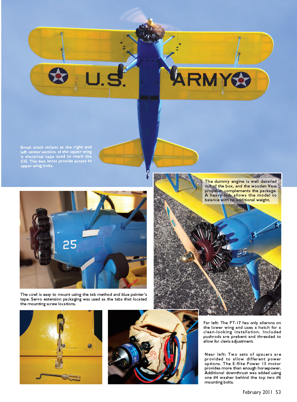
Access to the flight battery, receiver, and rudder and elevator servos is under the large magnetic hatch. Motor-mounting bolts protrude slightly from the back of the firewall, so foam was used as a barrier.
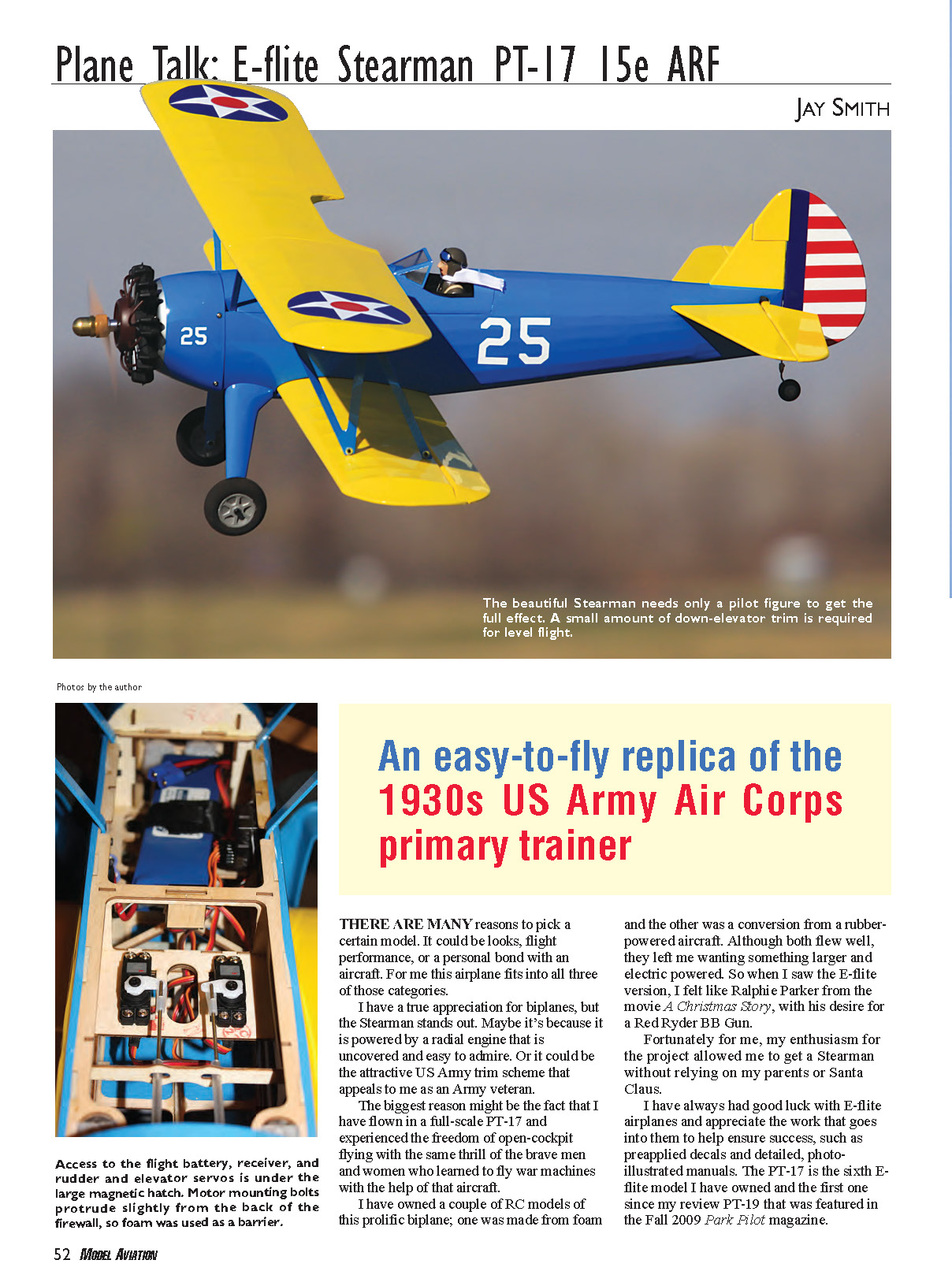
The beautiful Stearman needs only a pilot figure to get the full effect. A small amount of down-elevator trim is required for level flight.
Assembly
The Stearman arrived well packaged, and a quick inspection showed that everything was accounted for and undamaged. I like to completely unpack an airplane and let it sit overnight to allow it to adjust to climate changes before I touch up the covering.
I use that spare time to read the manual to gain an understanding of what is required to build and equip the model. The only thing worse than having to stop everything and run to the hobby shop is realizing that you need something when it's closed. The necessary materials were listed on page 3 of the manual.
The PT-17 needed little work on the covering; I removed a few wrinkles with a trim iron. The tape used to hold the ailerons and the foam blocks over the mounting lugs on the lower wing left a sticky residue, which I removed using CA debonder.
One of the first assembly steps requires you to remove the cockpit hatch, which is tabbed in the front and held down in the rear by some strong magnets. I was unable to take off the hatch without the help of a broken propeller under the rear edge. Removing the hatch roughly a half-dozen times while assembling and setting up the model was good practice.
Using the recommended servos ensured that they were simple to fit without modification. The instructions even describe the proper way to install the bushing in the grommet—from the bottom—which is commonly done incorrectly. The only deviation I made was to open the holes on the servo arms for the pushrods; I find that easier to do before mounting the servos.
Moving on to the tail, the builder gets a head start; the vertical stabilizer is already attached. Covering does need to be removed from the bottom of the horizontal stabilizer, which I did with the help of a soldering iron. The elevator must be inserted into the fuselage and then the horizontal stabilizer. After test-fitting the CA hinges, I glued them to the elevator before installing it in the fuselage.
Once both the elevator and horizontal stabilizer are slid into the fuselage, it's a bit challenging to insert the hinges into the stabilizer. Angling the elevator and installing the hinges in the order recommended in the manual helped. Another tip was to temporarily install the hinges in the stabilizer; they help guide the actual hinge.
The steerable tail wheel is well thought out and easy to install. The tail wheel shaft enters a predrilled hole in the fuselage. Then the shaft is glued into the rudder when it is attached to the stabilizer. The tail wheel assembly slides over the shaft and is held in place with a socket screw. Earlier versions of the Stearman have a slightly longer tail wheel shaft, which can be shortened to allow the tail wheel assembly to mount flush with the bottom of the fuselage.
The preassembled landing gear slides into slots on the side of the fuselage and is held in place with 6/32-inch Allen screws and washers. The aluminum-core gear struts fit nicely and provide a scale appearance. Although solidly attached, the gear will bend slightly on a less-than-perfect landing. Thread locker is used for the landing gear and all metal-to-metal fasteners.
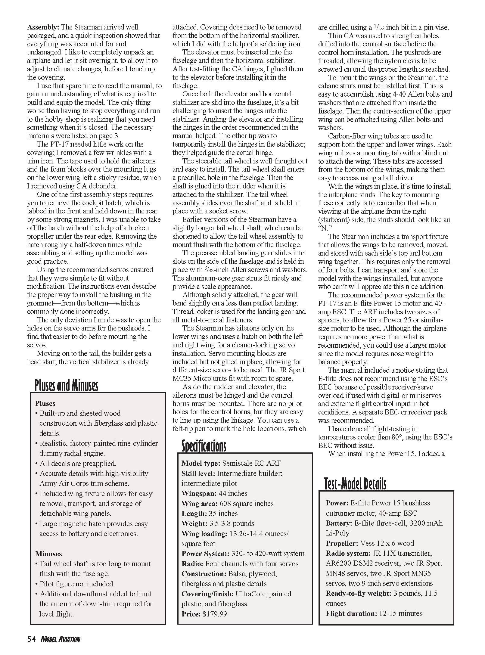
The Stearman has ailerons only on the lower wings and uses a hatch on both the left and right wing panels for a cleaner-looking servo installation. Servo mounting blocks are included but not glued in place, allowing for different-size servos to be used. The JR Sport MC35 Micro units fit with room to spare.
As with the rudder and elevator, the ailerons must be hinged and the control horns mounted. There are no pilot holes for the control horns, but they are easy to line up using the linkage. You can use a felt-tip pen to mark the hole locations, which are drilled using a 1/16-inch bit in a pin vise. Thin CA was used to strengthen holes drilled into the control surface before the control-horn installation. The pushrods are threaded, allowing the nylon clevis to be screwed on until the proper length is reached.
To mount the wings on the Stearman, the cabane struts must be installed first. This is easy to accomplish using 4-40 Allen bolts and washers that are attached from inside the fuselage. Then the center section of the upper wing can be attached using Allen bolts and washers.
Carbon-fiber wing tubes are used to support both the upper and lower wings. Each wing utilizes a mounting tab with a blind nut to attach the wing. These tabs are accessed from the bottom of the wings, making them easy to reach using a ball driver.
With the wings in place, it's time to install the interplane struts. The key to mounting these correctly is to remember that when viewing the airplane from the right (starboard) side, the struts should look like an "N."
The Stearman includes a transport fixture that allows the wings to be removed, moved, and stored with each side's top and bottom wing together. This requires only the removal of four bolts. I can transport and store the model with the wings installed, but anyone who can't will appreciate this nice addition.
Power system and recommended setup
The recommended power system for the PT-17 is an E-flite Power 15 motor and 40-amp ESC. The ARF includes two sizes of spacers to allow for a Power 25 or similar-size motor to be used. Although the airplane requires no more power than what is recommended, you could use a larger motor since the model requires nose weight to balance properly.
The manual included a notice stating that E-flite does not recommend using the ESC's BEC because of possible receiver/servo overload if used with digital or mini servos and extreme flight control input in hot conditions. A separate BEC or receiver pack was recommended. I have done all flight-testing in temperatures cooler than 80°F, using the ESC's BEC without issue.
When installing the Power 15, I added a small amount of additional downthrust using one #4 washer behind the top two #6 mounting bolts. The dummy radial engine is well detailed, and the wooden Vess propeller complements the package. A heavy hub allows the model to balance with no additional weight.
The ESC is mounted to the bottom of the motor box using Velcro. The cowl clears the ESC and wires with no problems and was easy to install using alignment templates I made from the servo extension packaging.
I found that installing the windscreens was omitted from the manual. The only things required to accomplish that were a small amount of canopy glue and blue painter's tape to hold the screens in place overnight. I also used canopy glue to adhere a military pilot (not included with the kit; available from Horizon Hobby) in place. While I was at it, I made a scarf for the figure using a small piece of silk from the craft store.
To complete the Stearman I chose a Vess wood propeller and a 2.5-ounce Great Planes Brass Heavy Spinner Nut to provide additional nose weight. According to the manual, 2–4 ounces is required to attain the recommended CG of 3.25–3.75 inches behind the upper wing leading edge. I marked both locations with a sliver of electrical tape so that I could feel them when balancing the model. I was happy to find that it fell precisely in the middle with the battery mounted all the way forward.
Throws were set per the manual. I was surprised to see only one set listed, as opposed to the high and low settings I am accustomed to getting. I also decided to use 20% exponential on all control throws to slightly soften my inputs.
The completed model is stunning. I don't know who was smiling more when I set the Stearman down on the runway: the dummy pilot in the cockpit or the one holding the transmitter.
Pluses and Minuses
Pluses
- Built-up and sheeted wood construction with fiberglass and plastic details.
- Realistic, factory-painted nine-cylinder dummy radial engine.
- All decals are pre-applied.
- Accurate details with high-visibility Army Air Corps trim scheme.
- Included wing fixture allows for easy removal, transport, and storage of detachable wing panels.
- Large magnetic hatch provides easy access to battery and electronics.
Minuses
- Tail wheel shaft is too long to mount flush with the fuselage.
- Pilot figure not included.
- Additional downthrust added to limit the amount of down-trim required for level flight.
Specifications
- Model type: Semiscale RC ARF
- Skill level: Intermediate builder; intermediate pilot
- Wingspan: 44 inches
- Wing area: 608 square inches
- Length: 35 inches
- Weight: 3.5–3.8 pounds
- Wing loading: 13.26–14.4 ounces/square foot
- Power System: 320- to 420-watt system
- Radio: Four channels with four servos
- Construction: Balsa, plywood, fiberglass and plastic details
- Covering/finish: UltraCote, painted plastic, and fiberglass
- Price: $179.99
Test-Model Details
- Power: E-flite Power 15 brushless outrunner motor, 40-amp ESC
- Battery: E-flite three-cell, 3200 mAh LiPo
- Propeller: Vess 12 x 6 wood
- Radio system: JR 11X transmitter, AR6200 DSM2 receiver, two JR Sport MN48 servos, two JR Sport MN35 servos, two 9-inch servo extensions
- Ready-to-fly weight: 3 pounds, 11.5 ounces
- Flight duration: 12–15 minutes
Flying
As does its full-scale counterpart, the E-flite Stearman gets airborne quickly. I have found that rapidly advancing the throttle to three-quarters provides ample power for takeoff, and only minor rudder correction is needed. No up-elevator is required to get the model airborne, even with the small amount of down-trim that was added on the first flight. By allowing the aircraft to take to the air on its own, you also help eliminate the chance of its pitching up aggressively on takeoff.
The Stearman is more than happy to cruise around with the throttle set to just above half. It's not finicky about whether turns are made with rudder, aileron, or both. Basic aerobatics are no issue, and the Stearman performs them in a scale manner. It can do nice, round loops, barrel rolls, and hammerhead turns all day long. Inverted flight is manageable with a touch of down pressure.
The PT-17 feels solid in the air. It has enough weight to handle the wind, yet its ample wing area allows it to fly slowly and it has a bit of a floaty feel. It will stall, signified by a slow drop of the wing when only up-elevator is applied, but it is easy to recover as long as you have a bit of altitude.
This model can land on the mains or as a three-pointer. The latter is recommended on either pavement or grass, because the lower airspeed won't encourage bouncing or the dreaded ground loop. The key to either landing is good airflow over the controls during the approach. Use the throttle and maintain power so that the controls stay effective until the wheels touch.
The E-flite PT-17 delivers on all levels. It provides a scale representation of full scale that anyone can enjoy directly out of the box. The flight characteristics are also in line with those of the full-scale aircraft and are nothing for an intermediate or better pilot to fear.
Construction of this model is well thought out, from easy access to the electronics and battery to provisions for simple removal of the wings for transport and storage. This biplane is hassle free.
Jay Smith [email protected]
Manufacturer/Distributor
E-flite/Horizon Hobby 4105 Fieldstone Rd. Champaign, IL 61822 (800) 338-4639 www.e-fliterc.com
Spektrum RC (217) 352-1913 www.spektrumrc.com
Sources
JR Radio (877) 504-0233 www.jrradios.com
Vess Propellers (919) 872-5611 www.vessaero.com
Transcribed from original scans by AI. Minor OCR errors may remain.

