
Plane Talk: ESM P-51B Mustang ARF
Tom Sullivan
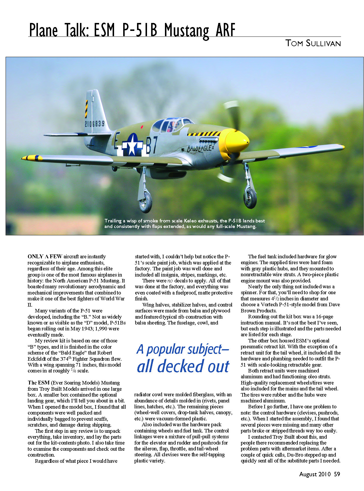
Only a few aircraft are instantly recognizable to airplane enthusiasts, regardless of their age. Among this elite group is one of the most famous airplanes in history: the North American P-51 Mustang. It boasted many revolutionary aerodynamic and mechanical improvements that combined to make it one of the best fighters of World War II.
Many variants of the P-51 were developed, including the “B.” Not as widely known or as visible as the “D” model, P-51Bs began rolling out in May 1943; 1,990 were eventually made.
My review kit is based on one of those “B” types and is finished in the color scheme of the “Bald Eagle” that Robert Eckfeldt of the 374th Fighter Squadron flew. With a wingspan of 71 inches, this model is roughly 1/6 scale.
Kit arrival and packaging
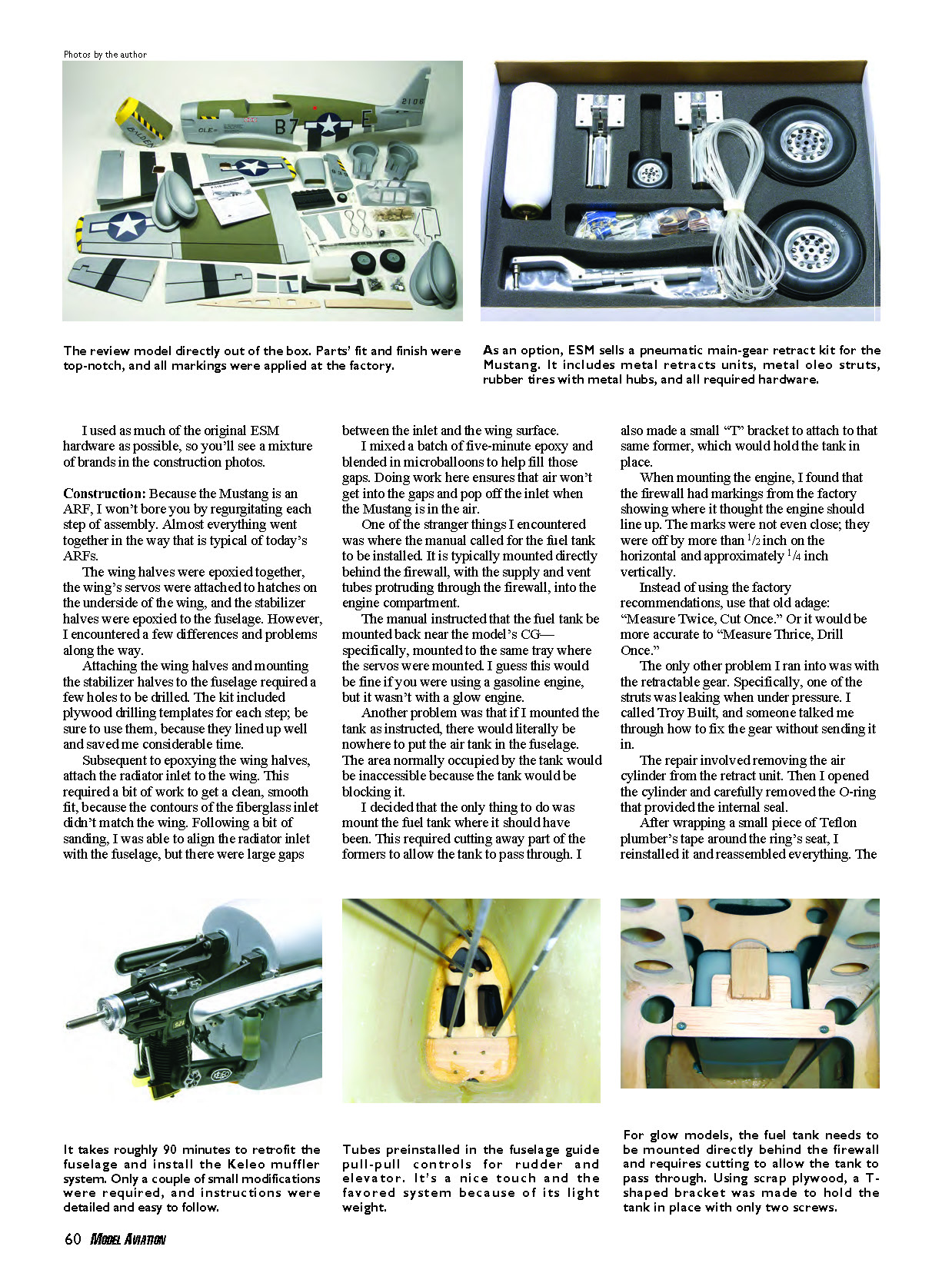
- The ESM (Ever Soaring Models) Mustang from Troy Built Models arrived in one large box; a smaller box contained the optional landing gear.
- All components were well packed and individually bagged to prevent scuffs, scratches, and shipping damage.
- A 16-page instruction manual was included. It's not the best I've seen, but each step is illustrated and the parts needed are listed for each stage.
Factory finish and included parts
- The model arrived factory-painted in a detailed scale paint job, including insignia, stripes, squadron markings and a matte fuelproof protective finish—no decals to apply.
- Wing halves, stabilizer halves, and control surfaces: balsa and plywood with typical rib construction and balsa sheeting.
- Fuselage, cowl, and radiator cowl: molded fiberglass with molded-in details (rivets, panel lines, hatches).
- Remaining pieces (wheel-well covers, drop-tank halves, canopy, etc.): vacuum-formed plastic.
- Hardware pack: wheels and fuel-tank hardware. The fuel tank included hardware for glow engines.
- Supplied tires: hard foam with gray plastic hubs on nonretractable wire struts (standard gear).
- Engine mount: two-piece plastic mount provided.
- Spinner: nearly the only thing not included. You need a 4-1/2-inch-diameter P-51–style spinner (for example, a Vortech from Dave Brown Products).
- Optional: ESM custom pneumatic retractable landing gear (sold separately) was available and comes in a separate box.
Optional pneumatic retract kit
- The optional pneumatic retract kit (other box) included all hardware and plumbing except a retract unit for the tail wheel.
- Retract units were machined aluminum with functioning oleo struts.
- High-quality replacement wheels/tires were included for mains and tail wheel (rubber tires, machined aluminum hubs).
Hardware concerns (important)
- Several control hardware items (clevises, pushrods, etc.) were missing or broke/stripped threads easily.
- Troy Built recommended replacing problem parts with aftermarket items. Du-Bro provided substitute parts promptly.
- I used as much original ESM hardware as possible, but you will likely want to plan on replacing some hardware with higher-quality aftermarket parts.
Construction
Because the Mustang is an ARF, most assembly followed typical ARF procedures.
- The wing halves were epoxied together.
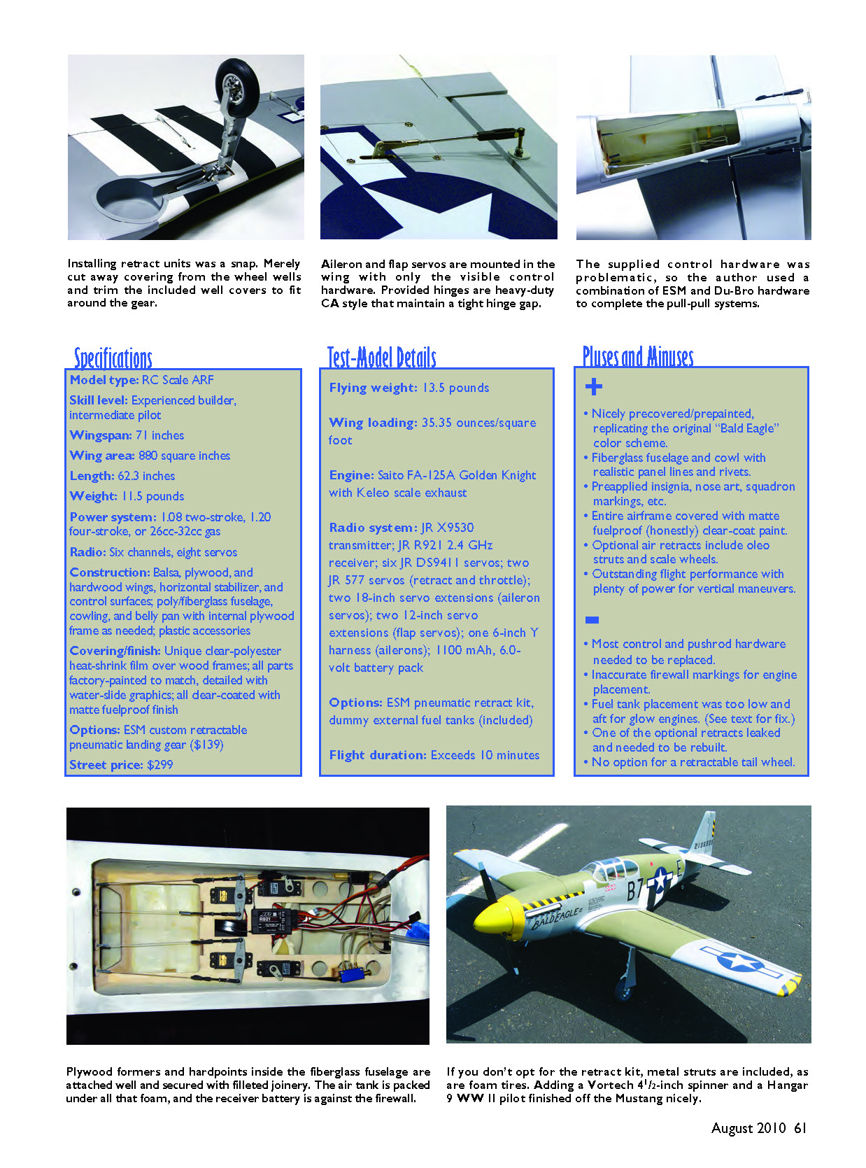
- Wing servos were attached to access hatches on the underside of the wing.
- Stabilizer halves were epoxied to the fuselage.
- The kit included plywood drilling templates for aligning and drilling mounting holes—use them; they lined up well and saved considerable time.
Radiator inlet fit
- The fiberglass radiator inlet contours did not match the wing, leaving large gaps after initial alignment.
- I sanded the inlet for a better fit, then mixed five-minute epoxy with microballoons and blended that into the gaps to prevent air ingress that could pop the inlet off in flight.
Fuel-tank placement
- The manual called for mounting the fuel tank back near the model's CG on the same tray as the servos. That location can be acceptable for gas engines, but it's wrong for glow engines.
- Mounted as instructed, there would be no room for the air tank and the tank would block access.
- I mounted the fuel tank where it should be for a glow engine—directly behind the firewall. This required cutting part of the formers to allow the tank to pass through and fabricating a small T-shaped plywood bracket to hold the tank in place with two screws.
Engine alignment and cowl work
- Factory firewall alignment marks were off by more than 1/2 inch horizontally and about 1/4 inch vertically. Don't trust those marks—measure carefully. "Measure twice (or thrice), drill once."
- Mounting a Saito 1.25 inverted engine required trimming the cowl so the rocker-arm covers could protrude from the underside.
- I opened the duct under the spinner as much as possible to allow cooling air into the cowl and enlarged rocker-arm clearance cuts so they extended back to about 3/4 inch from the firewall to help air escape.
Retract problem and fix
- One retract strut was leaking under pressure. Troy Built guided me through a field repair to avoid returning the unit.
- Repair: remove the air cylinder, extract the O-ring, wrap a small piece of Teflon plumber's tape around the ring's seat (increasing the effective diameter), then reinstall and reassemble. The repair sealed the leak.
Finishing touches
- Wing drop tanks: two vacuum-formed halves per tank—trim and mate carefully; they assemble nicely.
- Pilot figure and spinner not included—pilot found locally; spinner was a 4-1/2-inch Vortech aluminum spinner from Dave Brown Products. I had mine cut for a 16 x 8 Master Airscrew prop.
- Spinner painting: sand, prime with Rust-Oleum primer for metal, spray Rust-Oleum yellow (to match the cowl), finish with three coats of Rust-Oleum matte clear. The finish held up to starter use.
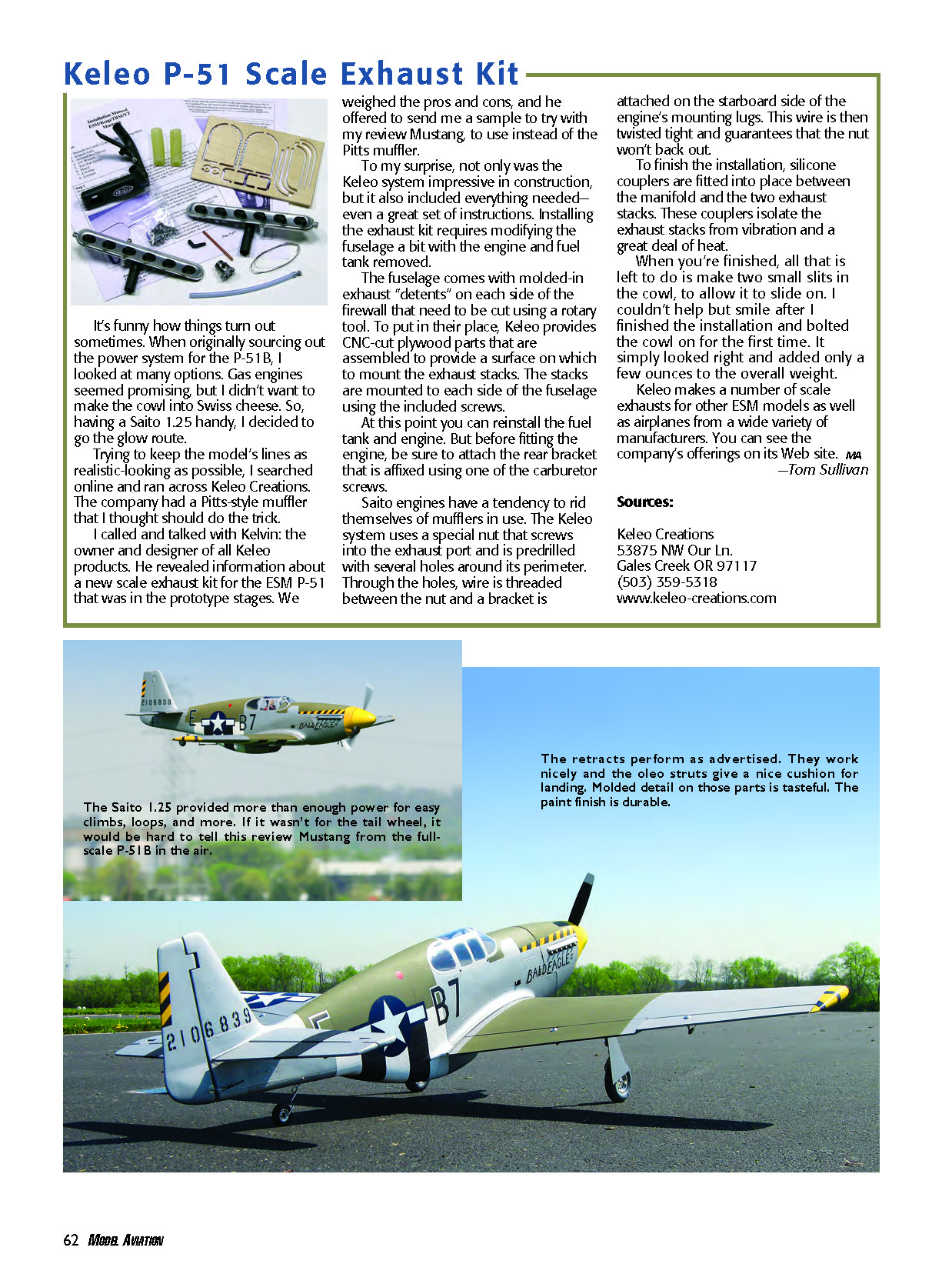
- The Keleo exhaust stacks add realistic smoke while taxiing and in flight. Because the stacks vent straight down the fuselage, keep cleaner handy and wipe down the fuselage and tail after each flight.
Weight and balance
- Finished flying weight: 13.5 pounds (the manual lists 11.5 pounds as the lightest possible weight without options such as retracts).
- CG ended up exactly where the manual indicated; I left it as shown.
Specifications
- Model type: RC Scale ARF
- Skill level: Experienced builder, intermediate pilot
- Wingspan: 71 inches
- Wing area: 880 square inches
- Length: 62.3 inches
- Weight (kit spec): 11.5 pounds
- Power system: 1.08 two-stroke, 1.20 four-stroke, or 26cc–32cc gas
- Radio: Six channels, eight servos
- Construction: Balsa, plywood, and hardwood wings, horizontal stabilizer, and control surfaces; poly/fiberglass fuselage, cowling, and belly pan with internal plywood frame as needed; plastic accessories
- Covering/finish: Clear-polyester heat-shrink film over wood frames; all parts factory-painted to match and detailed with water-slide graphics; all clear-coated with matte fuelproof finish
- Options: ESM custom retractable pneumatic landing gear ($139)
- Street price: $299
Test-Model Details
- Flying weight: 13.5 pounds
- Wing loading: 35.35 ounces/square foot
- Engine: Saito FA-125A Golden Knight with Keleo scale exhaust
- Radio system: JR X9530 transmitter; JR R921 2.4 GHz receiver; six JR DS9411 servos; two JR 577 servos (retract and throttle); two 18-inch servo extensions (ailerons); two 12-inch servo extensions (flaps); one 6-inch Y harness (ailerons); 1100 mAh, 6.0-volt battery pack
- Options installed: ESM pneumatic retract kit, dummy external fuel tanks (included)
- Flight duration: Exceeds 10 minutes
Pluses and Minuses
Pluses
- Nicely precovered and prepainted, accurately replicating the original "Bald Eagle" color scheme.
- Fiberglass fuselage and cowl with realistic panel lines and rivets.
- Preapplied insignia, nose art, and squadron markings—no decal work required.
- Entire airframe has a matte fuelproof clear-coat finish.
- Optional pneumatic retracts include oleo struts and scale wheels.
- Outstanding flight performance with plenty of power for vertical maneuvers.
Minuses
- Most control and pushrod hardware should be replaced with higher-quality aftermarket parts.
- Inaccurate factory firewall markings for engine placement.
- Fuel-tank placement in the manual is too low and aft for glow engines (requires relocation; see construction notes).
- One of the optional retracts leaked and needed a rebuild.
- No option for a retractable tail wheel.
Flying
For a warbird kit to capture my heart it needs to taxi well, look stable in the air, and be controllable on final approach.
- Ground handling: Taxiing was controllable even at high speeds and the model held on the mains until takeoff input was given.
- Takeoff and landing: The P-51B lands best and most consistently with flaps extended. Using flaps lets you maintain higher power settings during approach for better control.
- Air handling: On the maiden hop the controls felt too touchy for a short-coupled warbird. After adjusting radio programming and adding substantial exponential, the Mustang settled into a smooth, rail-like performance.
- Power: The Saito 1.25 provided excellent power for the 13.5-pound model—sufficient for loops, chandelles, wingovers, and Immelmanns. Half throttle gives a pleasant cruise speed and attractive low passes.
- Exhaust: The Keleo exhaust system looks and sounds great; it adds smoke while taxiing and in flight. Expect to clean the fuselage after flights due to exhaust soot.
- Durability: After a dozen flights the factory paint remained fuelproof and durable.
Recommendation: Consider adding the optional pneumatic retracts for improved scale appearance and durability versus standard wire gear. The Saito 1.25 with Keleo exhaust fit well in the cowl and provided excellent performance.
Overall, despite the need to replace some hardware and do minor retract maintenance, the ESM P-51B is a nicely detailed, great-flying warbird for the price.
Tom Sullivan [email protected]
Manufacturer/Distributor
- ESM/Troy Built Models
1650 Honore Ave. Sarasota, FL 34232 (941) 342-8685 www.troybuiltmodels.com
Sources
- Saito
(800) 338-4639 www.saitoengines.com
- JR
(800) 338-4639 www.jrradios.com
- Du-Bro Products
(800) 848-9411 www.dubro.com
- Dave Brown Products
(513) 738-1576 www.dbproducts.com
- Master Airscrew
Box 250 Rancho Cordova, CA 95741 www.masterairscrew.com
Transcribed from original scans by AI. Minor OCR errors may remain.

