
Plane Talk: Great Planes Cosmic Wind Minnow ARF
BY ROTH HEYES
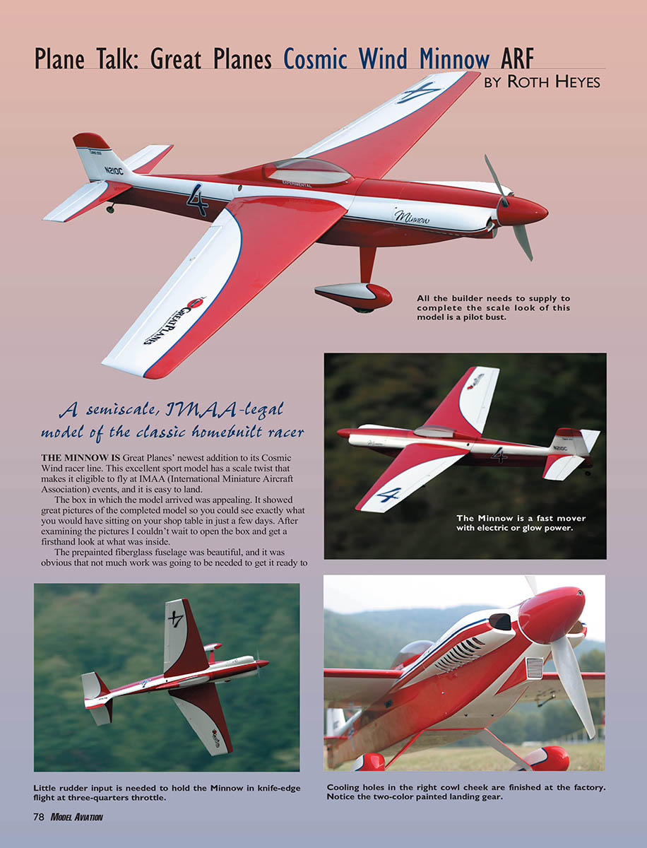
A semiscale, IMAA-legal model of the classic homebuilt racer
The Minnow is Great Planes' newest addition to its Cosmic Wind racer line. This excellent sport model has a scale twist that makes it eligible to fly at IMAA (International Miniature Aircraft Association) events, and it is easy to land.
The box in which the model arrived was appealing. It showed great pictures of the completed model so you could see exactly what you would have sitting on your shop table in just a few days. After examining the pictures I couldn't wait to open the box and get a firsthand look at what was inside.
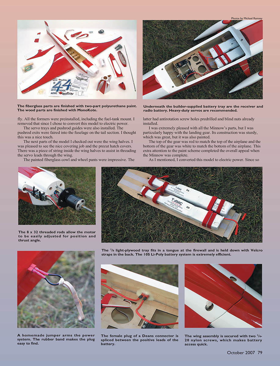
The prepainted fiberglass fuselage was beautiful, and it was obvious that not much work was going to be needed to get it ready to fly. All the formers were preinstalled, including the fuel-tank mount. I removed that since I chose to convert this model to electric power. The servo trays and pushrod guides were also installed. The pushrod exits were faired into the fuselage on the tail section. I thought this was a nice touch.
The next parts of the model I checked out were the wing halves. I was pleased to see the nice covering job and the precut hatch covers. There was a piece of string inside the wing halves to assist in threading the servo leads through the wing. The painted fiberglass cowl and wheel pants were impressive. The latter had antirotation screw holes predrilled and blind nuts already installed. I was extremely pleased with all the Minnow's parts, but I was particularly happy with the landing gear. Its construction was sturdy, which was great, but it was also painted. The top of the gear was red to match the top of the airplane and the bottom of the gear was white to match the bottom of the airplane. This extra attention to the paint scheme completed the overall appeal when the Minnow was complete.
As I mentioned, I converted this model to electric power. Since so much work was already completed on it, it was the perfect choice because build time was really not increased.
I needed to determine which motor, speed controller, and batteries would be required. After placing a quick phone call to Hobby Lobby I decided to use the Aero-naut Acro 40-4 motor (now distributed by Dymond Modelsport Ltd.). I picked the Castle Creations Phoenix-10HV speed controller because of the high-voltage capabilities and ease of use and setup. The Minnow was designed to be a racer, so I wanted the extra voltage from a 10S pack to go to good use. A large-diameter propeller with a deep pitch would get me the performance that is characteristic of the prototype.
I chose the Tanic Li-Poly batteries because of their high C rating. Brian Nakonechny at Tanic told me he could build two S53P 5400 mAh packs with the cells arranged sideways, permitting the 20C-discharge-rate packs to fit completely in the nose. That would leave the CG unaffected.
Once all the electric-conversion parts arrived, it was time to decide how to mount the motor on the firewall. I encountered my first conversion challenge at this point: I could not mount the short Acro motor directly on the firewall because it would not reach the front of the cowl.
I drew on my motor-mounting experience and decided I would need a few additional parts: four 12-inch lengths of 8/32 threaded rod, 12 sets of 8/32 nuts and washers, and a solid plate of 3 mm carbon fiber.
All those items were easy to get at The Home Depot except for the carbon-fiber plate. I ordered it online from Mach V Motorsports, which is an automotive shop that uses carbon fiber to make dashboards, hoods, etc.
It is important to take appropriate precautions when working with carbon fiber. Wear a respirator to keep the dust from getting into your lungs and make sure to cover your skin to minimize irritation.
I covered the carbon-fiber plate with masking tape so I could mark the areas that needed to be cut and drilled. I used a compass to draw a perfect 3-inch circle on the masking tape. I drilled the necessary holes to mount the motor to the plate and then drilled the holes that were required to attach the plate to the firewall. Once that was finished I removed the tape and attached the plate to the motor.
I screwed the threaded rods in place and marked the points on the firewall where the new holes were going to have to be drilled. Once the holes were made I attached the motor and carbon-fiber plate to the firewall using the 8/32 rods. I placed the cowl on the airplane and made fine adjustments to the threaded rods to make the spinner backplate line up with the cowl.
With the motor installation complete, it was time to decide where the speed controller should go. The cowl came with holes on the lower right cheek to allow for cooling the head on a glow engine, so I decided to use those to help keep the controller cool. I drilled four holes in the nose section (engine box) for two zip ties that would be used to hold the controller in place. (The cowl covered these holes, so they are invisible from the outside.)
The next step required some thought before jumping in. The batteries had to be installed in the Minnow's nose because of where the servo tray was located. To accomplish this I cut out the fuel-tank mount and installed a keeper block of wood in the nose. This allowed for a plate, with the batteries attached, to slide under it to keep the batteries from moving during flight.
I made the battery plate from 3/16 birch plywood for its strength and stiffness. I designed the tray to go from the Minnow's nose back to the servo tray and to be held in place with hook-and-loop fastener. I built another accessory mounting plate under the battery tray to accommodate the receiver, the 6-volt regulator, and the flight-pack battery.
I mentioned that I had the battery packs specially built to help keep the CG in check. The packs were built so one side had more cells than the other, and this worked great by having the heavier side to the back of the airplane and as far back as possible on the plate. With the packs located there, the balance was exactly where the instruction book called for it to be.
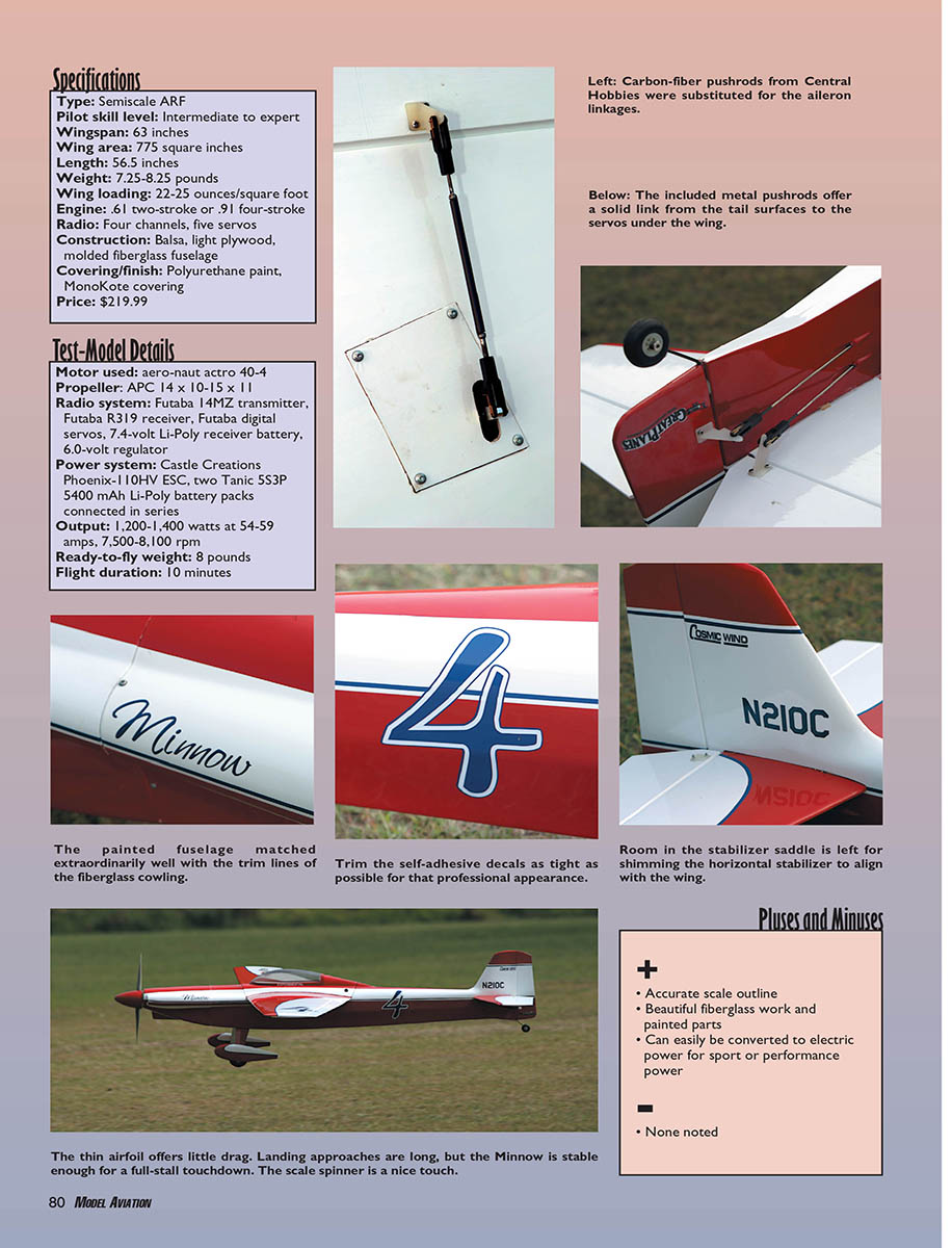
With the airplane balanced, it was time to set up the radio. I did this just as the directions called for on the high and low rates. However, I added a twist to the setup: I made a third high rate for the ailerons. With all the travels and dual rates set, the last step was to put in 30% exponential to slightly soften everything to my liking.
With the model’s mechanical steps complete, there were just a few finishing touches left. This ARF came with decals. When applied they looked great and enhanced the Minnow’s look. Applying all the letters was time-consuming but not too difficult, and the outcome was well worth it. Once all the letters were applied, I put on the spinner and took some pictures.
At this point the Minnow was ready to test-run, and I had to make sure the amp draw was acceptable. I turned on the transmitter followed by the receiver in the airplane, but even with the switch turned on the motor was not live since the onboard safety still needed to be plugged in. The onboard safety consisted of a simple jumper on the outside of the fuselage. The model was not armed until it was plugged in.
Once the airplane was armed, it was time to check the amps. The motor was pulling 58 amps on an APC 15 x 8E propeller. It felt like it was going to have tons of power.
Flying
With these final tests completed, I packed up the Minnow and headed to the field. When I pulled into the parking area the members started migrating to my truck to see what new and interesting aircraft I had. Everyone was impressed with this Great Planes release. Many commented on the fiberglass fuselage’s nice construction and how well the paint and MonoKote matched. I spent some time answering questions and explaining how I converted the Minnow to electric power, and then it was time to fly.
I performed a quick range and control test, and then I released the Minnow to taxi down the runway. At the end of the runway I completed one last control check and then slowly added power. The Minnow lifted off at half power and took to the sky. Immediately after takeoff I could tell that it was going to fly well. After a few clicks of up-elevator trim and one click of right aileron trim, the model was flying level and hands-off.
After a few passes to check the trim it was time to play around to see what the Minnow could do. I started with some loops and rolls and found it to be precise. It carved through the air extremely well—almost like an aerobatics airplane. I tried some more difficult maneuvers: four-point rolls, eight-point rolls, and some slow rolls. Wow! This airplane flew like it was on rails.
I set up for landing with a nice, long approach to allow the Minnow enough room to slow to touchdown speed. As it rolled out on final at a comfortable speed, just a hint of up-elevator was needed to raise the nose to the proper touchdown angle. After landing and taxiing back, I took out the batteries to see how they were doing. I was delighted to see the cell temperatures were only 110°F. That was great; it meant everything was working correctly and nothing was overheating or having to work too hard.
After determining that all the equipment was performing perfectly, I decided to make another flight to test the Minnow’s performance while increasing its speed. The second flight proved to be as exciting as the first. I applied half power for the takeoff, and the model held a nice climbout angle. It did a Split S from the climbout and headed back down the runway, and I increased the throttle to wide open. The model kept accelerating. I banked it to the left like a pylon turn, leveled it out, banked it to the left again, and took it back to level.
The Minnow looked great and performed extremely well at high speeds. It was graceful and carved its way around the track. After landing, people at the field told me how impressed they were with the airplane. It was quite a jet, a cinch to fly, and fully aerobatic. This is a terrific model!
Roth Heyes [email protected]
Test-Model Details
- Motor used: Aero-naut Acro 40-4
- Propeller: APC 14 x 10, 15 x 11 (also tested with APC 15 x 8E)
- Radio system: Futaba 14MZ transmitter, Futaba R319 receiver, Futaba digital servos, 7.4-volt Li-Poly receiver battery, 6.0-volt regulator
- Power system: Castle Creations Phoenix-10HV ESC, two Tanic S53P 5400 mAh Li-Poly battery packs connected in series
- Output: 1,200–1,400 watts at 54–59 amps, 7,500–8,100 rpm
- Ready-to-fly weight: 8 pounds
- Flight duration: 10 minutes
Specifications
- Type: Semiscale ARF
- Pilot skill level: Intermediate to expert
- Wingspan: 63 inches
- Wing area: 775 square inches
- Length: 56.5 inches
- Weight: 7.25–8.25 pounds
- Wing loading: 22–25 ounces/square foot
- Engine: .61 two-stroke or .91 four-stroke (recommended)
- Radio: Four channels, five servos
- Construction: Balsa, light plywood, molded fiberglass fuselage
- Covering/finish: Polyurethane paint, MonoKote covering
- Price: $219.99
Pluses and Minuses
- Accurate scale outline
- Beautiful fiberglass work and painted parts
- Can easily be converted to electric power for sport or performance power
- None noted
Manufacturer/Distributor
Great Planes Hobby Distributors Box 9021 Champaign, IL 61826 (217) 398-8970 www.greatplanes.com
Items Used in Review
- Futaba radio equipment — www.futaba-rc.com
- Castle Creations ESC — www.castlecreations.com
- Tanic Li-Poly batteries — www.tanicpacks.com
- Carbon-fiber plate — www.machv.com
- Aero-naut motor — www.rc-dymond.com
- Accessories — www.hobby-lobby.com
Other Review Sources
- Model Airplane News: February 2006
- RCMF: February 2005 and June 2006
- RC Report: December 2005
- Fly RC: October 2006
Transcribed from original scans by AI. Minor OCR errors may remain.

