
Plane Talk: Great Planes Giant Super Chipmunk ARF
Eric Henderson
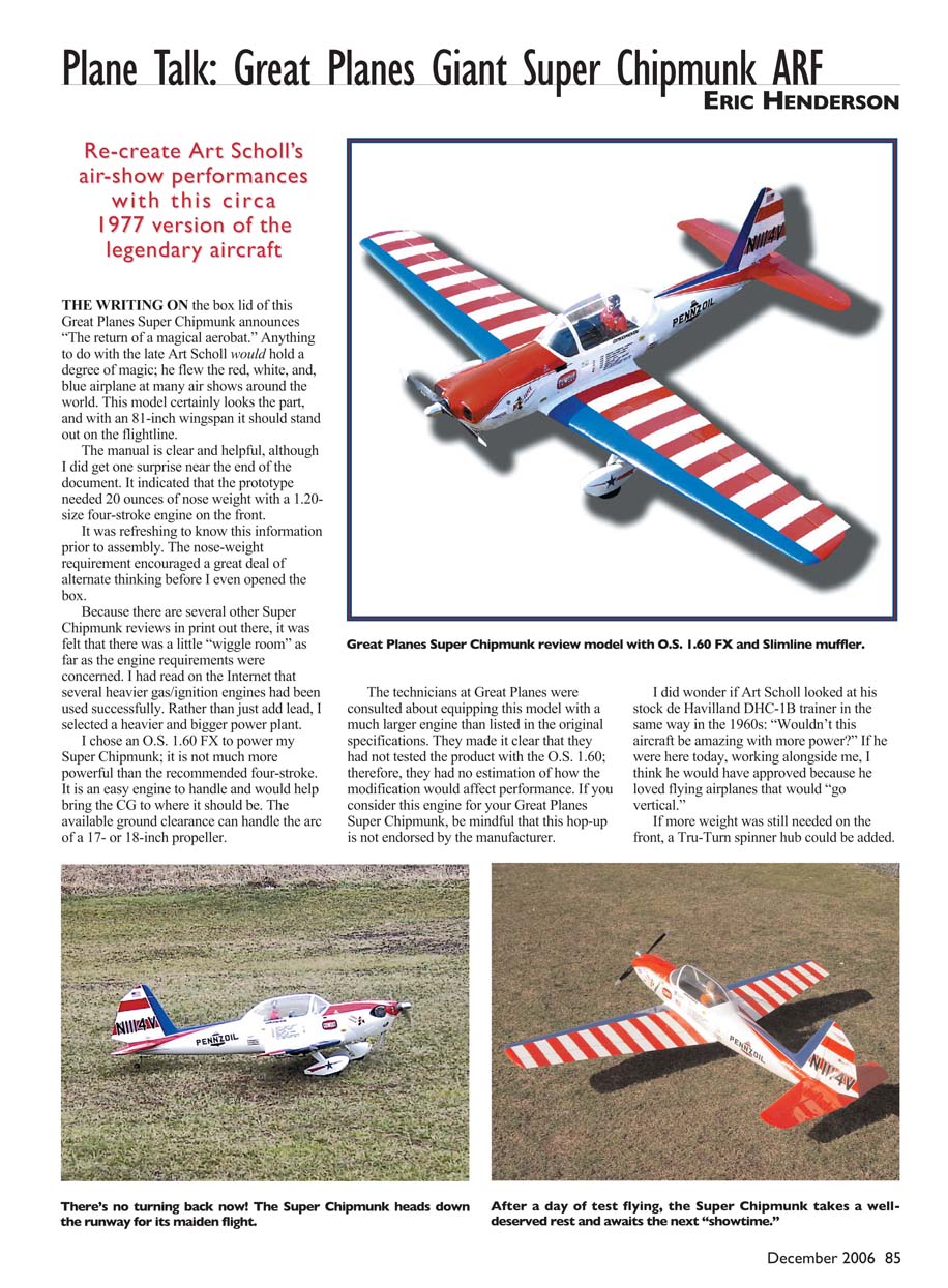
Re-create Art Scholl’s air-show performances with this circa 1977 version of the legendary aircraft
The writing on the box lid of this Great Planes Super Chipmunk announces “The return of a magical aerobat.” Anything to do with the late Art Scholl would hold a degree of magic; he flew the red, white, and blue airplane at many air shows around the world. This model certainly looks the part, and with an 81-inch wingspan it should stand out on the flightline.
The manual is clear and helpful, and it even indicated that the prototype needed 20 ounces of nose weight with a 1.20-size four-stroke engine on the front. Knowing that prior to assembly encouraged alternate thinking about power plants before I opened the box.
Because several other Super Chipmunk reviews exist, I felt there was some wiggle room regarding engine choice. I had read on the Internet that several heavier gas/ignition engines had been used successfully. Rather than just add lead, I selected a heavier and bigger power plant: an O.S. 1.60 FX. It is not much more powerful than the recommended four-stroke, is easy to handle, and helps bring the CG forward. The available ground clearance can handle the arc of a 17- or 18-inch propeller.
Great Planes technicians were consulted about equipping the model with a larger engine. They made it clear they had not tested the product with the O.S. 1.60 FX and could not estimate how the change would affect performance. If you consider this engine for your Super Chipmunk, be mindful this hop-up is not manufacturer-endorsed. If additional nose weight is needed, a Tru-Turn spinner hub or a heavier custom insert can be added. The kit includes plywood “doughnuts” to help line up the fiberglass cowl, and the spinner hub uses a full jam-nut configuration. Note that a propeller-hub adaptor is not the same as a one-piece spinner nut; it fits mechanically like a Tru-Turn spinner but is shaped more like a propeller nut.
To put even more functional weight forward, I selected a four-cell 2700 mAh Ni-Cd pack to drive the controls; the pack can be moved to fine-tune the CG.
The Great Planes Super Chipmunk is International Miniature Aircraft Association (IMAA)-legal and has a great-looking scale appearance. The builder provides the engine and radio, but almost everything else is included, and the model is covered with genuine Top Flite MonoKote.
Assembly
When I opened the box it was easy to see that most of the work (perhaps more than usual) was already done on this ARF. The fuselage and cowl are highly detailed fiberglass with many rivets and panel lines that make the model look realistic.
The wing is balsa-and-plywood and comes in three parts: two outer panels bolt to a single center section. The wing fastens to the wing saddle with two 1/4 x 20 thumbscrews. The two stabilizer halves plug onto the fuselage using two aluminum tubes; this plug-in stabilizer assembly saves the tricky job of aligning a glued stabilizer.
The canopy is clear with a white prepainted border. The hardware package includes Great Planes horns and clevises and a double pull-pull package—one for the rudder and one for the tail wheel.
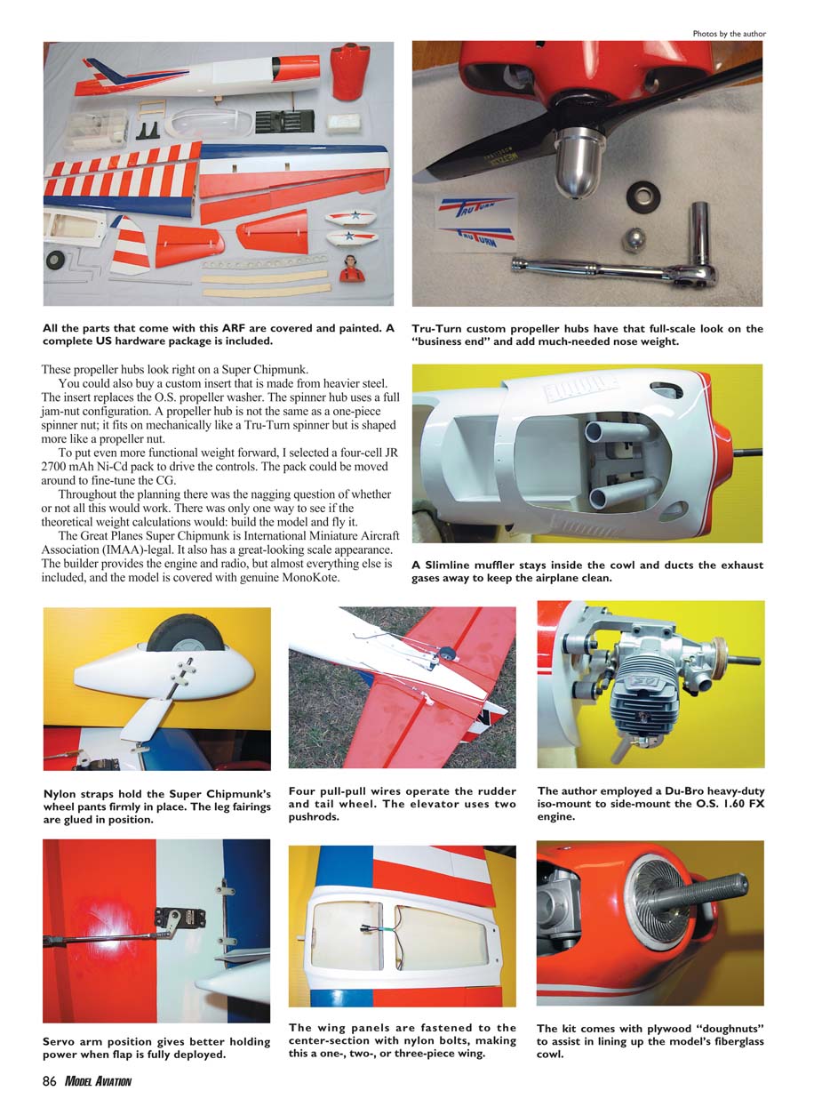
The fiberglass cowl is designed to completely cover an inverted 1.20 four-stroke engine; removing extra material was required to fit the larger O.S. 1.60 FX. The kit also includes a Slimline muffler that stays inside the cowl and ducts exhaust away to keep the fuselage clean.
I built the review model in the sequence outlined by the manual. The manual expects a certain amount of RC construction knowledge but contains many helpful hints for less experienced builders.
Detailed assembly notes and choices:
- I used two Y leads to keep programming and assembly simple: one Y for the ailerons and one for the flaps. This means both aileron servos and both flap servos are driven in parallel.
- I added servo extension leads to the aileron servos and fed them through the wing using the existing holes for the flap servos.
- The wing spar is a steel member sandwiched between two sheets of plywood, epoxied with 30-minute epoxy. The spar is removable so the wing can be disassembled for transport.
- With a Y lead the servo rotation direction is the same for each servo. For the ailerons the servo arms point out toward the wingtips. The flap servo arms are set so they pull the flaps down in the same direction; both arms point toward the same wingtip.
- Aileron and flap horns were fitted so the pushrods are roughly 90° to the control-surface hinge lines (a slight deviation from the manual but a personal preference).
- Aileron servo arms were set parallel to hinge lines and programmed for equal throws up and down. Flap arms were angled back toward the hinge line to reduce strain on the servo gears at full deflection.
- Because a Y lead does not allow transmitter-based centering of individual servos, centering was adjusted mechanically using threaded clevises; I left plenty of threaded rod in each clevis.
- The main landing gear uses a torsion-bar design with prebent heavy-duty 3/16-inch wire legs fitted into wooden blocks in the wing underside. The legs have a wide stance and are mounted with straps screwed to a plywood plate epoxied inside the wheel pants.
- Tires tend to spread under load and can “grab” wheel pants; I ground out the wheel openings in the pants for better clearance.
- Leg fairings are superglued and epoxied to the undercarriage legs, with a gap left between fairing and wing to allow leg movement.
- Stabilizer halves fit over tubes and were secured with 30-minute epoxy; I tinted the glue with red K&B part A paint to disguise the joint and to better match the fuselage colors.
- Elevators use Mylar hinges and have hard plywood plates for elevator horns. The elevator pushrods are two 36-inch 4-40 rods running in guide tubes; a single combining rod connects them to one elevator servo.
- The rudder uses a similar hinge method; a double horn connects the pull-pull wires to the rudder servo, and two more pull-pull wires connect the steerable tail wheel to the same servo arm. Each of the four wires has its own guide tube. Rudder wires are connected to the outer holes on the servo arm to give more rudder throw than tail-wheel throw.
- The firewall comes prestamped with datum lines that greatly help engine alignment.
- I used a Du-Bro heavy-duty iso-mount to side-mount the O.S. 1.60 FX.
Included/optional kit hardware and details:
- All kit parts are covered and painted; factory-applied Top Flite MonoKote finish.
- Complete U.S. hardware package included.
- Wing panels fasten to the center section with nylon bolts, allowing one-, two-, or three-piece wing configuration.
- Nylon straps hold the wheel pants. Leg fairings are glued in position.
- Tru-Turn custom propeller hubs provide a full-scale look and add useful nose weight. Custom heavier steel insert adaptors are available to replace the O.S. propeller washer if extra weight is desired.
- Plywood “doughnuts” are included to assist in lining up the fiberglass cowl.
- Four pull-pull wires operate the rudder and tail wheel; elevator uses two pushrods.
Pluses and Minuses
- Pluses:
- Two-piece wing and plug-in tail sections for easy transport and alignment.
- Many scale details—an example of how refined ARFs have become.
- Straight, well-fitting airframe as good as any expert builder could make.
- IMAA-legal and great scale appearance.
- Good value for the included hardware and finish.
- Minuses:
- The factory-specified upthrust was unnecessary and required trimming out.
- The cowl requires modification to fit larger-than-specified engines.
Test-Model Details
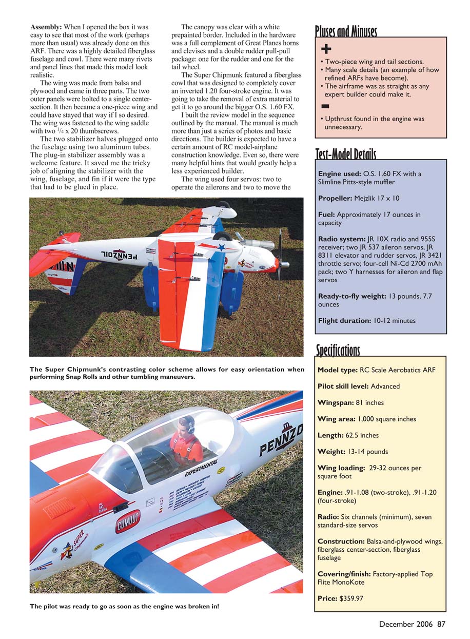
- Engine used: O.S. 1.60 FX with a Slimline Pitts-style muffler
- Propeller: Mejzlik 17 x 10
- Fuel: Approximately 17 ounces capacity
- Radio system: JR 10X radio and 955S receiver
- Servos: two JR 537 aileron servos, JR 8311 elevator and rudder servos, JR 3421 throttle servo
- Power: four-cell Ni-Cd 2700 mAh pack
- Wiring: two Y harnesses for aileron and flap servos
- Ready-to-fly weight: 13 lb 7.7 oz
- Flight duration: 10–12 minutes
Specifications
- Model type: RC Scale Aerobatics ARF
- Pilot skill level: Advanced
- Wingspan: 81 inches
- Wing area: 1,000 square inches
- Length: 62.5 inches
- Weight: 13–14 pounds
- Wing loading: 29–32 oz per square foot
- Engine: .91–1.08 cu in (two-stroke), .91–1.20 cu in (four-stroke) recommended; review model used O.S. 1.60 FX
- Radio: Six channels minimum; seven standard-size servos recommended
- Construction: Balsa-and-plywood wings, fiberglass center section, fiberglass fuselage
- Covering/finish: Factory-applied Top Flite MonoKote
- Price: $359.97
Flying
The O.S. 1.60 FX was new and required break-in. The Slimline Pitts muffler provided pressure to the fuel tank; priming was done with a couple of propeller flips while holding a finger over the carburetor. I used an electric starter for the first start, but after break-in the O.S. hand-started reliably with a single backward bump.
Because the engine has a piston ring, I ran a full tank on the ground to ensure the cowled powerplant could hold sustained full throttle without overheating. Break-in time was used to set a smooth transition from idle to mid-throttle; by the end of the tank the engine held full throttle with a slightly rich needle setting and never balked during transition tests.
The engine performed well with the 17 x 10 Mejzlik prop, 15% Powermaster fuel, and an O.S. F plug. The JR 10X radio was programmed with fail-safe: throttle to idle plus a touch of up-elevator in case of problems.
The Super Chipmunk taxied with authority. The colors on this rendition differ on the bottom, which helped orientation during aerobatic flight. On takeoff I advanced to roughly half-throttle; the O.S. 1.60 FX barked and responded willingly. The model tracked straight, the tail came up quickly, and a bump in the runway sent it out in a steep climb. Quite a bit of down-trim was needed for level flight; after a tiny left aileron trim it flew almost hands-off.
Flight characteristics and aerobatics:
- Trimming: Straight-and-level, up- and down-line checks required slight right-rudder trim for straight vertical climbs. Later this was mixed with throttle-cut.
- Vertical performance: The airplane sat in a vertical climb with little roll or yaw tendency; with throttle it would go vertical and stay there. It drifted slightly at the top.
- Stall and low-speed handling: Stall was predictable with some wing drop if recovered too slowly. Low-speed approach was benign; a little power and slight flare settled it onto the mains. Brakes were effective and the tail wheel kept tracking.
- Maneuverability: Loops were flat and round; rolls were crisp with moderate inputs; hammerheads and snaps were predictable. Enough power and control existed to perform vertical maneuvers and recoveries easily.
- Spins: Entered and performed with rudder and elevator only; rotation stopped after roughly one-quarter turn once controls were neutralized.
- Axial rolls and knife-edge: Axial rolls could be done slowly with small rudder/elevator inputs. In knife-edge there was a small pull to canopy; corrective mixes from rudder to aileron were required. Elevator down-trim was programmed to allow rudder-only knife-edge flight. Knife-edge required about 10% anti-rollout in both directions with rudder applied.
- Snaps: Inside and outside snaps worked well; the model tended to over-rotate unless the rudder was unloaded with roughly one-third of the snap remaining. A slight pull to canopy on the down-line needed about 2% down-elevator at low throttle.
- Flaps: Takeoff could be assisted by flaps—roughly half flap provided lift while maintaining solid aileron response. Approximately 1/4 inch down-elevator for half flap and 3/8 inch for full flap was effective.
- Performance in wind: Flew well in winds up to 15 mph and maintained precision and control harmony.
The O.S. 1.60 FX did not feel too powerful for this airframe; full-bore passes were confident and the model felt "locked" throughout. The Super Chipmunk handled both scale-looking formation-style flying and full aerobatics—making it suitable as a Sport Scale entry or a skill-building aerobatics platform.
Conclusion
Great Planes has produced a well-fitting ARF that flies like a good aerobat. With a sensible engine choice such as the O.S. 1.60 FX (or a recommended equivalent) and careful attention to balancing and rigging, the Super Chipmunk is a rewarding model for sport and aerobatic pilots. It looks great in the air, is IMAA-legal, comes with high-quality accessories, and is a strong value at roughly $360. Be prepared for the crowds this airplane can draw—it's the sort of model that can put you stage center at the club field.
Eric Henderson [email protected]
Manufacturer/Distributor
Great Planes Model Distributors Box 9021 Champaign, IL 61826 (217) 398-8970 www.greatplanes.com
Materials Used in Review
- Iso-Mount — www.dubro.com
- RC/56 by J&Z — www.zingerpropeller.com
- Mejzlik propeller — www.desertaircraft.com
- 1.60 FX engine — www.osengines.com
- 10X radio and servos — www.horizonhobby.com
- 15% fuel — www.powermasterfuels.com
- Pitts-style muffler — www.slimlineproducts.com
- Propeller hub adaptor nut — www.tru-turn.com
Transcribed from original scans by AI. Minor OCR errors may remain.

