

Plane Talk: Great Planes Matt Chapman CAP 580 46 ARF
Paul Vliet
Introduction / Pilot Background
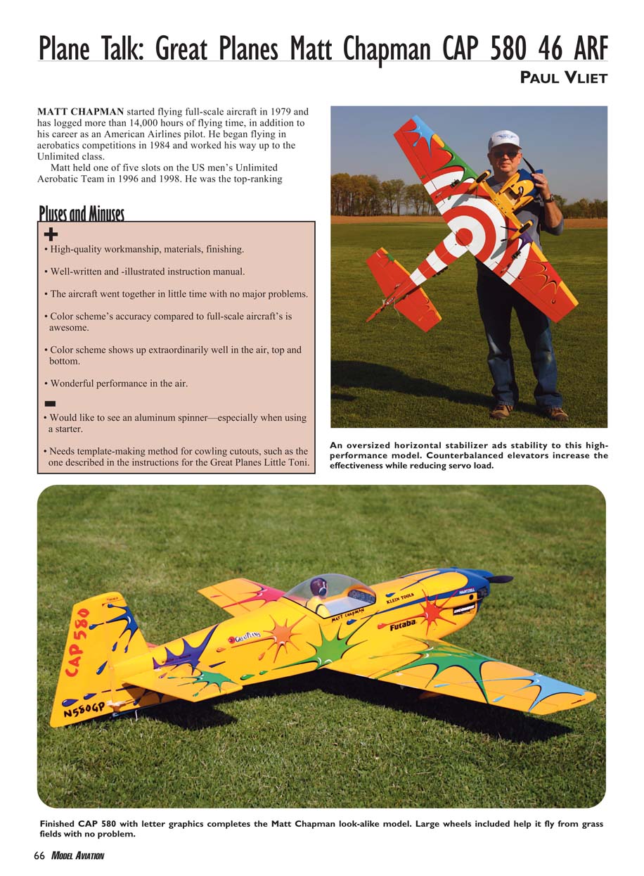
Matt Chapman started flying full-scale aircraft in 1979 and has logged more than 14,000 hours of flying time, in addition to his career as an American Airlines pilot. He began competing in aerobatics in 1984 and worked his way up to the Unlimited class. Matt held one of five slots on the U.S. men's Unlimited Aerobatic Team in 1996 and 1998, and he won a bronze medal at the 1998 World Aerobatic Championships in Slovakia. He has won the Hilliard Trophy (awarded to the top-finishing U.S. pilot at the world championships), the International Aerobatic Club championship trophy, and the Fond du Lac Cup. Matt has more than 20 years of air-show experience, is a member of CASPA (Championship Air Show Pilots Association), participates actively in the RC hobby, and is a member of Team Futaba.
The full-scale aircraft Great Planes modeled is the Matt Chapman CAP 580 — or, because of its spectacular paint job, the "CAP paint-ball special." It has a 24 ft wingspan, weighs about 1,300 lb, has a top speed of 240 mph, and a roll rate of 400°/sec. Great Planes produced two ARF versions of the CAP 580: a 1/3-scale model with a 99.5-inch wingspan and the 46- to 70-size version reviewed here with a 55.5-inch wingspan.
Pluses and Minuses
- High-quality workmanship, materials, and finishing.
- Well-written and well-illustrated instruction manual.
- The aircraft assembled quickly with no major problems.
- The color scheme's accuracy compared to the full-scale aircraft is excellent.
- The color scheme shows up extraordinarily well in the air, top and bottom.
- Wonderful performance in the air.
- Would like to see an aluminum spinner—especially helpful when using a starter.
- Needs a template-making method for cowling cutouts (for example, the method described in the instructions for the Great Planes Little Toni).
Specifications
Manufacturer Specifications
- Type: Sport scale aerobatic
- Pilot skill level: Intermediate
- Wingspan: 55.5 in
- Wing area: 562 sq in
- Length: 52.5 in
- Weight: 6.75–7.5 lb
- Wing loading: 28–30 oz/ft²
- Engine: .46–.61 two-stroke or 52–72 four-stroke
- Radio system: Four channels (minimum), five standard servos
- Construction: Laser-cut balsa and light-plywood airframe, fiberglass cowl and wheel pants, plastic canopy, aluminum landing gear
- Covering/finish: MonoKote (including all splat graphics); fuelproof paint for canopy frame, wheel pants, landing gear, cowl
- Price (street): $199.99
Test-Model Specifications
- Engine: O.S. FS-70 II Surpass
- Propeller: APC 13 x 6
- Radio equipment: Futaba 7CAP radio with five Futaba 3001 servos; 1100 mAh, 4.8V battery; one 6-inch extension; one Y harness
- Ready-to-fly weight: 6 lb 14.5 oz
- Wing loading: 28.3 oz/ft²
- Flight duration: Exceeds 10 minutes
Assembly and Construction Notes
Covering and finish
- As with most ARFs, a few spots needed reshrinking due to the transit from the Far East to the hobby shop. The test model had minimal wrinkles, easily removed with a covering iron and heat gun.
- The finish on the CAP is extremely detailed; the decal set adds the finishing touch. It would take considerable work to duplicate this finish on a scratch-built airframe.
Wing assembly
- Hinge the ailerons first. Use a straight pin inserted into the middle of each hinge to center them in their slots.
- Push pins into the center of each hinge until they contact the wing. Slide the aileron onto all hinges, remove the pins, and CA-glue the hinges on one side. Flip the wing and CA-glue the other side.
- Install the aileron servos and fish leads through the wing using the factory pull strings.
- If instructed, hold off installing aileron horns and pushrods until after joining the wing halves so the wing can lay flat.
- Join the wing halves using the plywood joiner in front and the dowel rod at the rear. Dry-fit first, checking fit and dihedral (3.375 in at the center of the leading-edge tip). If correct, disassemble, apply 30-minute epoxy, reassemble, weight down, and recheck. Use masking tape across the joint while the glue cures.
- Reinstall any servos removed for assembly.
Wing-bolt mounting plate
- Remove covering where the plate installs. Follow the manual's "Expert Tip" for removing covering; it works well.
Tail and control surfaces
- Mount the wing to the fuselage with the aircraft supported in a cradle. Insert the horizontal stabilizer into its slot.
- Measure from stabilizer tip to fuselage centerline on both sides; both sides should be equal.
- Measure from the wingtip trailing edge to the horizontal stabilizer leading edge tip on each side; they should match each other and match the stabilizer-to-centerline measurements.
- When satisfied, glue the horizontal stabilizer in place (thin CA works well because of the solid construction around the stabilizer pocket).
- Hinge the elevator halves using the same hinge method as the ailerons.
- Fit the vertical stabilizer in its slot, ensure it is perpendicular to the horizontal stabilizer, remove it, spread slow-curing epoxy in the slot, reinstall and prop until the glue sets.
- Install the tail-wheel wire and bracket, rudder, and assemble the landing gear per instructions. Grind a flat spot on the axle for the wheel-collar set screw.
Wheel pants and landing gear
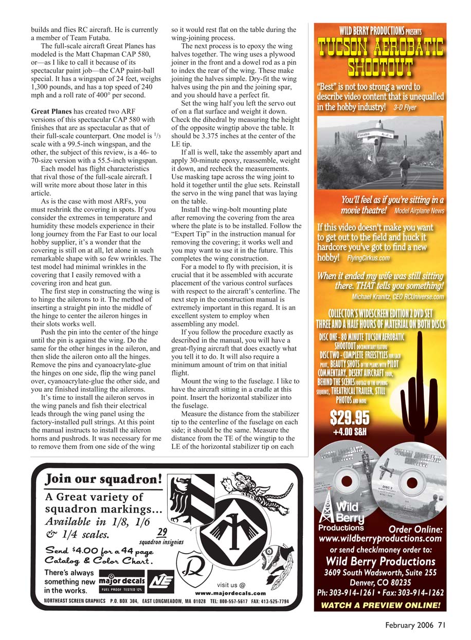
- Great Planes laminates a plywood mounting plate into the fiberglass wheel pant. The wheel pants and landing gear are predrilled and the pants have preinstalled blind nuts. Slip the pant over the wheel and bolt it in place—no alignment required.
Engine installation
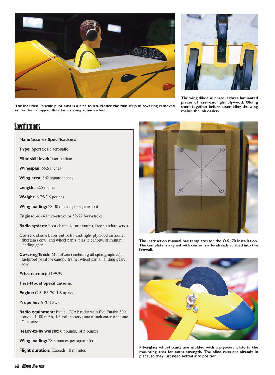
- The test model used the O.S. FS-70 II Surpass. Installation is straightforward: the firewall has centering marks and preset right- and down-thrust. Use the engine-mount template from the manual, tape it in place using guide marks, drill mounting holes, install blind nuts, and attach the engine mount.
- Position the engine 5 5/16 in from firewall to thrust washer for good cowl alignment. Install the fuel tank, throttle servo, and linkage per the manual.
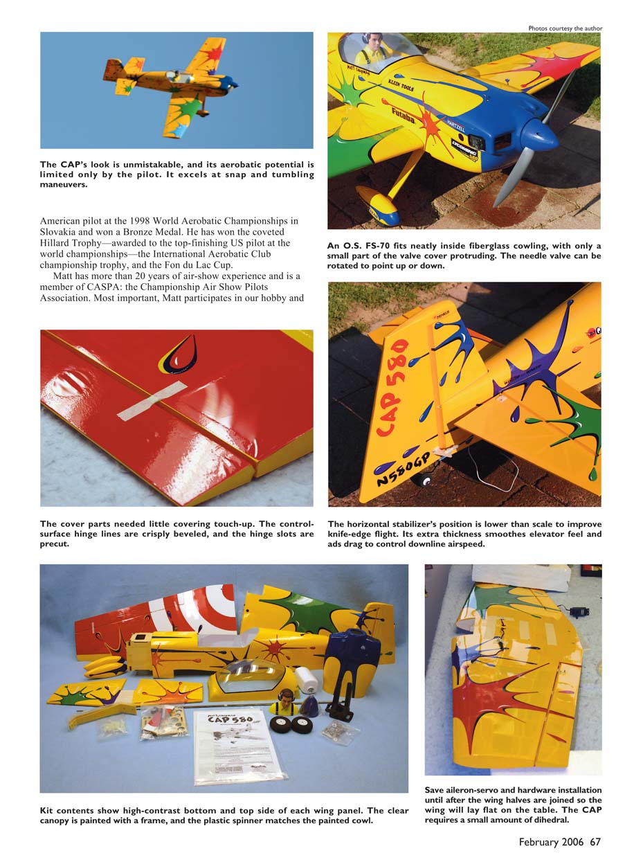
- The needle valve on the FS-70 can be rotated to point up or down; only a small part of the valve cover protrudes through the fiberglass cowl.
Cowling cutouts — template trick
- Install the hardwood cowl mounting blocks and make centering marks for mounting-screw holes per the manual.
- Cut two strips of construction paper about 1.5 in wide by 11 in long. Tape one strip over the engine-head and glow-driver area, and the other over the needle-valve area on the fuselage, behind the line where the rear of the cowling will sit.
- Mark and cut the engine-head and glow-driver shapes on the first strip while it is taped to the fuselage. Verify the fit over the engine head and glow driver.
- Mark and punch the needle-valve position on the other strip.
- Slip the cowling on; the paper templates will ride over the cowling and indicate the exact locations and shapes for the engine-head opening, glow-driver access, and needle-valve hole on the cowling. Transfer these shapes to the cowling and cut.
Radio and internal layout
- I installed radio equipment exactly as instructed. The receiver and battery pack locations in the manual balanced the model perfectly at the specified CG.
- There is ample room inside the fuselage. The receiver platform is designed to lock the fuel tank in place. Internal plywood parts have lightening holes and slots for Velcro straps to secure the receiver and battery pack.
Setup and Flying
Control setup
- I set control throws exactly as indicated in the manual and applied -18% exponential on all control surfaces. High rates were used for all controls on the first flight.
Flight characteristics
- The initial flight and subsequent flights were exceptional. The CAP responds with precision and predictability and performs maneuvers from Snap Rolls to Four-Point Rolls with ease.
- Ground handling is excellent, though there is a slight tendency to nose over on tall grass.
- The takeoff roll is straight with slight right rudder required to counter torque. Applying slight back pressure at rotation yields a gentle lift-off and smooth climbout.
- The model required minimal trim for hands-off flight — only a small right aileron trim.
- Inverted flight is nearly identical to upright flight, needing only slight down-elevator.
- The model climbs nearly vertically with the FS-70 four-stroke and performs stall turns and precision rolls well.
- Rudder authority is strong; long knife-edge flight posed no problem and Lomcevaks were achievable.
Landing
- On the test day there was a slight crosswind. I reduced throttle to half for downwind/crosswind, about one-third on final, and idle over the threshold. At roughly 2 ft off the ground I progressively added up-elevator until the CAP stalled into a three-point landing.
- Another technique used on subsequent flights was to come in slightly hot, let the mains touch first with elevator neutral, allow speed to bleed off, then ease in up-elevator to keep the tail down.
Conclusion
This aircraft is recommended for anyone who enjoys aerobatics or spirited sport flying. It is easy to assemble, looks impressive, and is a lot of fun to fly.
Paul L. Vliet [email protected]
Manufacturer: Great Planes Model Manufacturing Company Box 9021 Champaign, IL 61822 (217) 398-8970 www.greatplanes.com
Transcribed from original scans by AI. Minor OCR errors may remain.

