
Plane Talk: Great Planes Super Skybolt ARF
Al Morris
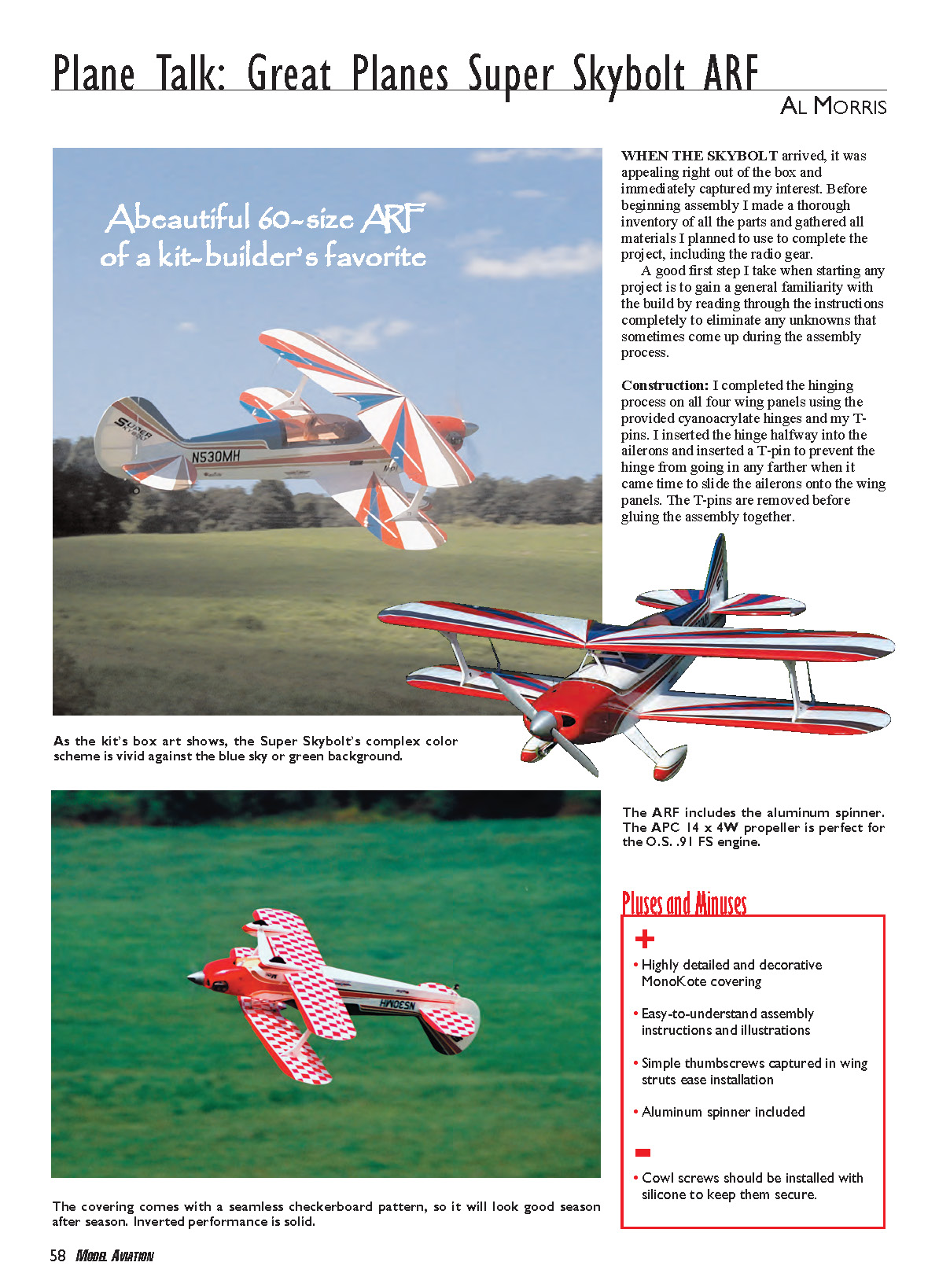
When the Skybolt arrived, it was appealing right out of the box and immediately captured my interest. Before beginning assembly I made a thorough inventory of all the parts and gathered all materials I planned to use to complete the project, including the radio gear.
A good first step I take when starting any project is to gain a general familiarity with the build by reading through the instructions completely to eliminate any unknowns that sometimes come up during the assembly process.
Construction
#### Wing assembly I completed the hinging process on all four wing panels using the provided cyanoacrylate hinges and T‑pins. I inserted each hinge halfway into the aileron and inserted a T‑pin to prevent the hinge from going in any further when it came time to slide the ailerons onto the wing panels. The T‑pins are removed before gluing the assembly together.
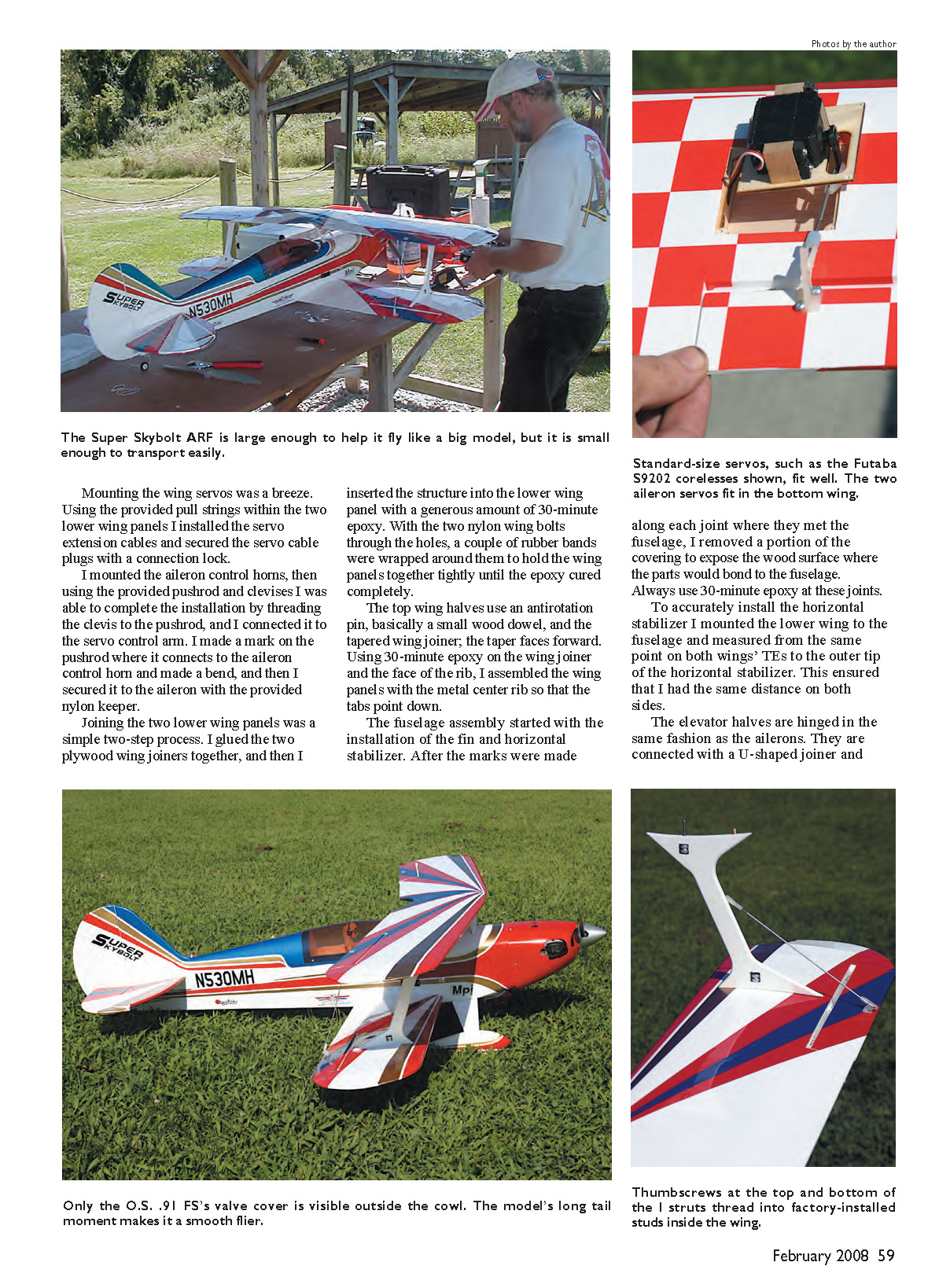
Mounting the wing servos was straightforward. Using the provided pull strings within the two lower wing panels I installed the servo extension cables and secured the servo cable plugs with a connection lock. I mounted the aileron control horns, then using the provided pushrod and clevises I completed the installation by threading the clevis onto the pushrod and connecting it to the servo control arm. I made a mark on the pushrod where it connects to the aileron control horn, made a bend, and secured it to the aileron with the provided nylon keeper.
Joining the two lower wing panels was a simple two‑step process. I glued the two plywood wing joiners together and then inserted the structure into the lower wing panel with a generous amount of 30‑minute epoxy. With the two nylon wing bolts through the holes, a couple of rubber bands were wrapped around them to hold the wing panels tightly until the epoxy cured completely.
The top wing halves use an antirotation pin (a small wood dowel) and a tapered wing joiner; the taper faces forward. Using 30‑minute epoxy on the wing joiner and the face of the rib, I assembled the wing panels with the metal center rib so that the tabs point down.
#### Fuselage, tail and control linkages Fuselage assembly started with the installation of the fin and horizontal stabilizer. After marking along each joint where they met the fuselage, I removed a portion of the covering to expose the wood surface where the parts would bond to the fuselage. Always use 30‑minute epoxy at these joints.
To accurately install the horizontal stabilizer I mounted the lower wing to the fuselage and measured from the same point on both wings’ trailing edges to the outer tip of the horizontal stabilizer. This ensured the same distance on both sides. The elevator halves are hinged in the same fashion as the ailerons; they are connected with a U‑shaped joiner and 30‑minute epoxy.
Installing the rudder and elevator servos went quickly; I only had to drill pilot holes for the mounting screws. The pushrods slid into the preinstalled guides once I removed the covering where they protruded through the fuselage side. After lining up each pushrod with its control surface, the control horns were secured with the provided hardware. I made a mark on each pushrod at the servo control arm and made a 90° bend. The rudder and elevator pushrods were secured with the provided nylon keepers. The two pushrods for the elevators are joined with two wheel collars, and the longer of the two pushrod wires connects to the servo.
The tail‑wheel assembly consisted of the tail gear, nylon retainer, tail‑gear bracket, and tail‑wheel mount. The tail‑wheel mount is a grommet type inserted into the hole in the rear portion of the fuselage, and the retainer is inserted into a pilot hole drilled into the bottom of the rudder. I secured the retainer and tail‑wheel mount in place with a bit of epoxy.
#### Landing gear and cabane struts Main landing‑gear installation went without a hitch. The main axles were mounted in place with nylon locking nuts, and the wheel pants slid in place and were secured with two 4‑40 Phillips‑head machine screws. I attached the main landing gear to the fuselage with six #4 screws.
Installing the cabane struts wasn't complicated. Each assembly slid into the slots within the fuselage. To get the holes aligned properly I used a piece of 2‑56 wire to hold the cabane in place while the 4‑40 mounting screws were inserted. The thumbscrews on the wing struts were a quick, efficient way to attach the wings. Using a little epoxy on the locating wooden pegs is a good idea.
The Skybolt came with a strip of hardwood to act as a lower wing shoulder for the nylon bolts. For a good joint I clamped this part in place while the epoxy cured and then drilled out the clearance holes.
Before attaching the wings to the fuselage I marked the center of the trailing edge of all four ailerons and installed the control horns used to couple the upper and lower ailerons. Each of those small control horns was trimmed down to the last hole for connection purposes. The metal center rib in the top wing attached to the fuselage cabane with two 4‑40 socket‑head screws and lock nuts. The linkage between the top and bottom ailerons was made from the supplied 2‑56 control rod and the nylon hardware.
#### Fuel system The three‑line fuel system came with all required hardware contained within the fuel tank. After the fuel tank was assembled I attached three lines approximately 12 inches in length, leaving the fill line available to come through the side of the fuselage for the fuel dot. I secured the fuel tank with a rubber band stretched across the back of it to the retainer tabs.
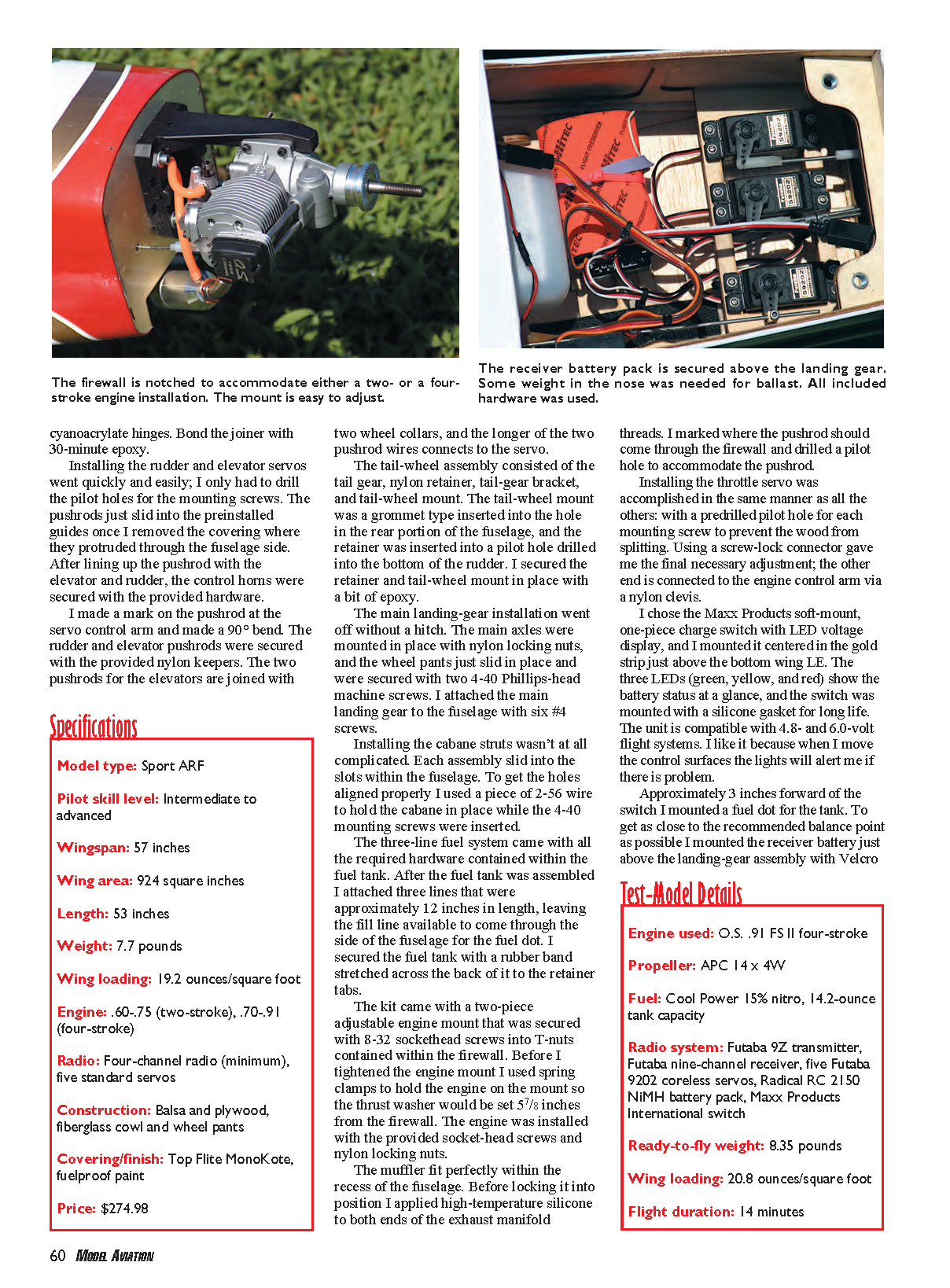
#### Engine and muffler installation The kit included a two‑piece adjustable engine mount that was secured with 8‑32 socket‑head screws into T‑nuts in the firewall. Before tightening the engine mount I used spring clamps to hold the engine onto the mount so the thrust washer would be set 5/8 inch from the firewall. The engine was installed with the provided socket‑head screws and nylon locking nuts.
The muffler fit perfectly within the fuselage recess. Before locking it into position I applied high‑temperature silicone to both ends of the exhaust manifold threads. I marked where the throttle pushrod should come through the firewall and drilled a pilot hole to accommodate the pushrod.
Installing the throttle servo was accomplished the same way as the others: predrilled pilot holes for each mounting screw to prevent wood from splitting. Using a screw‑lock connector gave the final necessary adjustment; the other end is connected to the engine control arm via a nylon clevis.
#### Electronics, switch and battery placement I chose the Maxx Products soft‑mount, one‑piece charge switch with LED voltage display and mounted it centered in the gold strip just above the bottom wing leading edge. The three LEDs (green, yellow, and red) show the battery status at a glance, and the switch was mounted with a silicone gasket for long life. The unit is compatible with 4.8‑ and 6.0‑volt flight systems. I like it because when I move the control surfaces the lights will alert me if there is a problem.
Approximately 3 inches forward of the switch I mounted a fuel dot for the tank. To get as close to the recommended balance point as possible I mounted the receiver battery just above the landing‑gear assembly with Velcro straps and impact foam to keep it from shifting position. I had to add only a couple ounces of lead weight to the bottom of the engine cowl to get the balance right on the CG.
#### Cowl and canopy The printed template for the engine cowl in the back of the instruction booklet provided a close approximation for the engine cutout. Once I cut the opening in the cowl I installed it using masking tape to properly center it and made final enlargements for a perfect fit. I installed the tinted cockpit canopy with the screws provided.
Setup and control throws
The control throws were set up with the recommended high and low rates, with 35% exponential programmed into only the high rate. I used the Futaba 9Z mixing to couple the aileron and rudder at 25%, which made the Skybolt perform like a simple sport airplane in the turns.
Ground testing and engine run
After several rotations of the propeller to prime the engine, the O.S. .91 fired up effortlessly and ran like a top. It's a good idea to check the high and low needle‑valve settings on the engine to make sure it will idle well and not go lean on takeoff.
Flight impressions
At less than half throttle, and a bit of back pressure, the Skybolt tracked perfectly down the runway and gently eased off the ground. The wings remained rock steady and level as the model climbed out to aerobatic altitude. I applied only a small amount of trim adjustment to achieve hands‑off straight‑and‑level flight.
One way to determine how close the balance point is: trim the airplane for straight‑and‑level flight and then roll it inverted. If it pitches down, it's slightly nose‑heavy; if it tends to pitch up, it's probably a little tail‑heavy.
Some biplanes, although balanced perfectly, are pitchy, leading you to believe they might be tail‑heavy when they're not. This problem may be a result of wing incidence.
The Skybolt is error‑proof right out of the box. Its mounting system gives a negative 2° on the top wing and a negative 1° on the lower wing, with the horizontal stabilizer set at 0°. This, combined with engine offset at 2° right thrust and 1° downthrust, gives the Skybolt excellent performance.
The Skybolt's top wing is swept back, which helps lower wind resistance while providing better penetration through the air. The lower wing is straight with approximately 12° of dihedral, giving more corrective in‑flight stability.
It amazed me how well and how stable this aircraft flew. I put the Skybolt through basic aerobatic maneuvers such as large loops, which required only a small amount of rudder to compensate for drift. The model performed spins and stalls in a predictable manner.
Rolling maneuvers were straight‑and‑level, and the Skybolt performed combination stunts such as inverted flight, Cuban eights, stall turns, split S's, knife‑edge flight, and outside loops with ease and more than ample power. Some 3‑D maneuvers, such as blenders, torque rolls, and flat spins, are possible as well.
The APC 14 x 4W is, without a doubt, the perfect propeller for this setup; it proved itself on takeoff and landing. Even if the approach was slightly high and fast, the propeller provided enough resistance to slow the model for a good landing.
The Great Planes Super Skybolt ARF is a sweetheart of a biplane and a joy to fly. It doesn't seem to have any bad habits and possesses stable slow‑flight characteristics. I was initially afraid it would tend to tip‑stall at low airspeeds, but to my surprise it was gentle and predictable.
This model is a gem and would make a great addition to anyone's hangar.
Al Morris [email protected]
Manufacturer/Distributor
- Great Planes
Box 9021 Champaign, IL 61826 (217) 398‑8970 www.greatplanes.com
Products Used in Review
- LED Switch (item 5470): Maxx Products International
(847) 438‑2233 www.maxxprod.com
- Servo extensions, Y harness, 2150 mAh NiMH battery: Radical RC
(937) 256‑7727 www.radicalrc.com
Other Review Sources
- 3D Flyer, November 2006
- Fly RC, December 2006
- Model Airplane News, December 2006
- R/C Report, June 2007
Transcribed from original scans by AI. Minor OCR errors may remain.

