
Plane Talk: Hangar 9 P-47D Thunderbolt 60 ARF
PAUL L. VLIET
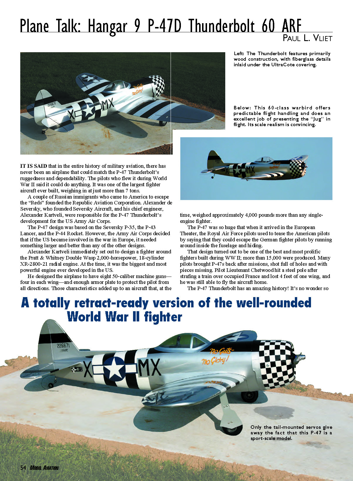
It is said that in the entire history of military aviation, there has never been an airplane that could match the P-47 Thunderbolt’s ruggedness and dependability. The pilots who flew it during World War II said it could do anything. It was one of the largest fighter aircraft ever built, weighing in at just more than 7 tons.
A couple of Russian immigrants who came to America to escape the “Reds” were responsible for much of the P-47’s lineage. Alexander de Seversky, who founded Seversky Aircraft, and his chief engineer, Alexander Kartveli, developed the design that ultimately led to the P-47 Thunderbolt for the U.S. Army Air Corps.
The P-47 design drew on earlier types such as the Seversky P-35, the P-43 Lancer, and the P-44 Rocket. When the Army Air Corps determined the U.S. might become involved in the war in Europe, it wanted a larger, more powerful fighter.
Kartveli set out to design a fighter around the Pratt & Whitney Double Wasp 2,000-horsepower, 18-cylinder XR-2800-21 radial engine — at the time, the biggest and most powerful engine developed in the U.S. He designed the airplane to carry eight .50-caliber machine guns (four in each wing) and to include armor plating to protect the pilot. Those features produced an aircraft that weighed roughly 4,000 pounds more than typical single-engine fighters of the era.
The P-47 was so huge that when it arrived in the European Theater, Royal Air Force pilots used to jokingly tell American pilots they could escape German fighters by running around inside the fuselage and hiding. That oversized, rugged design proved one of the best and most prolific fighters of WWII: more than 15,000 were produced. Many pilots returned P-47s after missions shot full of holes and missing pieces. For example, Lieutenant Chetwood struck a steel pole after strafing a train over occupied France, lost four feet of one wing, and still managed to fly the aircraft home.
The P-47 Thunderbolt has an amazing history. It’s no wonder so many modelers have immortalized the aircraft throughout the years, and now Hangar 9 brings a wonderful ARF version of this superior WWII fighter.
Pluses and Minuses
- Covering on the entire model is excellent in both detail and quality.
- All fiberglass work is high quality.
- Preinstalled landing-gear retract hardware.
- Landing gear retracts worked superbly.
- Excellent — and slightly lower than advertised — flying weight.
- Exceptional scale appearance.
- Terrific overall kit value.
- Ease of assembly and short assembly time.
- Complete, good-quality hardware package.
- Fantastic instruction manual.
Minuses
- Landing-gear control wires were too long and had to be shortened.
- Cowling looked canted to the right when installed (probably because of the right thrust built into the firewall).
- Wing dowels did not line up with the holes in the former; the author had to elongate both holes.
Construction
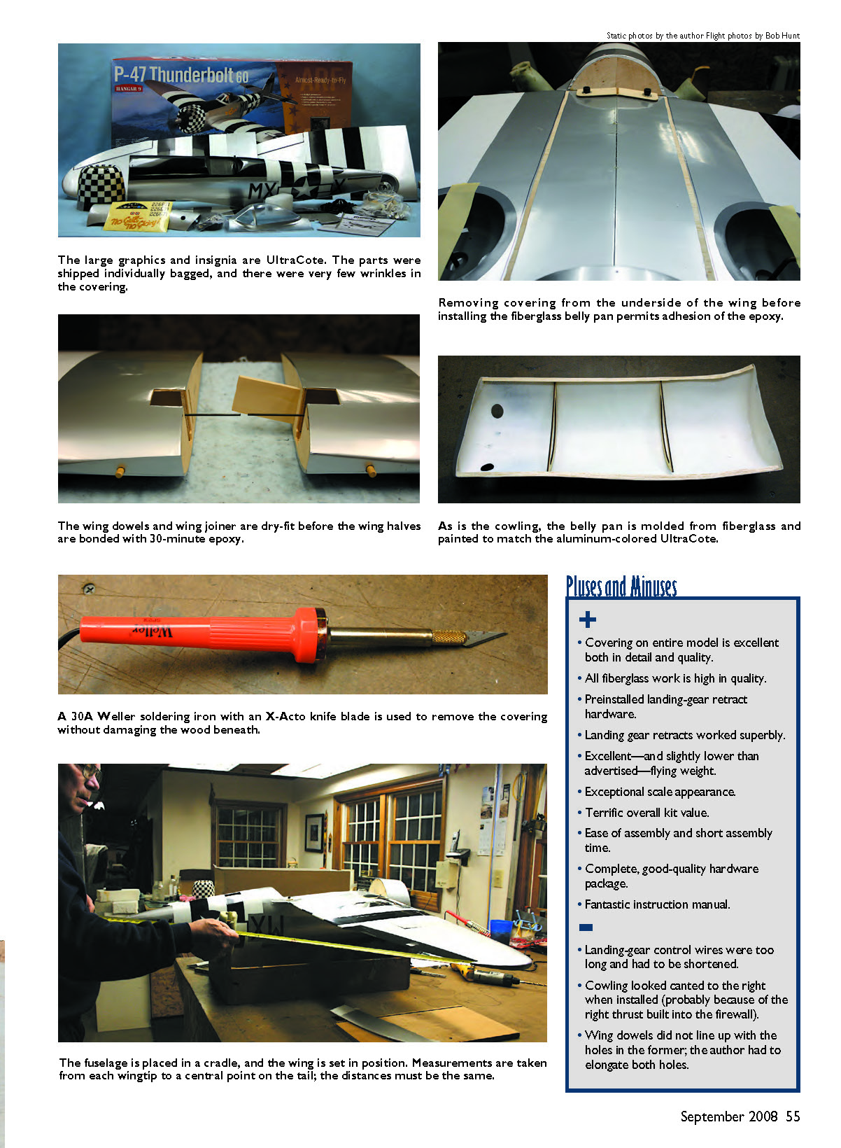
The kit arrives with all parts meticulously wrapped in sealed plastic bags. The aircraft is covered with UltraCote; you will find few wrinkles to iron, although there are always a few.
Joining the wing halves begins the project. I did a bit of light sanding to get the joiner to fit properly in the wing. Dry-fit the wing halves, and at that point check the length of the retract actuating wires — they were too long in the test model. I shortened them using a Dremel tool and a cutoff wheel. It’s easier to shorten the wires now than after the wing halves are permanently joined.
Remove any excess glue with paper towels and rubbing alcohol. Make sure there are no gaps between the center joint on the wing’s top and bottom surfaces. Place masking tape across the joint on both sides of the wing and set it aside until the glue has cured.
Remove the covering from the wing where the mounting-bolt plate is to be glued. I prefer to outline the area with a fine Sharpie and then remove the covering, leaving approximately 1/8 inch under the plate. I use a Weller soldering iron that can hold and heat a #11 X-Acto blade; a hot blade requires little pressure and lets you cut through the covering without damaging the wood.
I had to elongate both dowel holes to the outside of the saddle in the fuselage so I could insert the wing dowel pins. Mount the wing using the wing bolts.
Measure from the notch formed at the wingtip where the aileron goes to a central spot on the rear of the fuselage, as described in the instruction manual. The distance must be the same on both sides. The measurement on the test model was perfect.
Position the fiberglass belly pan on the wing and align the forward and aft edges with the fuselage. Use a Sharpie to mark the position of the belly pan’s outside edges when you are satisfied with the fit. Adhere the belly pan to the wing using 30-minute epoxy. The kit comes with two strips of covering roughly 1/4 inch wide by 1 foot long; iron these on the joint between the belly pan and the wing on both sides.
Make sure the stabilizer is centered side to side in the fuselage. Measure from a central position on the front of the fuselage to the tip of the stabilizer on each side. Make sure the distances are the same. With the aircraft upside-down in the cradle, measure the distance from each wingtip to the table and ensure they match. Also measure from the table to the surface of the horizontal stabilizer on each side; these must be identical.
The diagrams in the instruction manual cover these steps well and should be followed on this and any model. Remove the covering from the top and bottom sides of the horizontal stabilizer center-section, coat the center-section with 30-minute epoxy, and reinsert the stabilizer into its slot. Recheck all measurements and allow the glue to set.
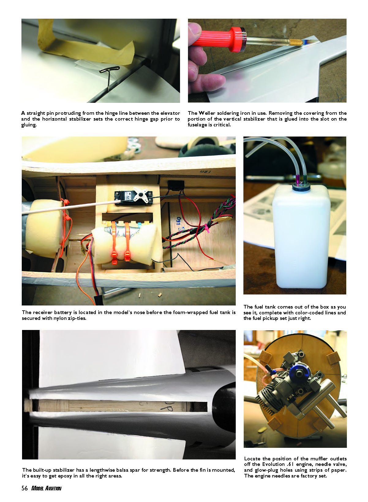
Remember to insert the U-shaped elevator joiner wire in the rear of the slot before gluing the horizontal stabilizer in place. Be careful not to get epoxy on this wire. Dry-fit the vertical stabilizer in the slot and make sure it is perpendicular to the horizontal stabilizer; then permanently install it.
Install both ailerons and the elevator halves using the provided hinges and secure them with thin cyanoacrylate. Use a small amount of 30-minute epoxy in the grooves and holes into which the elevator joiner wire goes. It’s a good idea to separate the elevator joiner wire from the horizontal stabilizer with waxed-paper strips while the epoxy sets so you don’t glue the joiner to the stabilizer.
Epoxy the tail-wheel wire into the groove and hole in the rudder. Attach the rudder to the vertical stabilizer using the provided hinges and thin cyanoacrylate. Tighten the collar on the tail wheel, screw the tailwheel bracket to the fuselage, and install the tail wheel.
Epoxy the retract-servo mounting beams and servo tray into the opening provided in the wing. Take care not to get epoxy on the retract wires during this process. Install the servo, the control arm, and the provided linkages. I did a temporary radio hookup to the retract servo to test the travel and make any necessary adjustments.
Follow the instructions for installing the two landing-gear bay doors to the landing gear. Test the retracts with the bay doors in place and make sure they lay flat when closed.
The kit accommodates either the Evolution .61 two-stroke (used in the test model) or the Saito 1.00 FA-AAC four-stroke provided in the kit. The only change I made was to use a Bisson muffler (item 5661 on the Bisson site) on the Evolution .61. Follow the instruction manual when installing these engines; everything was well thought out.
The fuel tank shipped with preinstalled plumbing. The fuel supply to the engine is color-coded red and the vent tube is coded green. Wrap foam around the tank and put it in the aircraft; I strapped it into position with a wire tie through the former and around the rear of the tank.
Control-surface servo installation is straightforward. Each elevator and rudder servo in the tail requires an 18-inch servo extension. Each aileron servo requires a 12-inch extension and a Y-harness. You will also need a 12-inch extension for the retract servo. The aileron servos mount to the servo bay covers and are hidden inside the wing. Preinstalled pull strings in the wing are used to fish the servo wires through. All control-surface linkages and the throttle linkage are provided.
The kit provides a wonderfully crafted, prepainted (with the checkerboard) fiberglass cowling and a dummy radial engine. Remove the dummy radial’s excess material around the cylinders before installing it in the cowling. Make sure the space between the dummy engine and the front of the cowl is even all the way around.
Center the cowling on the perimeter of the firewall while the opening in the dummy radial where the propeller shaft comes through is centered on the thrust washer. Secure the cowl with four screws driven into four hardwood blocks previously glued to the firewall.
To complete the cowl installation, make cutouts for the needle-valve extension, glow-driver hole, muffler-exhaust lines, and carburetor. I like to tape construction-paper strips to the fuselage behind the cowling and allow these strips to extend forward over the needle valve, glow plug, etc. Mark and cut the locations from the paper strips, then transfer and mark the positions of all cutouts on the cowl's surface.
Install the cockpit seat, dash decal, and canopy. I taped the canopy in place and marked its outline with a fine-point Sharpie. I removed approximately 1/4 inch of covering from around the inside perimeter (roughly 1/16 inch inside the marks) and then glued the canopy in place with 30-minute epoxy.
Flight-Testing
I ran in the new Evolution .61 at home before going to the club field for the test flights. The engine ran beautifully right out of the box, and after a couple of tanks of fuel I decided it was time to head out.
After a final range check of the radio, I taxied the Thunderbolt onto the runway, turned it into the wind, gave it some throttle, and the engine quit — it was too rich on the idle setting. After several attempts with the engine quitting, I finally got the P-47 airborne by bringing the throttle up slowly. Ground handling was excellent.
It took several clicks of down-elevator trim and right aileron trim to attain level flight the first time. After that, it flew superbly. The engine had plenty of power with more than ample vertical for tall stall turns. Four-point rolls were predictable and easy. Loop tracking was great. I tried a couple snap rolls, but they were more like barrel rolls. Inverted flight was stable.
Landing speed was slow, and the aircraft was steady on final. I carried slight up-elevator on the entire landing approach to maintain a stable attitude, adding throttle as necessary. A little flare at the end and the Thunderbolt settled in for a nice landing. The mechanical retracts functioned perfectly.
On the first landing I didn’t like my approach and tried to go around, but the engine quit because the idle setting was too rich. This resulted in a landing in the soybeans at the end of our field, but luckily there was no damage. The engine problem was corrected, and there was no trouble on subsequent landings.
All things considered, I highly recommend the Hangar 9 P-47 Thunderbolt 60 to anyone interested in a semiscale warbird with sport-model flight characteristics. This is an incredibly high-quality ARF for anyone with intermediate or better piloting skills.
MA
Paul L. Vliet [email protected]
Manufacturer/Distributor
Hangar 9 / Horizon Hobby, Inc. 4105 Fieldstone Rd. Champaign, IL 61822 (877) 504-0233 www.hangar-9.com
Sources
- Bisson Custom Mufflers — (705) 389-1156 — www.bissonmufflers.com
- Evolution Engines — (877) 504-0233 — www.evolutionengines.com
- JR — (877) 504-0233 — www.jrradios.com
Other Review Articles
- Fly RC: August 2006
- Flying Models: August 2006
- Model Airplane News: March 2006
- Quiet & Electric Flight: February 2006
- RCM&E: August 2006
- R/C Report: June 2006
Transcribed from original scans by AI. Minor OCR errors may remain.

