
Plane Talk: Hobby Club Models TopSky 1.1 DLG
Mike Skube
There is a great deal to be said about the excitement that a good discus-launched glider (DLG) produces when it performs well. Pilots who are new to hand launching need a model that has potential as well as the strength and durability to get past some of the roughness a newcomer may inflict on it. In addition, fliers want a sailplane that is fast and easy to put together.
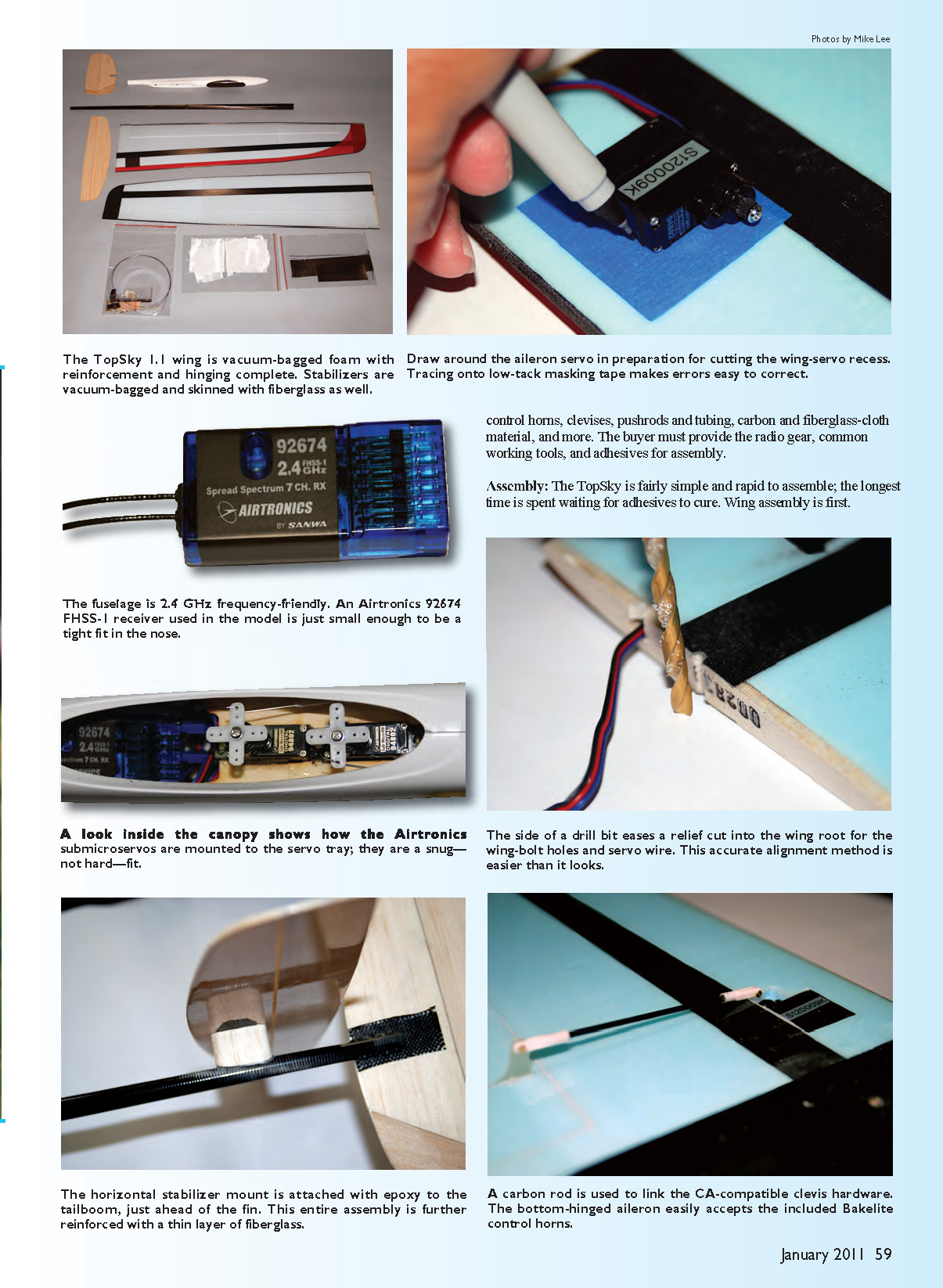
The TopSky 1.1 ARF fills that bill. This latest version of the original TopSky includes several improvements. The wing is a foam-core section with a vacuum-bagged, fiberglass-and-carbon-reinforced skin. The wing trailing edge is carbon reinforced to maintain stiffness and add strength. The vertical and horizontal stabilizers are vacuum-bagged, fiberglass-skinned balsa tailplanes.
An all-carbon tailboom mates to a fiberglass fuselage pod that features carbon reinforcement to withstand the rigors of a discus launch. The TopSky has a classic but contemporary style similar to a few other popular DLGs, with high-quality workmanship throughout. The model includes a well-endowed hardware outfit providing control horns, clevises, pushrods and tubing, carbon and fiberglass-cloth material, and more. The buyer must provide the radio gear, common working tools, and adhesives for assembly.
Assembly
The TopSky is fairly simple and rapid to assemble; the longest time is spent waiting for adhesives to cure. The kit comes with a photo-illustrated assembly manual that will smoothly carry you through construction. Despite the good guidance, building experience helps you get through it more quickly. (Editor’s note: A new instruction manual is included with all current models.)
The wing will be a single piece when completed but starts as halves. Ailerons arrive cut and hinged on the wings, so fitting aileron servos is done first. On the top of the wing you can see the black carbon pad where the servo bay will be on the bottom skin.
- Adhere a length of masking tape over the servo-bay area on the bottom wing skin and draw around the aileron servo.
- Pay attention to the position of the servo control arm and the servo wires so they face the correct way.
- Consider cutting off the aileron-servo mounting lugs; you won't use them and they will force you to cut a larger space in the wing.
- Using the outline, cut the wing skin and underlying foam core as deep as necessary to allow the servo to sit flush with the bottom wing-skin surface. Route the servo wires toward the wing root rib.
- Drill a hole from the root rib to the servo bay to allow the servo wires to snake through the wing to the root for connection to the fuselage later.
- Remove the servo wires from the stock plug to make the wire run easier; you won't use the stock connector.
When the temporary servo installation is complete, hold the wing half to the fuselage pod and mark and relieve the location of the wing bolts. Also provide a relief to allow the wing servo wires to poke through the wing center section. Do this for both wing components, then join the wing halves using epoxy.
The correct dihedral angle is set by the wing root ribs, so mate them evenly. When the epoxy has fully cured, finish the wing by adding the center-section reinforcement. The kit provides a choice of fiberglass or carbon-fiber cloth for that job — choose carbon cloth if you expect to toss hard. The wing is then finished for now.
At the tail, mate the vertical fin and rudder to the tailboom. The fin is notched to fit the tailboom but you will likely need to slot the tailboom a bit for a complete fit. Slice the tailboom as needed, fit the fin, and adhere in place. Use epoxy to attach a layer of fiberglass or carbon fabric to the joint for reinforcement.
Attach the tailboom to the fuselage pod after drilling through the wing hold-down bolt holes and cutting the wire-access hole to the fuselage. Mount the wing to the pod, level the wing on the workbench, then mate the tailboom (with the fin attached) to the pod to ensure proper nose-to-tail and wing-to-fin alignment. Make the joint using slow-set epoxy and allow it to cure overnight.
The horizontal stabilizer requires a small balsa stabilizer-mount platform that the kit provides in raw form; sand it to shape, then epoxy it to the stabilizer. Level the wings and glue the stabilizer assembly to the tailboom. Sand the tailboom where the joint will be made to ensure good bonding and further reinforce the joint with fiberglass cloth and epoxy.
The inner fuselage has plenty of space for modern submicro servos. A laser-cut plywood servo tray is provided and arranges the servos in a tandem configuration. Set the tray in place using RTV silicone adhesive (or any adhesive compatible with fiberglass).
The kit includes steel pushrods that run inside thin Teflon tubing. Drill through the rear of the lower wing-saddle area so the tubes lay directly on the tailboom after they exit the pod. Hold the tubing in place with black vinyl tape (best applied with the steel pushrod inside the tubing). Install control horns for the rudder and elevator and mate the pushrods to both servos and tailplanes.
The kit provides a throwing-peg option: a round tube peg and a carbon blade. Cut the tube peg down to suit your hand; sand the carbon blade edges smooth for handling if you choose it.
Control Throws
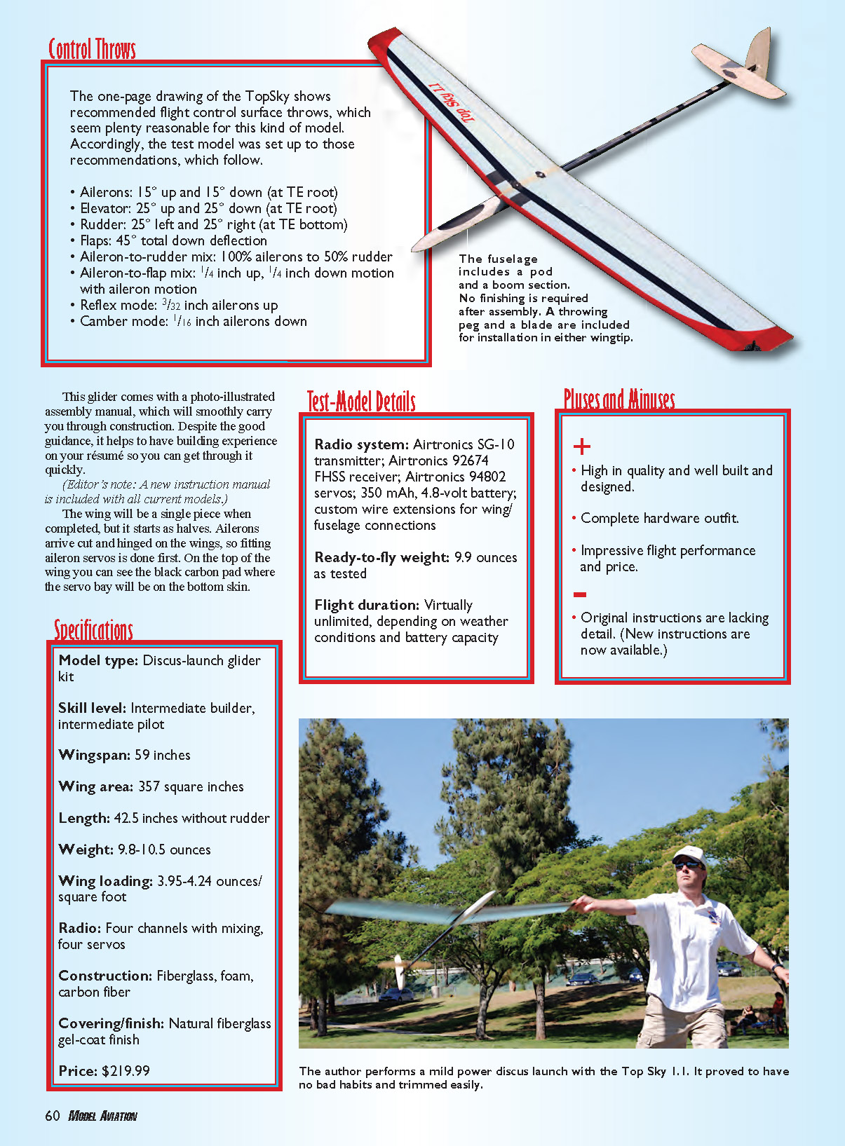
The one-page drawing included shows recommended flight control surface throws. The test model was set up to those recommendations:
- Ailerons: 15° up and 15° down (at trailing-edge root)
- Elevator: 25° up and 25° down (at trailing-edge root)
- Rudder: 25° left and 25° right (at rudder bottom)
- Flaps: 45° total down deflection
- Aileron-to-rudder mix: 100% ailerons to 50% rudder
- Aileron-to-flap mix: 1/4 inch up, 1/4 inch down motion with aileron motion
- Reflex mode: 3/32 inch ailerons up
- Camber mode: 1/16 inch ailerons down
Specifications
- Model type: Discus-launch glider kit
- Skill level: Intermediate builder, intermediate pilot
- Wingspan: 59 inches
- Wing area: 357 square inches
- Length: 42.5 inches without rudder
- Weight: 9.8–10.5 ounces
- Wing loading: 3.95–4.24 ounces/square foot
- Radio: Four channels with mixing, four servos
- Construction: Fiberglass, foam, carbon fiber
- Covering/finish: Natural fiberglass gel-coat finish
- Price: $219.99
Test-Model Details
- Radio system: Airtronics SG-10 transmitter; Airtronics 92674 FHSS receiver; Airtronics 94802 servos
- Battery: 350 mAh, 4.8-volt battery
- Wiring: Custom wire extensions for wing/fuselage connections
- Ready-to-fly weight: 9.9 ounces as tested
- Flight duration: Virtually unlimited, depending on weather conditions and battery capacity
Pluses and Minuses
- Pluses:
- High quality, well built and designed
- Complete hardware outfit
- Impressive flight performance and price
- Minuses:
- Original instructions lacked detail (new instructions are now available)
Launching and Flying
I made the first attempts in virtually perfect weather: sunny skies, mid-70s, and only a hint of wind. Standard practice for the first flight with a hand-launched glider is an overhand toss with just enough push to get it flying. This initial trim flight needed only two clicks of up-elevator to be perfect.
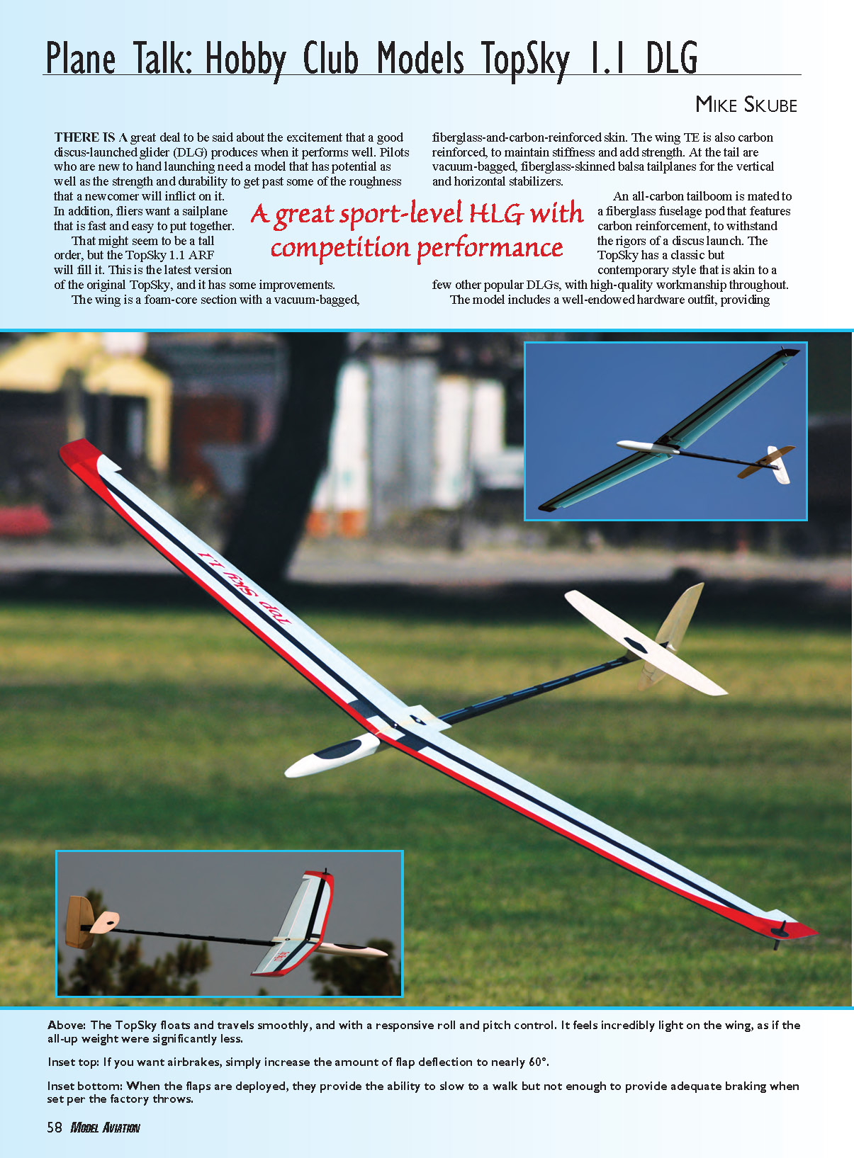
Low-energy discus tosses proved wonderful; the model exhibited no bad habits. Taking the TopSky through a few test tosses built a lot of confidence, so I gave full-weight throws. The sailplane assumed a mild climbing arc up to apogee, then pushed over prettily. Once on the wing, the TopSky floated smoothly with responsive roll and pitch control and felt lighter than its all-up weight.
Adding camber gives a noticeable lift advantage, and the TopSky responds quickly in roll. I noticed it suits an aggressive thermaling style: it will attack lift with some speed and circle tightly. That behavior is unusual for floater-type gliders but indicates the 1.1 will suit a wide variety of flying styles.
The first full-power toss topped out at approximately 125 feet and yielded about six minutes on the clock before a systems check. When a new sailplane thermals out on the first serious toss, it's a good sign. Subsequent throws confirmed the model's capability; specking out (flying for time) was no problem other than battery usage.
With factory flap settings, flaps provide enough slowing to be at a walk but not enough for strong braking. If you want airbrake-like performance, increase flap deflection to approximately 60°. Be ready to maintain forward momentum and steer with the rudder; ailerons will be less effective at slow speeds.
Wind penetration was good. The test model had a reflex mode set up and penetrated upwind well for only 9.9 ounces. During tests in a 6 mph wind, the TopSky handled nicely.
The fitted Airtronics servos were exceptionally quiet with solid performance and no digital buzz.
Considering current contest-level DLG prices, the TopSky is a bargain. Its build quality rivals many top-notch aircraft. Nothing radical was done to save weight in assembly or equipment, yet the 1.1 came in under the 10-ounce mark at 9.9 ounces ready to fly. Of the half-dozen pilots who flew this model, all agreed it handled and performed incredibly well, regardless of price.
Mated to Airtronics 94802 servos, the TopSky 1.1 offers entry-level DLG pricing with performance that can make you competitive. High quality and high performance have come down in cost — its name is the TopSky 1.1.
Mike Skube
Manufacturer/Distributor:
Top Soaring New Technology Co. LTD. / Hobby Club Box 6004 San Clemente, CA 92674 (949) 425-1362 www.hobbyclub.com www.topsoaring.com
Sources:
Airtronics (714) 964-0827 www.airtronics.net
Transcribed from original scans by AI. Minor OCR errors may remain.

