
Plane Talk: Multiplex Mentor Electric ARF
Eric Henderson
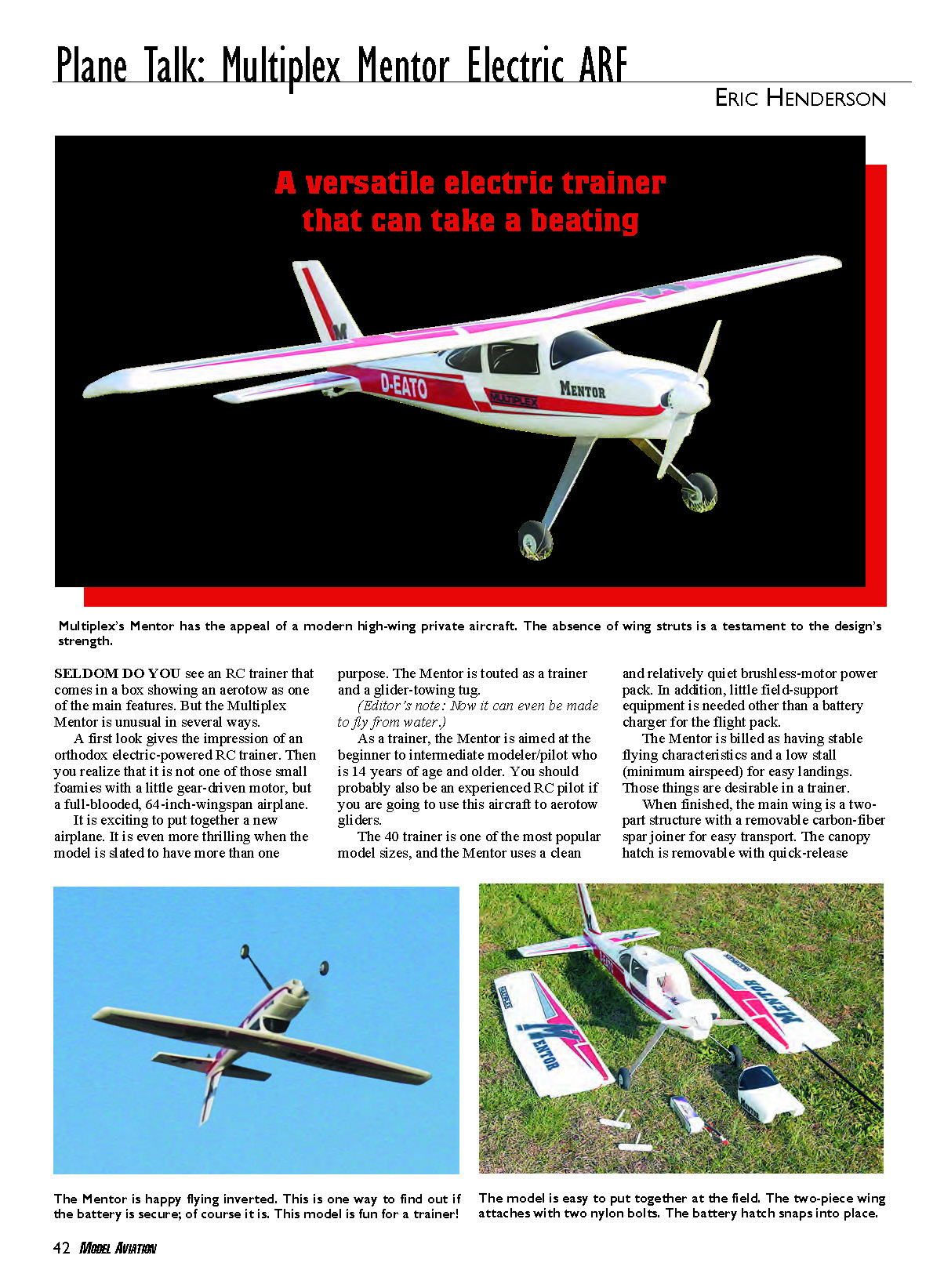
SELDOM DO YOU see an RC trainer that comes in a box showing an aerotow as one of the main features. The Multiplex Mentor is unusual in several ways.
A first look gives the impression of an orthodox electric-powered RC trainer. Then you realize that it is not one of those small foamies with a little gear-driven motor, but a full-blooded, 64-inch wingspan airplane.
It is exciting to put together a new airplane. It is even more thrilling when the model is slated to have more than one purpose. The Mentor is touted as a trainer and a glider-towing tug.
(Editor’s note: Now it can even be made to fly from water.)
As a trainer, the Mentor is aimed at the beginner to intermediate modeler/pilot who is 14 years of age and older. You should probably also be an experienced RC pilot if you are going to use this aircraft to aerotow gliders.
The .40 trainer is one of the most popular model sizes, and the Mentor uses a clean and relatively quiet brushless-motor power pack. In addition, little field-support equipment is needed other than a battery charger for the flight pack.
The Mentor is billed as having stable flying characteristics and a low stall (minimum airspeed) for easy landings. Those things are desirable in a trainer.
When finished, the main wing is a two-part structure with a removable carbon-fiber spar joiner for easy transport. The canopy hatch is removable with quick-release catches for an easy flight-battery swap.
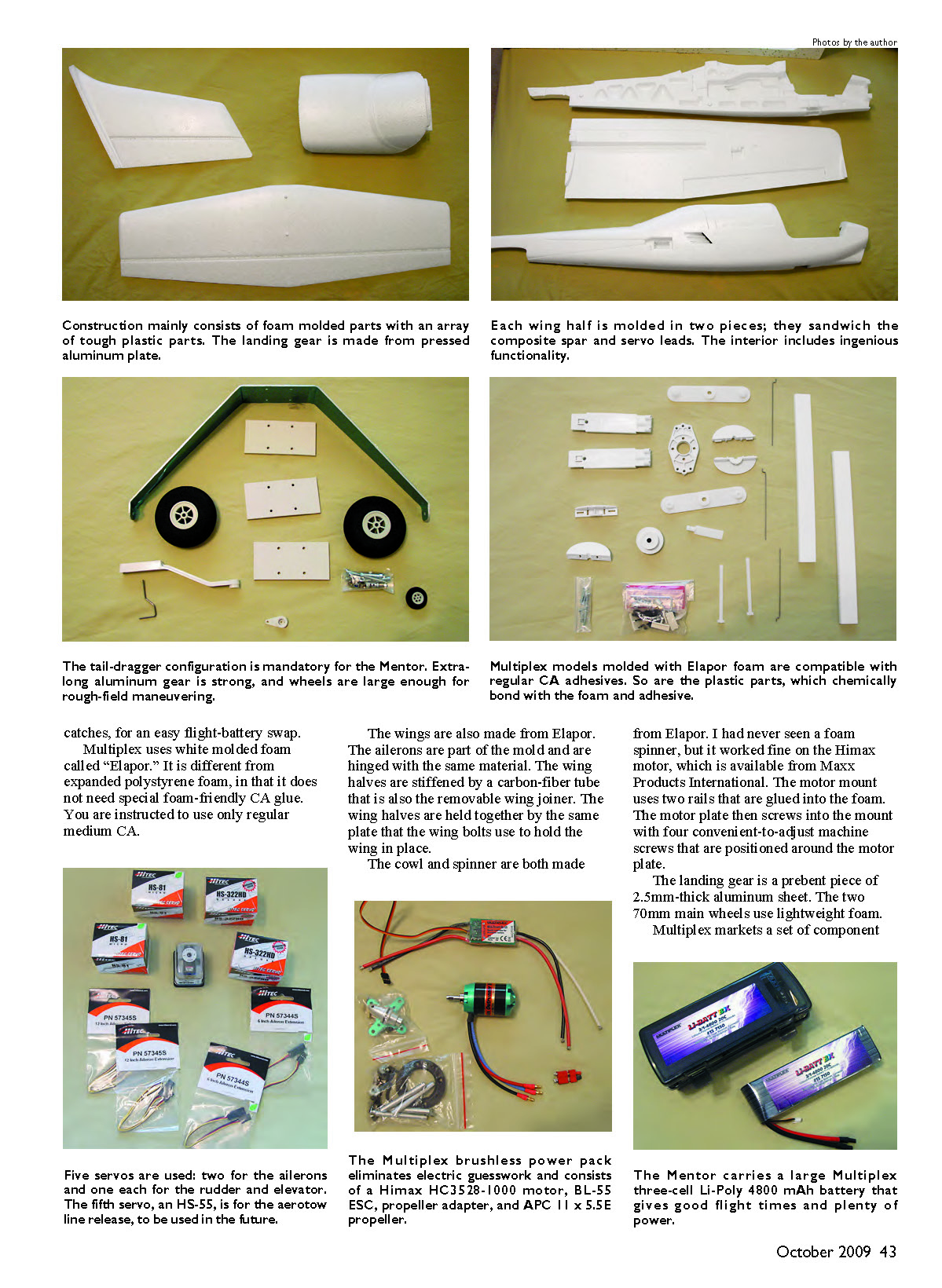
Five servos are used: two for the ailerons and one each for the rudder and elevator. The fifth servo, an HS-55, is for the aerotow line release, to be used in the future.
The Multiplex brushless power pack eliminates electric guesswork and consists of a Himax HC3528-1000 motor, BL-55 ESC, propeller adapter, and APC 11 x 5.5E propeller.
The Mentor carries a large Multiplex three-cell Li-Poly 4800 mAh battery that gives good flight times and plenty of power.
Construction mainly consists of molded foam parts with an array of tough plastic components. The landing gear is made from pressed aluminum plate. Each wing half is molded in two pieces; they sandwich the composite spar and the servo leads. The interior includes ingenious functionality.
Multiplex uses white molded foam called Elapor. It is different from expanded polystyrene foam in that it does not need special foam-friendly CA glue. You are instructed to use only regular medium CA.
The wings are also made from Elapor. The ailerons are part of the mold and are hinged with the same material. The wing halves are stiffened by a carbon-fiber tube that is also the removable wing joiner. The wing halves are held together by the same plate that the wing bolts use to hold the wing in place.
The cowl and spinner are both made from Elapor. I had never seen a foam spinner, but it worked fine on the Himax motor, which is available from Maxx Products International. The motor mount uses two rails that are glued into the foam. The motor plate then screws into the mount with four convenient-to-adjust machine screws that are positioned around the motor plate.
The landing gear is a prebent piece of 2.5 mm-thick aluminum sheet. The two 70 mm main wheels use lightweight foam.
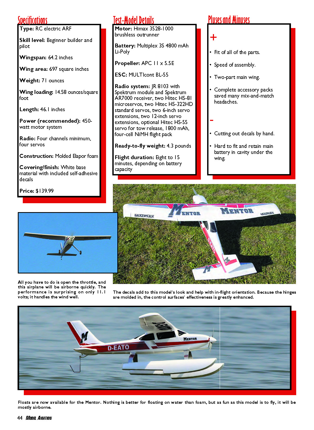
Floats are now available for the Mentor. Nothing is better for floating on water than foam, but as fun as this model is to fly, it will be mostly airborne.
Specifications
- Type: RC electric ARF
- Skill level: Beginner builder and pilot
- Wingspan: 64.2 inches
- Wing area: 697 square inches
- Weight: 71 ounces
- Wing loading: 14.58 ounces/square foot
- Length: 46.1 inches
- Power (recommended): 450-watt motor system
- Radio: Four channels minimum, four servos
- Construction: Molded Elapor foam
- Covering/finish: White base material with included self-adhesive decals
- Price: $139.99
Test-Model Details
- Motor: Himax 3528-1000 brushless outrunner
- Battery: Multiplex 3S 4800 mAh Li-Poly
- Propeller: APC 11 x 5.5E
- ESC: MULTIcont BL-55
- Radio system: JR 8103 with Spektrum module and Spektrum AR7000 receiver; two Hitec HS-81 microservos; two Hitec HS-322HD standard servos; two 6-inch servo extensions; two 12-inch servo extensions; optional Hitec HS-55 servo for tow release; 1800 mAh, four-cell NiMH flight pack
- Ready-to-fly weight: 4.3 pounds
- Flight duration: Eight to 15 minutes, depending on battery capacity
Pluses and Minuses
Pluses
- Fit of all of the parts
- Speed of assembly
- Two-part main wing
- Complete accessory packs saved many mix-and-match headaches
Minuses
- Cutting out decals by hand
- Hard to fit and retain main battery in cavity under the wing
Construction
The manual comprises a series of high-quality drawings in four languages. The builder should have some RC model-building knowledge.
It was helpful to study the pictures and then make construction lists. To make assembly even easier, I cut the four-language instructions and sorted them into their English components, then stapled each narrative next to the pictures and diagrams of the assembly.
Wing construction is made easier because it consists of two molded panels that end up as halves. Assembly begins with releasing the ailerons and flexing their premolded foam hinge lines. I had to add servo-extension leads to the aileron servos so that they would reach the wing center area.
Before gluing anything, you need to fit the servo arms to the Hitec HS-81 microservos. This means you must set the neutral positions with your radio for each arm on each servo. You can't do this once everything has been glued in place.
The foam cover forms a tube in the wing panel for the carbon-fiber wing-joiner tube. It also covers the servo lead/extension and holds the servo in place. Take care not to get CA in the tube area if you want to be able to easily slide in the carbon-fiber wing joiner. Also, do not put the carbon-fiber joiner in too soon in case any uncured CA decides to fix it there permanently!
The fuselage comes in halves that require a fair degree of preparation before they can be glued together. Fit the Hitec HS-322HD servos for the rudder and elevator into recesses on the outside of the molded fuselage halves and route their leads inside. Adhere the pushrod outer tubes into grooves in the outer skin of the foam parts.
I deviated slightly from the instructions with the wing bolts. I retapped the plates out to a 1/4 x 20 thread and used two nylon Allen-head bolts instead of the supplied metric threaded bolts. This choice was prompted by the better availability of standard hardware.
I installed a Hitec HS-55 servo that would operate a cable/towline release. This assembly was buried in one fuselage side. As with the ailerons, the servo arm needed to be set with the radio before it was glued in place—there would be no way to reach this servo later.
When you are ready to glue the fuselage halves together, lay everything out in advance. It is a good idea to enlist a friend to help with this task. I recruited my wife to hold the rear section together while I worked on the middle and front. I applied the CA quickly and liberally onto one side and gently squeezed the halves together.
The adhesive did not cure immediately, especially where there was a lot of it. Therefore, the halves needed to be held in several places for roughly five minutes. Some areas attached instantly, while others kept coming apart. Also, excess CA oozed out of the seams and had to be wiped off quickly. The process was a bit stressful, but we are still married. Next time we'll use more kicker.
To fit the stabilizer and fin, the wing needs to be bolted in place. It sat square in the wing seat and was a nice, tight fit. The Multiplex molds' accuracy was no more evident than when the wings lined up perfectly.
Gluing the tail feathers in place was simple and quick. Connecting the controls was easy because of the supplied adjustable swivel connectors at the horn end. Z-bends were used at all of the servo-arm ends.
A separate pushrod for the steerable tail wheel lets you set the rudder trim independent of the tail-wheel setting. The tail-wheel assembly and the main landing gear plate bolt together. The tail-wheel assembly glues in place. The mains are machine-screwed using additional landing gear plates that sandwich and add support to the preinstalled landing gear plate.
The motor was a good fit on the motor plate. The plate then fitted perfectly onto the previously installed motor mounts. You have to solder the connectors onto the battery and the ESC.
A BEC in a large ESC is rarely used alone to feed the receiver and servos because too much power can go to the motor and not enough left for the onboard radio system. A separate 1800 mAh NiMH receiver battery was used for this task. Be sure to disable the power feed to the receiver from the BEC.
The large 3S 4800 mAh pack is needed but remained under the wing to get the correct CG. The space was not a tight fit and there needed to be room for cooling air to flow past the battery pack.
I constructed a plywood-and-balsa frame that used Velcro straps to hold the pack in place. The Velcro allows the Li-Poly pack to be removed for charging and balancing.
Preparing the decals was tough; it took a little while to cut them by hand. However, they were easy to apply and could be lifted for alignment purposes as long as I had not rubbed them down. The result was worth the effort. The graphics not only improved the Mentor’s look and visibility, but they also covered the servos on the outside of the fuselage.
Motor and Battery
When you configure an electric model, it can be difficult to choose the proper motor, ESC, and battery. Multiplex has assembled a tried-and-true all-in-one (optional) power pack that takes away all the guesswork. It is optimized to give you the most out of your airplane. The configuration is designed to use a 3S 3200–4800 mAh Li-Poly battery pack.
The Mentor Power Pack includes a Himax 3528-1000 brushless outrunner motor with a Kv rating of 9,000. The pack also contains an APC 11 x 5.5E propeller, hub, and driver to match the motor’s shaft size.
Also included is a MULTIcont BL-55 brushless ESC with the following specifications: max continuous current 55 amps; voltage range 5–15 volts; designed for a 3S Li-Poly battery; and a BEC rated at 3 amps. The BEC was not used to power the five servos in our installation.
The motor installation was tested and measured. Initial results were that it drew 42 amps and 507 watts, showing 11.4 volts at full throttle. The motor turned the APC propeller at 4,950 rpm. These figures dropped off a bit after a few seconds.
Flight Report
An electric trainer this size still tends to be a new thing at the flying field. A few short taxi runs were all it took to check the steering, and we were ready.
I taxied the Mentor to the center of the runway and aimed it into the wind. The timer was set to go off after six minutes to give a good margin on the battery and allow for several landing attempts if required.
The takeoff run was straight and rapid. The big motor almost immediately delivered maximum torque; the tail came up quickly, and the aircraft was airborne in approximately 15 feet.
The climb was a bit steep at first, then it got even steeper. I put in roughly six clicks of down-elevator trim before entering the first turn. No elevator or rudder trim was required. The initial trim setting was all that was needed to achieve level and steady flight.
When I released the controls, the plane flew straight and level. When entering a turn, some bottom rudder was required to keep the fuselage nose level with the horizon.
Varying the throttle settings showed stable flight behavior down to a gentle stall. The Mentor would then drop the nose and recover quickly in airspeed in close to 4 feet of altitude.
I selected half throttle and made a landing circuit. Once the airplane was over the runway, leaving nearly two notches of throttle kept the propeller turning. The wings stayed level and the motor was brought back to 0 rpm approximately a foot above the grass. The model settled into a smooth landing 10 yards or so later.
The red, black, and silver decals proved to be necessary for in-flight orientation. The first flight was good and was quickly followed by more adventurous flights that included loops, rolls, and inverted flight. The airplane liked to skim in on the main wheels rather than be almost stalled down to a three-point landing.
The Mentor is a delight to fly and easy to guide around the sky. It loops majestically and gives a slight barrel roll with ailerons. Making aileron turns at cruising or high speed showed no adverse yaw. That is when the higher wing has more drag than the lower wing when a rolling action is created with the ailerons.
Aileron turn entries at slow speed liked a bit of bottom rudder to be added when initially going into the turn. This rudder input can be made manually or mixed in using a computer radio.
The Multiplex Mentor has the feel of a low-wing sport airplane—especially when you send more electrons to the brushless motor. Get some help putting one of these models together if you are an inexperienced builder, and it could appear early in your RC chronicles.
Even though the Mentor appears destined to be a trainer, it can be so much more. It flies as well as any 40- to 60-sized sport aircraft and has no nasty habits. It is a great airplane to fly for fun.
In addition, that aerotow-release servo is buried in the fuselage, just sitting there. You could use it to pull a ribbon or tow a banner, but it was designed to pull a glider. Now where did I put that Multiplex Cularis sailplane? (Editor’s note: See page 54 for that story.)
Eric Henderson [email protected]
Manufacturer/Distributor
Multiplex USA 12115 Paine St. Poway, CA 92064 (858) 748-6948 www.multiplexusa.com
Sources
- Maxx Products International — (847) 438-2233 — www.maxxprod.com
- Spektrum — (800) 338-4639 — www.spektrumrc.com
- JR — (800) 338-4639 — www.jrradios.com
- APC Propeller — (530) 661-0399 — www.apcprop.com
Other Published Reviews
- RC Model World: October 2008
- Model Airplane News: January 2009
- Quiet and Electric Flight International: January 2009
Transcribed from original scans by AI. Minor OCR errors may remain.

