
Plane Talk: Pacific Aeromodel Gee Bee Model Y
Nick Schriefer
A 1/4-scale ARF version of the sport aircraft that preceded the famous Doolittle-piloted racer
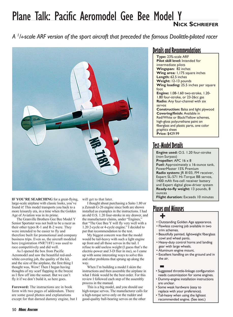
If you're searching for a great-flying, large-scale airplane with classic looks, you've found it! This model transports you back to a more leisurely era, when the Golden Age of Aviation was in its prime.
The Granville Brothers Gee Bee Model Y Senior Sportster was not built to be a racer like their R-1 and R-2 types. It was intended to be easier to fly and therefore built for promotional and company business trips. Even so, the aircraft modeled here (registration NR718Y) was used to race competitively and did well.
As I opened the box from Pacific Aeromodel and saw the beautiful red-and-white covering job, the quality of the kit, and the size of the airplane, the first thing I thought was, “Wow!” Then I began having thoughts of my scarf flapping in the breeze as I flew off into the sunset. But we can't fly it if we don't build it, so here goes.
Foreword
The instructions come in book form with two pages of addendum. There are some good photos and explanations — except for that darned dummy engine, but more on that later. I considered a Saito 1.80 or a Zenoah G-26 because both are shown installed as examples in the manual. I had an old O.S. 1.20 four-stroke in my drawer, and the manufacturer claims under "Engines" that "The Gee Bee Y will fly very well with a .120 2-cycle or 4-cycle engine." I decided to put that recommendation to the test.
My biggest concern was that the model would be tail-heavy with such a light engine up front and all those servos in the tail. I refuse to add useless weight (I guess that's the electric-power and 3-D flier in me), so I came up with some ways to solve this and other problems that sprang up along the way.
When I'm building a model I skim the instructions and then assemble the airplane in what I think is the best order. For this review I followed each step of the assembly process in the manual. This is a big model, and you should use high-torque servos. The manufacturer calls for a high-torque servo only on the rudder and good-quality ball-bearing servos on the other control surfaces. If you don't have the necessary servos, buy good ball-bearing servos that have a high torque rating; it's money well spent.
The instructions also call for three 12-inch and one 18-inch servo extensions and two Y-connectors. I used four 18-inch extensions, which allowed me to plug my ailerons directly into the receiver without the need for short pigtails. Then I programmed the transmitter for split elevators and activated flaperon control for the ailerons. A servo reverser was unnecessary because of the servo placement for the elevator. If you don't have a computer radio, Y-connectors will work fine to link these servos.
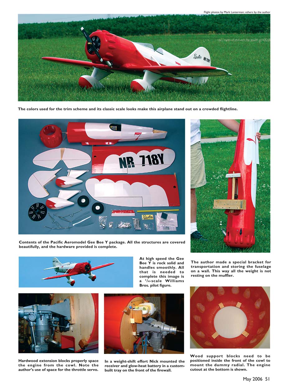
The wing is made from two pieces joined with an aluminum tube and alignment pin. It is held together and to the fuselage with a plywood tab and two hefty bolts. This assembly feature makes transportation and storage easy.
Assembly
Follow the manual until you reach the section titled "Assembling the Wings." It's much easier to install the control horns before this point. Follow the addendum and use the included bolt-style horns. Install them through the hard points in the ailerons.
I thought the pushrods were a bit small for this size of model, but as short as they are they should not present a problem if you fly in a scale-like manner.
Make sure you follow the addendum for the axle pads and wheel-pant installation. The instructions tell you to cut through the bottom flange at the slot so you can get the gear struts inside. The review model came with the cuts already in place, but this allowed the flanges to warp.
I tried to straighten them and cracked the paint on one of the gear covers in the process. I corrected the problem by using a heat gun on the inside to soften the fiberglass just enough to straighten it. This worked great and did not harm the paint in any way. With the gear assembly finished, the wing was done.
At this point you must decide what engine you will use. Don't forget to change the fuel lines if you go with a gas engine — the tubing supplied is silicone and is incompatible with gasoline.
Since the O.S. .120 is shorter than roughly .150-size engines, it did not stick out far enough to meet the thrust-washer setting of 6-1/2 inches from the firewall. I used hardwood blocks and spaced the engine mount away from the firewall almost 3/4 inch farther forward.
Because mounting the throttle servo in the recommended place would have created linkage-angle complications, I mounted the throttle servo on the firewall between the new hardwood standoffs. This solved the linkage setup and added more weight to the front of the airplane.
To ensure usable weight was moved forward, I made a plywood battery box and secured it to the front of the firewall. I almost went with a pull-pull system for the rudder, which would have reduced tail weight even more.
The instructions clearly state that if you leave the dummy radial engine off, you could have overheating problems. Its purpose is to direct cool air over the real engine.
The original instructions and the addendum describe two different methods of attaching the dummy engine. Perhaps an illustration would have helped; it was unclear to me exactly where the mounting points were supposed to be.
I placed the cowl nose-down and laid the included balsa blocks inside the cowl with the flats facing up. I spaced them so that when the dummy engine is placed inside, the cutout is at the bottom (where the real engine would be) and the cylinder-head parts of the dummy engine rest on the flats of the four balsa mounting points. With each cylinder lined up between two respective cowl bumps, I glued everything together.
I did not trust the idle on the old four-stroke mounted in the inverted position, so I installed an onboard glow system and mounted the battery for it above the receiver battery on the firewall. To establish a perfect CG, all I needed was a small brass spinner to finish the front end.
To fuel the aircraft I installed a Robart Super Fueler (part 204) on the cowling between the fuel tank and carburetor. It looks like a smaller cowl bump and blends in as if it were made for this application.
The rest of the instructions were straightforward. I had to replace two of the clevises while hooking up the elevator pushrods (they broke apart when opened). Luckily I had some 2mm clevises left over from another project.
The pushrods came made to length, and even though I felt they were a bit light for a .120-size airplane I used them for the review and had no problems.
After setting up the radio I installed the windshield. I followed the instructions but reinforced the screw holes inside the fuselage with scrap plywood for added security. At this point it was time for the most important step: recheck everything.
Flight Performance
When I arrived at the field to meet the photographer I had my reservations about the weather. It was foggy and cloudy, with a fairly steady 15 mph wind that was more or less down the runway. I thought to myself, "The show must go on."
Flying in wind doesn't bother me, but I knew I would not have any excess power with only a .120 four-stroke up front; maiden flights are always unnerving. I put the Gee Bee together, checked the battery, and fueled it up. After a range check we were ready to go.
The model taxied well through the grass out to the awaiting runway. The wind was blowing across the runway at roughly a 45° angle and still at 15-plus mph. I reminded myself of the saying, "Sometimes they fly; sometimes they die," and gave it a little rudder into the wind and hit the throttle.
To my surprise and delight the Gee Bee went straight down the runway and lifted off with authority. At the top of its climb it was obvious that the manufacturer had not exaggerated about this airplane flying very well with only a .120. With this engine it does a great tailslide at full throttle when it just can't climb any higher.
I climbed the model to a nice altitude, performed a Split S, and came back over the runway. Trim was almost dead-on, with only a couple blips of down-elevator needed. After several circuits over the field I brought the airplane down for some photo passes and fun. Tracking was straight, and this big Gee Bee was a pleasure to fly.
Inverted flight and knife-edge down on the deck are not scale maneuvers for this aircraft, but they sure are fun. After buzzing the soybeans inverted and dipping a wingtip as close as I could get in the beans, I took the model back up for some stall tests. All it did was drop the nose and mush forward.
I found no bad tendencies other than some roll coupling while trying to perform knife-edge flight — a maneuver that is always tough with an airplane that is not designed to fly that way and that has a fair amount of dihedral.
All normal scale maneuvers with this aircraft were enjoyable, including spins. For flat spins you have to set up some high rates. Landings are completely uneventful: set up and fly this model back to the runway before powering all the way back to idle.
I liked flying this airplane so much that after the photo shoot the photographer and I each flew through two more tanks of fuel. By that time the clouds had departed and we shot a few more pictures to show off how great this classic old airplane looks in the air. I think that says it all.
MA
Nick Schriefer [email protected]
Manufacturer
- Pacific Aeromodel Mfg. Inc.
- 12368 Valley Blvd. #109
- El Monte, CA 91732
- (800) 780-0100
- www.pacaeromodel.com
Suppliers of Additional Items
- Robart Mfg. Inc.
- Box 1247
- St. Charles, IL 60174
- (630) 584-7616
- www.robart.com
- JR and Expert products:
- Horizon Hobby Inc.
- 4105 Fieldstone Rd.
- Champaign, IL 61822
- (800) 338-4639
- www.horizonhobby.com
Transcribed from original scans by AI. Minor OCR errors may remain.

