
Plane Talk: Quique’s Aircraft Company 86" Yak 54
BY ANDREW JESKY
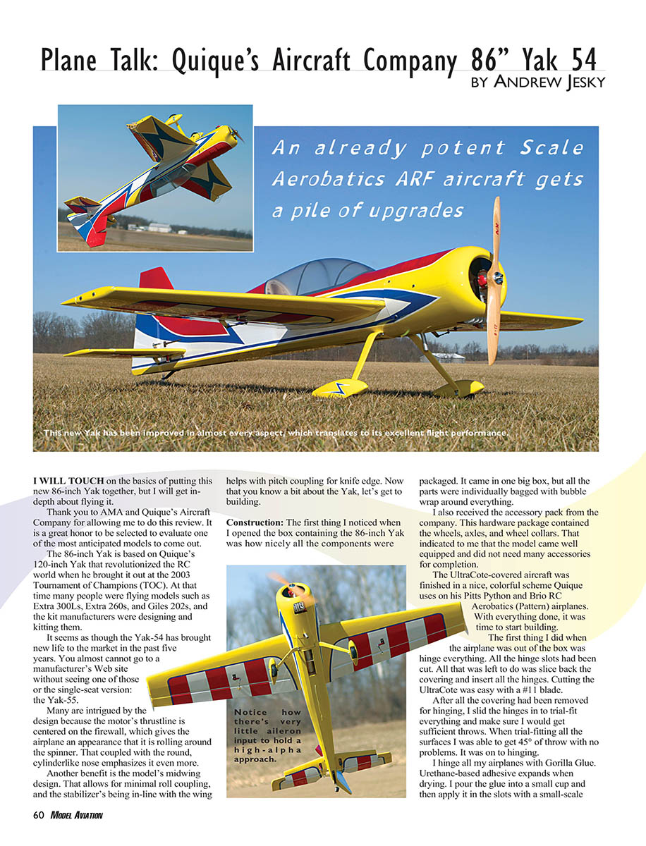
An already potent Scale Aerobatics ARF aircraft gets a pile of upgrades
I will touch on the basics of putting this new 86-inch Yak together, but I will get in-depth about flying it.
Thank you to AMA and Quique’s Aircraft Company for allowing me to do this review. It is a great honor to be selected to evaluate one of the most anticipated models to come out.
The 86-inch Yak is based on Quique’s 120-inch Yak that revolutionized the RC world when he brought it out at the 2003 Tournament of Champions (TOC). At that time many people were flying models such as Extra 300Ls, Extra 260s, and Giles 202s, and the kit manufacturers were designing and kitting them.
It seems the Yak-54 has brought new life to the market in the past five years. You almost cannot go to a manufacturer’s website without seeing one of these or the single-seat version, the Yak-55.
Many are intrigued by the design because the motor’s thrustline is centered on the firewall, which gives the airplane an appearance that it is rolling around the spinner. That, coupled with the round, cylinder-like nose, emphasizes the effect. Another benefit is the model’s midwing design, which allows for minimal roll coupling; the stabilizer’s being in-line with the wing helps with pitch coupling for knife edge. Now that you know a bit about the Yak, let’s get to building.
Construction
Packing and initial inspection
The first thing I noticed when I opened the box containing the 86-inch Yak was how nicely all the components were packaged. It came in one big box, but all the parts were individually bagged with bubble wrap around everything. I also received the accessory pack from the company, which contained the wheels, axles, and wheel collars. That indicated the model came well equipped and did not need many additional accessories for completion.
The UltraCote-covered aircraft was finished in a nice, colorful scheme Quique uses on his Pitts, Python, and Brio RC Aerobatics (Pattern) airplanes. With everything done, it was time to start building.
Hinging and covering
The hinge slots had been cut at the factory. I sliced back the covering and inserted all the hinges—cutting the UltraCote was easy with a #11 blade. After trial-fitting the hinges I was able to get 45° of throw with no problems.
I hinge all my airplanes with Gorilla Glue. This urethane-based adhesive expands when drying. I pour the glue into a small cup and apply it in the slots with a small-scale ruler. Make sure not to use too much glue; it will expand back into the hinge and cause friction. If you have never used the glue, practice on a scrap block of wood to find the right amount. With Gorilla Glue all the surfaces can be hinged at once; it takes roughly 12 hours to dry. I left the model to sit out for approximately two days to let any humidity escape from the wood.
When I came back I saw some wrinkles in the covering, so I went over it with a heat gun and iron following the instructions to shrink the covering back down.
Landing gear and tail wheel
After shrinking the covering I installed the landing gear and tail wheel so the airplane would sit on its own base while I worked. The landing gear installed easily with predrilled holes; I ran the screws in from the top and put lock nuts on the bottom. The tail wheel mounted to blind nuts in the tail. If you prefer, leave the wheels off the gear while working to prevent the model from rolling.
Engine selection and installation
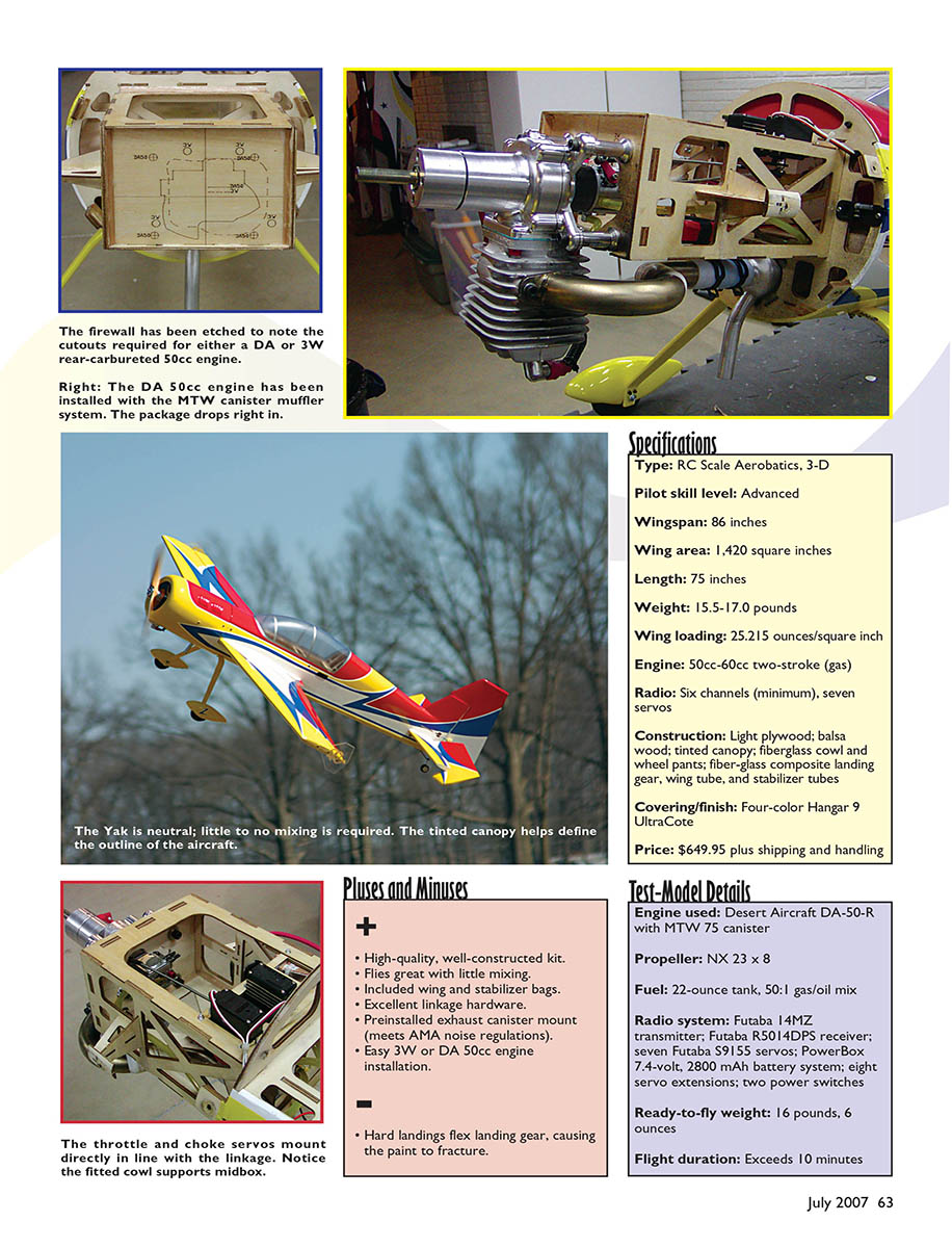
A nice feature of this model is that the firewall was already marked for both the 3W-50 and the DA-50 engines. I planned to use a DA-50 with an MTW canister for quieter operation. The 3W and DA engines use rear-induction carburetors, and there were laser-marked lines on the firewall indicating where to cut depending on the engine chosen.
After drilling the 1/4-20 holes in the firewall, I cut the firewall opening with a Dremel and a cutting wheel. When I got close to the lines I switched to a sanding drum to clean up the cuts and reach the corners. I bolted the engine to the firewall to verify alignment before mounting the header and canister.
I cut 8mm off the header to get the correct length for the Yak, then slid the header onto the can with a Teflon coupler. The can mounts were already in the airplane, so I slid the MTW can onto the mount and cut the covering back so the can could vent heat out the bottom of the model.
For final installation I used Loctite on the mounting screws and sealed the header/canister connection with red RTV silicone. The model was set up for a choke servo because the rear-induction carburetor choke is hard to access. The Yak came with a servo plate glued to the engine box when the servos were installed.
Setting up the throttle and choke was straightforward with 4-40 rods and ball links. Make sure travel adjustment/ATV is as equal as possible on the high and low ends for best servo resolution. On this model I used zero subtrim and ATV set to 120 on both low and high.
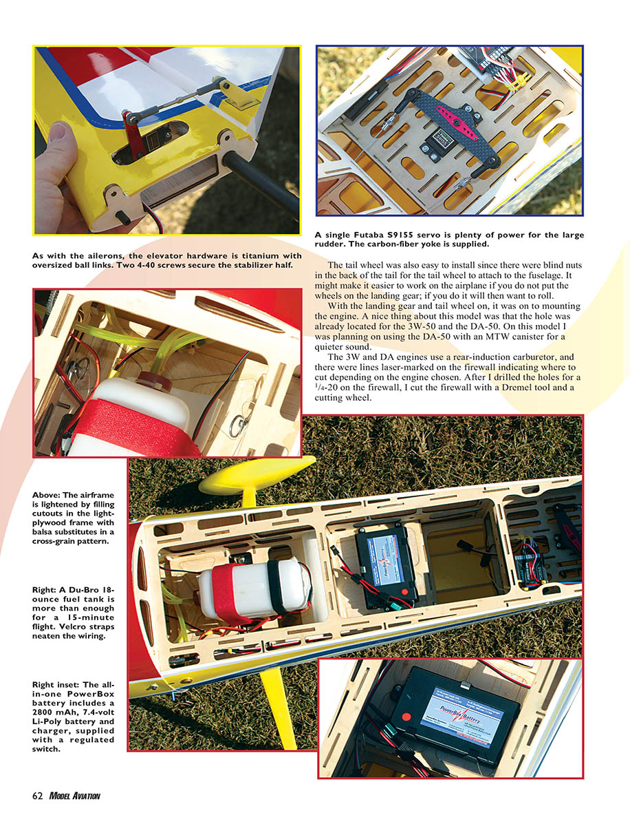
After that I installed the fuel tank, ignition, and ignition battery—these components were quick to mount.
Cowl
Cutting the cowl openings required careful measurements so I would not have to cut a huge hole. I rough-cut the openings with a cutting wheel and cleaned them with a sanding drum. The instructions gave dimensions for spacing and drilling; once all bolts were drilled and blind nuts mounted, the cowl was ready for final installation.
A tip from Larry Markey: use silicone under the cowl where it meets the fuselage to create a bond and prevent the screw holes from becoming oblong if screws loosen.
Wing servos, control horns, and sealing
Installing the servos in the wing was straightforward. The servo pockets were pre-cut; I used Futaba 9155s (195 oz-in torque at .13 sec). The control horns are G10 fiberglass pieces made of two side pieces and a baseplate. I glued the control horns in with Gorilla Glue and waited overnight to dry.
I installed Futaba 1.5-inch aluminum servo horns and the kit’s titanium turnbuckle control rods and ball links. It took roughly 10 minutes per wing to hook up the control rods and make them functional. After both wings were done I sealed the hinge gaps.
Larry Markey showed me an excellent trick for sealing hinge lines: use clear, flexible 3M Blenderm tape (commonly used for foams). It makes sealing simple and reliable.
The wing is held on by two body pins commonly used in RC cars. These are secured with a washer and rubber O-ring. It’s critical to get the pin length right; too much exposes slop in the wing saddle, too little prevents secure attachment. I followed the instructions and aligned the pins correctly.
I mixed 30-minute epoxy with microballoons and made a fillet around the pins where they attached to the ribs. Before gluing I roughened the aluminum rods so the epoxy would adhere.
Side force generators (SFGs)
I located the holes in the wingtips for the side force generators, opened them up, and bolted the SFGs on—the blind nuts were already installed.
Stabilizer and antirotation pin
I installed the stabilizer servos into the stabilizer root with only the servo arm protruding from the bottom, cutting the covering to allow for the control horn. I again used Futaba 9155 servos and 1.5-inch control arms. The control horn was installed and sealed just like the wing. The antirotation pin is a 4mm carbon rod glued into the stabilizer; I rounded it so it slides into the fuselage more easily.
Fuselage, rudder, and pull-pull setup
I cut back covering where needed: wing saddle, stabilizer cutouts, and rudder-cable exits. The wing saddle is 2mm balsa; I rolled the covering over the saddle to keep it secure, leaving about 3/8" around the edge and making a couple of relief cuts to blend the covering.
For the pull-pull rudder setup I installed a double-arm control horn (same style as the wing horns) using Gorilla Glue and made sure the ball-link holes were in-line and exactly 90° to the hinge line—incorrect geometry will cause slack in the pull-pull wires. I installed the rudder servo (Futaba 9155) in the fuselage.
The kit included a carbon-fiber rudder horn with a built-in 7° offset for correct geometry. I drilled and tapped it to 4-40 and mounted it to a Futaba 20mm double arm. I finished the rudder installation with the supplied pull-pull cables and added a plastic sleeve over one cable where they crossed to prevent chafing.
Electronics, battery, and receiver
The fuselage had a standard switch cutout, but I installed a PowerBox Digi-Switch instead. It has a built-in regulator and fail-safe, which will turn on in case of a fault rather than shut off unexpectedly.
I used a PowerBox 2800 mAh LiPo main battery pack. These batteries have performed well in my 40% airplanes and hold voltage better than many other Li-ion styles. The battery mounts in a strong holder with servo screws and grommets. The pack has a built-in charger and only requires a 12-volt power supply for charging.
I used a Futaba G3 receiver mounted per the manual. I put a piece of masking tape on the bottom of the receiver and glued it to protective foam for vibration damping. I ran the necessary extensions and mounted the wheels and wheel pants—the accessory pack saved time by including wheels, axles, and wheel collars. The wheel pants fasten with two 4-40 screws into wood that was pre-glued to the pants; be sure the wheel pants are aligned parallel.
Prop, spinner, balance, and weight
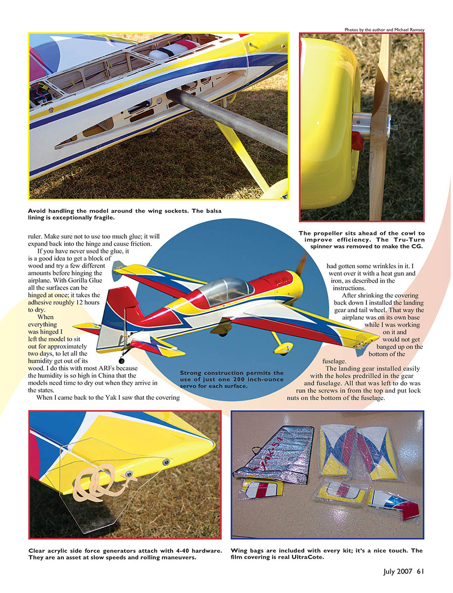
I installed an NX 23 x 8 wood propeller for break-in and a 4-inch P-51 Tru-Turn spinner cut for this model. After balancing, the Yak came out slightly nose-heavy; I flew initial test flights without the spinner to refine balance. The model’s weight was 16 lb 6 oz—a terrific weight for a DA-50-powered airplane. I set up the model on my 14MZ transmitter and followed the recommended initial-flight settings.
The Fun Begins (Flight testing and performance)
I met MA Associate Editor Michael Ramsey at the Celina, Ohio, flying field for test flights. A few nights earlier I had run the engine for a bit of break-in. It started on roughly the fourth flip and ran well. The 23 x 8 prop was turning 6,700 rpm on the ground while running rich for break-in—leaning will gain several hundred more rpm.
I did a range check and installed the SFGs for the first flight. Takeoff was straightforward; the Yak lifted off with about three clicks of up elevator, confirming its slightly nose-heavy setup. I made a few trim passes, then ran through roll and loop combinations to verify straightness.
I tested snap rolls, some 3-D, and landed after roughly five minutes to confirm bolt security. Everything checked out.
In knife edge the airplane required about 5° of knife-edge mixing to track straight down the runway; I expect this will change when I move the CG slightly aft. With knife edge mixed out I tested the SFGs: rolling circles and rolling loops showed the SFGs reduced the rudder required to pull around corners when rudder was applied.
Knife-edge loops performed well but showed some mixing at the bottom of the loop—this would be best corrected with curve mixing rather than a straight-line mix. The Yak’s RC Aerobatics capabilities were excellent, and it handled all 3-D maneuvers I tried.
Although the ailerons looked small compared to the wing, on high rates the roll rate was rapid—even with the SFGs installed. Flat spins were very flat and easy to recover from, even with the CG a bit forward. Knife-edge spins entered readily, which was impressive.
I tested waterfalls (tight vertical maneuvers); the airplane turns tightly but requires prompt rudder input or it will dish out. Hovering was stable—during a Harrier I brought it down the runway into the wind and tugged slightly more power to enter a torque roll. The Yak was stable in torque roll and had plenty of control authority to recover from hovering; add corrective control and a bit of power and it will respond cleanly.
Power with the DA-50 is impressive—the pullout was like a rocket even while running rich. Rolling harriers were excellent; when aileron throw is set properly, the model appears to spin around the cowl, creating a striking visual.
This airplane is a winner: built very nicely and flying fantastically. If you are looking for a new 50cc airplane, consider Quique’s Yak. It flies like a much bigger model and could be used in IMAC up to Advanced-class Aerobatics. It will be my new Freestyle practice airplane because it can be thrown around without problems.
The only issue I found was the composite landing gear’s finish. While performing a Harrier landing the paint on the landing gear cracked off. The gear itself did not crack—only the paint. Quique’s Aircraft Co. is aware of the problem and thinks the primer surface might not have been cleaned properly or that the primer might need a plasticizer for more flexibility. The landing gear was not designed specifically for Harrier landings.
Andrew Jesky [email protected]
Manufacturer/Distributor
- Quique's Aircraft Company
- 3410 Saint Paris Pike
- Springfield, OH 45504
- (937) 629-0339
- www.somenzini.com
Sources
- Radio equipment: Futaba — www.futaba-rc.com
- Battery: PowerBox Systems — www.powerbox-systems.com
- Engine, muffler: Desert Aircraft — www.desertaircraft.com
- Hardware accessories: Du-Bro — www.dubro.com
- Spinner: Tru-Turn — www.tru-turn.com
Transcribed from original scans by AI. Minor OCR errors may remain.

