
Plane Talk: Seagull Models Dual Ace 46 Twin ARF
BY JIM FELDMANN
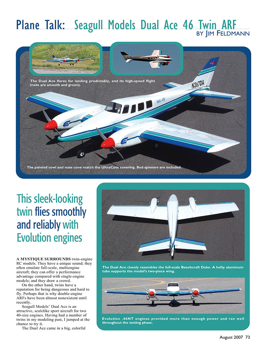
This sleek-looking twin flies smoothly and reliably with Evolution engines
A mystique surrounds twin-engine RC models. They have a unique sound, often emulate full-scale multiengine aircraft, can offer a performance advantage compared with single-engine models, and they draw a crowd.
On the other hand, twins have a reputation for being dangerous and hard to fly. Perhaps that is why double-engine ARFs have been almost nonexistent until recently. Seagull Models' Dual Ace is an attractive, scalelike sport aircraft for two 40-size engines. Having had a number of twins in my modeling past, I jumped at the chance to try it.
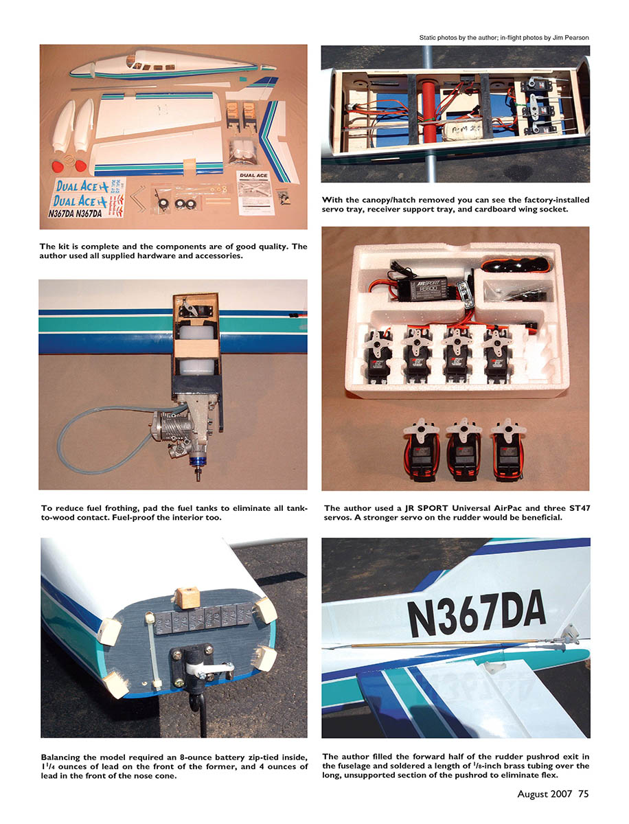
The Dual Ace came in a big, colorful box, and the packaging seemed adequate to prevent shipping damage. The individual parts appeared well built and sturdy. The covering (UltraCote) on my model was well done, with minimal wrinkles, but seemed loose in some areas.
The fiberglass nose cone, tail cone, and nacelle covers were thicker than most, and the paint was generally smooth and a good match to the covering. The engine nacelle frames were factory assembled and needed only to be glued into the wings.
The two-piece wing used an aluminum tube joiner, and the fuselage had a large hatch to provide access to the radio equipment and wing-attachment bolts. These advanced design features make assembly, transportation, and maintenance easier. The hardware and accessories seemed adequate to the task, but I felt some personal hardware changes were necessary.
Specifications
- Type: Sport aerobatic ARF
- Pilot skill level: Intermediate/advanced
- Wingspan: 70 inches
- Wing area: 880 square inches (actual)
- Length: 67 inches overall (actual)
- Weight: 11 pounds (typical)
- Wing loading: 29.3 ounces/square foot
- Engine: Two .40–.46 two-strokes
- Radio system: Four channels minimum, seven servos
- Construction: Built-up balsa and plywood; fiberglass nose cone, tail cone, nacelle covers; aluminum wing tube; plastic canopy; wire landing gear
- Covering/finish: UltraCote covering; fuelproof paint on fiberglass parts
- Street price: $189.99+
Test-Model Details
- Engines used: Evolution .46NT
- Propellers: APC 11 x 5
- Fuel: Morgan Fuels 15% Cool Power (tank capacity)
- Radio system: Futaba 8UA transmitter; FP129DP receiver; seven JR ST47 servos; 1200 mAh, 4.8-volt battery; four 12-inch extensions; four 9-inch extensions
- Ready-to-fly weight: 11 pounds, 3 ounces
- Flight duration: 10–15 minutes plus with normal throttle discipline
Pluses and Minuses
- Easy to fly, hard to stall — great qualities for a twin.
- Attracts attention on the ground and in the air.
- Fast and reasonably aerobatic.
- Two-piece wing.
- Hard-mounted fuel tanks cause fuel to foam.
- Fiberglass nacelle covers do not fit well and are difficult to install.
- Rudder pushrod flexes when turning right.
- Assembly manual contains numerous minor errors and omissions.
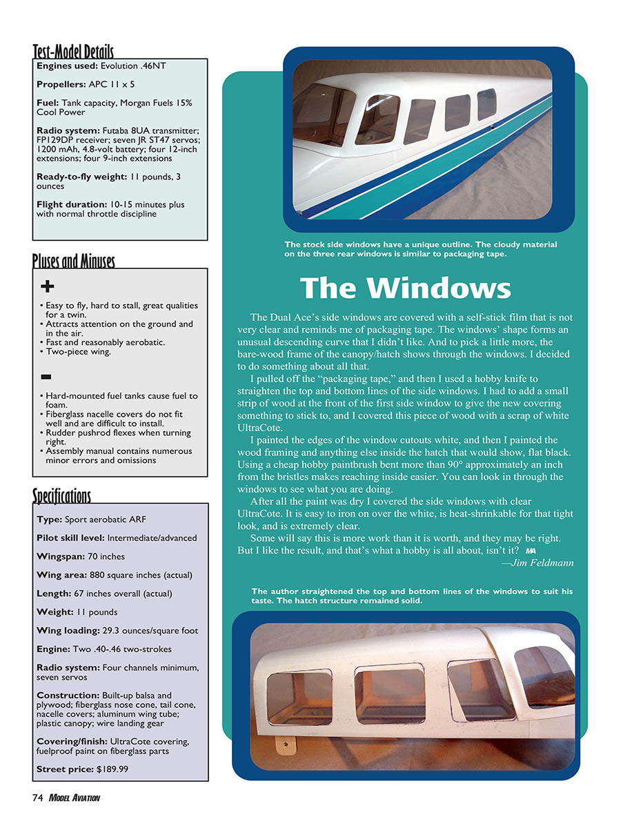
The Windows
The Dual Ace's side windows are covered with a self-stick film that is not very clear and reminded me of packaging tape. The windows' shape forms an unusual descending curve that I didn't like. The bare-wood frame of the canopy/hatch shows through the windows.
I pulled off the "packaging tape," then used a hobby knife to straighten the top and bottom lines of the side windows. I added a small strip of wood at the front of the first side window to give the new covering something to stick to, and covered this piece with a scrap of white UltraCote. I painted the edges of the window cutouts white, and painted the wood framing and anything else inside the hatch that would show, flat black. Using a cheap hobby paintbrush bent more than 90° about an inch from the bristles makes reaching inside easier; you can look in through the windows to see what you are doing.
After all the paint was dry I covered the side windows with clear UltraCote. It is easy to iron on over the white, is heat-shrinkable for that tight look, and is extremely clear. Some will say this is more work than it is worth, and they may be right. But I like the result, and that's what a hobby is all about, isn't it?
— Jim Feldmann
Getting It Together
The photo-illustrated, step-by-step assembly manual is adequate for the experienced ARF assembler. Some pictures don't match the text, and some of the text seems borrowed from elsewhere. Still, if you have assembled a few ARFs you should have no trouble getting this one together.
Assembly starts with the wings and proceeds like a typical ARF. Cyanoacrylate hinges are installed, and aileron servos are mounted inside the wing servo bay covers. Extra-long servo arms are needed for the aileron servos. The control horns are different from what we usually see, but they are heavy-duty and easy to install.
The included metal clevises should be more than adequate, but I recommend adding a fuel-tubing "safety band" to help keep them closed. I found one warped aileron and one warped elevator, but twisting them and then applying generous amounts of heat from my covering iron straightened them fairly well.
Installing the plywood nacelle frames, throttle servos, tanks, and engines is no more difficult than installing the engine in a single-engine model; you just have to do it twice. The second time is easier because you have already done it once.
I started by epoxying the nacelle frames into their sockets in the front of the wings. Before I did that I thought about keeping those engines running.
Twin engines make much more vibration than a single power plant. Vibration can cause the fuel in the tank to froth, and when that happens the engine will draw air bubbles instead of fuel, causing it to lean out and probably stop running. The fuel tanks should be protected from vibration. Unfortunately the Dual Ace's fuel tanks are hard mounted. To make room for padding I removed the U-shaped tank supports from inside the nacelle frames.
The outside of the nacelle frames was painted with a gray fuel-proofer, but since the fiberglass nacelle covers don't touch the firewall the entire nacelle and everything in it will be exposed to fuel residue. After gluing the nacelle frames into the wings I coated them, inside and out, with finish-cure epoxy. This adds to the structure's strength and stiffness and provides protection from fuel.
Installing and padding the tank will have to wait until after the throttle pushrod is in place. Skipping ahead in the manual, I installed the engines.
The top edge of the engine-mount beams should be within 1/16 inch of the top of the firewall. Then add the throttle servos and hook up the pushrods. Creative bending is needed to keep the pushrod up against the side of the nacelle, but you can bend the second one to match the first and that makes it slightly easier.
I hooked up the servos with a "Y" adapter and worked the throttle to make sure both engines' carburetor barrels opened at the same time. This is critical if you plan to use a "Y" to drive the servos, but it gives the best starting point even if you plan on using separate channels.
The included fuel tanks use plastic fuel tubing instead of the usual brass or aluminum. Bend these to shape using heat, but be careful; too much heat will melt them. The included silicone fuel tubing is too short and too stiff to allow the clunk to reach the bottom of the tank. I had to search for some softer fuel tubing for the clunk line.
The choice of a two- or three-line setup is yours. (The manual is no help here.) To add the third line you need to drill through the molded nipple at the top of the tank. Drill straight or you will break out the side of the nipple and ruin the tank.
After I set up the tanks I glued 1/4-inch foam rubber to the bottom of the nacelles and between the nacelles. I used two pieces of foam on the nacelles—one above and one below the throttle pushrod. A couple layers of wing-saddle tape stuck to the top and back of the tank keeps it from touching wood there. A padded sheet of light plywood glued across the top of the tank between the nacelle sides keeps everything in place. To prevent the fuel from sloshing the tank must not touch anything hard—anywhere.
The Evolution engines I'm using allow the needle valve to be relocated from the backplate to the carburetor. I did this because it makes tuning the engine easier and more precise, and it greatly simplifies installing a fuel filter. Again, I'm doing everything possible to make the engines more reliable.
Installing the fiberglass nacelle covers is the most frustrating part of assembling the Dual Ace. They just don't fit very well. The procedure outlined in the manual is probably the best way to do it, but the first step is fairly important and seems to be left out of the manual. It should instruct the builder to make a mark on the top and bottom of each wing, 8 inches from the root end of the wing and 3-7/8 inches from the aileron leading edge. Use those marks to align the rear end of the nacelle covers.
Two of the covers are marked "1" inside and two are marked "2." It appears that 1s go together to make a set and the 2s the other set. There doesn't seem to be a clear left/right difference; use them where they come closest to fitting.
Take your time and double-check everything before you drill the mounting holes. Use the spinner backplate to guide how the top and bottom covers come together at the front. The plywood "strap" is not a good fit. Don't try for perfection; it just isn't there.
A useful trick is to use a heat gun to reshape the fiberglass parts. The heat will soften the fiberglass without deforming it. I bent the flanges down for a better fit to the wings and lowered the entire front end of one set of covers that came out 1/8 inch too high.
Once the nacelles are finished, the rest of the assembly is straightforward and goes quickly. Alignment of the tail surfaces with the wing was nearly perfect and required no sanding of the tail slots. The little block that fills the gap in the fuselage behind the stabilizer doesn't fit properly, but if you split it into left and right halves you can make it look much better.
It would be wise to place a little thread-locking compound on the canopy/hatch retaining screws. Metal screws used with blind nuts tend to loosen and fall out from vibration.
The fiberglass nose and tail cones fit well, although the painted trim lines did not match the trim lines on the fuselage. I see no reason to ever remove the tail cone, so I glued it on rather than use the included screws.
The kit includes four plywood washers that are not mentioned in the manual. They go under the wing retaining bolts inside the fuselage. There are no alignment pins, and the laser-cut bolt holes in the fuselage sides are large enough to allow some play in each wing's incidence. The washers are a tighter fit on the wing bolts, so I assume they are intended to do the fine-tuning on the wing incidence.
I installed the wings loosely with the washers on the bolts, checked and adjusted the wing incidence, tightened the bolts, and then wicked thin cyanoacrylate under the washers to lock them in the correct position.
On the subject of those wing bolts, it was difficult to reach the rear set because of limited access space. The threads are 1/4-20, so I purchased Du-Bro socket-head 1/4-20 wing bolts, thinking they would be easier to use, but the Seagull Models bolts have a thicker section just under the head that fits tightly in the wood washers to align the wings. The Du-Bro bolts were loose in the washers and allowed wing incidence to vary from side to side by as much as 2°—not good. I went back to the Seagull bolts and worked out a way to tighten the rear ones using my two forefingers, which works reasonably well.
The rudder, elevator, and nose-wheel pushrods are solid metal, running through factory-installed plastic tubes in the fuselage. The rudder and elevator use metal clevises at the control horns and snap keepers at the servo end. The nose wheel uses EZ-style connectors at both ends.
The elevator servo arms should be installed so they are 90° to the pushrods at neutral. The manual shows them 90° to the servo body, but that will cause up and down travel to be different between the two elevators.
These pushrods are simple and easy to set up and work well, with one exception: the rudder pushrod has a 9-inch unsupported section between the fuselage exit and the control horn. This section flexes considerably when the rudder is turned to the right and the slipstream puts pressure on it. To solve this problem I filled the forward half of the exit slot in the fuselage so the slot acts as a guide. Then I slipped a 1/8-inch brass tube over the exposed part of the pushrod and soldered it on at both ends. The rudder pushrod is now rigid enough to do its job properly.
I used two Evolution .46NT two-stroke engines, as shown in the manual, turning APC 11 x 5 propellers and running 15% Cool Power fuel. I was surprised by how easily the .46NTs broke in and how reliably they ran throughout testing. They seem to be at least as powerful as their competitors, and I experienced no unplanned engine shutdowns on the ground or in the air.
My model uses a complete JR SPORT standard AirPac. This inexpensive package includes four ST47 servos, an R5000 FM receiver, a 700 mAh battery, a switch, and a short servo extension. The Dual Ace requires seven servos, so I added three ST47s. I changed to a 1200 mAh sub-C-size battery and added the necessary extension leads.
I wanted to use two separate channels for the throttle, but to do so I needed a transmitter that could mix the channels and send throttle kill to both channels. My Futaba 8UAPS will do that on channel 8, so I used a Futaba eight-channel PCM receiver to go with it. I had no radio-related problems during testing.
The manual recommends a tank location of 80–90 mm behind the leading edge. An Internet post by Mike McConville of Horizon Hobby's research-and-development department recommended 95 mm. My Dual Ace required 13.5 ounces of weight (including battery) in the nose to balance at the 95 mm recommendation.
I attached my 8-ounce sub-C battery to the back of the front former, added 1.5 ounces of stick-on lead to the front of the former, and added 4 ounces of lead shot/epoxy in the tip of the nose cone. I added a fifth mounting block at the top of the former to help support the added weight in the nose cone.
I set the flight controls to the low- and high-rate control throws cited in the manual for the first flight.
Flying
When both engines run at approximately the same speed, a twin flies the same as a single-engine model. When both engines are at idle or shutdown, it flies like a single. Only when one engine is running at high speed and the other isn’t can a twin become unstable.
Keeping both power plants running together is critical. A couple things I did to the Dual Ace were aimed specifically at that goal. Learning to tune an engine for reliability is a prerequisite for success with any twin.
On the first trip to the field I spent the day running in the .46NTs and fine-tuning them to avoid surprises. I adjusted each separately to run smoothly and reliably at idle, through the midrange, and at a nice, rich top end.
Both engines were started and the idle speeds were synchronized at roughly 2,850 rpm. This is easy to do when using separate throttle channels by simply adjusting the low-throttle adjustable travel volume (ATV) on one of the engines. If you are using a Y adapter on the throttles, adjust the length of one of the pushrods to get the idle speeds in sync.
It is unnecessary to synchronize the engines at full throttle. If you must, do it with separate channels using the high-throttle ATV function. Never try to synchronize the power plants using the needle valves. Whether you lean out the slower engine or richen the faster one, you have detuned that engine and made it more likely to sag or shut down at the wrong time. Adjust the engines separately to run their best and then leave them alone.
The next day I was back at the field with my photographer for the test flights. After a couple aborted takeoffs, just to make sure the engines would pull together, the time had come. The Dual Ace needs a fair amount of runway, but the .46NTs give it plenty of acceleration, and it lifts off smoothly and climbs out with authority.
It took several beeps of left aileron trim to compensate for the still slightly warped aileron, but otherwise the model flew straight and level—and fast. Even with 5-inch-pitch propellers I felt the need to fly most of the flight at reduced throttle. Stall tests showed the wing is extremely forgiving. I could not get the Dual Ace to tip-stall in normal flight. Stalled from level flight at idle power, holding full up-elevator (low rate), the nose barely drops below the horizon before the airplane starts flying again. The CG seemed just right at 95 mm.
For my flying style I preferred the high-rate setting on the ailerons and the low-rate setting on the elevator. The rudder is not very effective, even on high rates, but the nose wheel is sensitive. I moved the nose-wheel pushrod closer to the center of the servo arm after the first couple taxi tests.
The Dual Ace tracks well once in the air. Loops can be big or tight with no rollout or wandering off track. Rolls have an odd little bounce while passing through inverted, but practice eliminates it. Inverted flight requires 10%–15% of down-elevator with the CG set at 95 mm, but the tracking and stability are just as good as normal flight.
Twins with only one vertical fin get no propeller blast over the rudder. You do notice the difference. Steering on takeoff relies heavily on the nose-wheel; once airborne the Dual Ace’s range of controllability is adequate, but flat turns are difficult and stall turns are impossible. If you decide to put on floats, you will need water rudders because you can’t steer on the water with the air rudder.
Because of its fairly high wing loading, the Dual Ace has a higher approach speed than many sport airplanes, but the forgiving wing lets you get the nose up and land on the mains at a speed that is not much higher than that of a lighter single-engine model.
The Seagull Models Dual Ace is attractive, sturdy, a good flier, and gets attention at the flying field. It is a great sport aircraft for the modeler who wants to try something different, and it would make an excellent twin trainer for someone who is interested in moving into more sophisticated multiengine models such as a P-38 or a DC-3.
The kit has minor issues, but if you have assembled a few ARFs, are careful, and take your time, you should have no difficulty getting it together properly. The pilot should be comfortable with low-wing, aerobatic sport models; twin-engine experience is not required. The price is reasonable, and having the backing of a major company such as Horizon Hobby is always a good thing.
— Jim Feldmann [email protected]
Manufacturer/Distributor
Seagull Models / Horizon Hobby Inc. 4105 Fieldstone Rd. Champaign, IL 61822 (800) 383-4639 www.horizonhobby.com
Other Resources
- RC Report magazine: October 2006
- Model Airplane News magazine: November 2006
Transcribed from original scans by AI. Minor OCR errors may remain.

