


Plane Talk: Walkera F-16 Falcon
John Boren
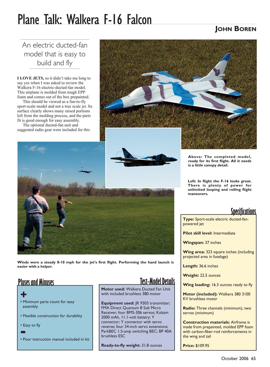
An electric ducted-fan model that is easy to build and fly
I love jets, so it didn't take long to say yes when I was asked to review the Walkera F-16 electric-ducted-fan model. The airplane is molded from tough EPP foam and comes out of the box prepainted. This should be viewed as a fun-to-fly sport-scale model and not a true scale jet. Its surface shows many raised portions left from the molding process, and the parts fit is good enough for easy assembly.
The optional ducted-fan unit and suggested radio gear were included for this review. The stock Falcon kit comes with a pusher propeller system. In addition to the F-16, I reviewed two items from FMA Direct: a Kokam 2000 mAh, three-cell, 11.1-volt Cellpro Super High Discharge Li-Poly battery to power the motor, and a Quantum 8 (item 508FM72) Sub Micro Receiver to control the model in the air.
Pluses and Minuses
- Minimum parts count for easy assembly
- Flexible construction for durability
- Easy to fly
- Poor instruction manual included in kit
Test-Model Details
- Motor used: Walkera Ducted Fan Unit with included brushless 380 motor
- Equipment used: JR 9303 transmitter; FMA Direct Quantum 8 Sub Micro Receiver; four BMS-306 servos; Kokam 2000 mAh, 11.1-volt battery; Y connector; Y connector with servo reverse; four 24-inch servo extensions; ParkBEC 1.5-amp switching BEC; BP 40A brushless ESC
- Ready-to-fly weight: 31.8 ounces
Specifications
- Type: Sport-scale electric ducted-fan-powered jet
- Pilot skill level: Intermediate
- Wingspan: 37 inches
- Wing area: 323 square inches (including projected area in fuselage)
- Length: 36.6 inches
- Weight: 22.5 ounces
- Wing loading: 16.3 ounces ready to fly
- Motor (included): Walkera 380 3100 KV brushless motor
- Radio: Three channels (minimum), two servos (minimum)
- Construction materials: Airframe made from prepainted, molded EPP foam with carbon-fiber-rod reinforcements in the wing and tail
- Price: $109.95
Construction
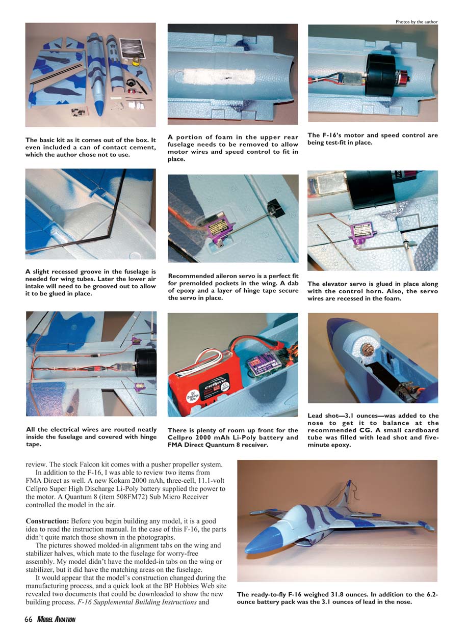
Before beginning any build, read the instruction manual. On this F-16 the parts didn't quite match the photographs: the pictures showed molded-in alignment tabs on the wing and stabilizer halves, but my kit lacked those tabs (the matching areas remained on the fuselage). It appears the model's construction changed during manufacturing. BP Hobbies' website has two downloadable supplements that you will need: F-16 Supplemental Building Instructions and Aileron/Elevator Upgrade Instructions. It would be helpful if these were included in the kit.
Fan unit assembly took several hours and many false attempts before obtaining a reliably running unit. Balancing the rotor was quick. An aluminum propeller adapter secured to the motor shaft caused the fan blades to rub on the shroud in my unit; a replacement adapter solved the problem. It is almost impossible to tighten the nut to secure the rotor unless the adapter is prevented from rotating—cutting a slot in the face of the propeller adapter for a large screwdriver to hold it while tightening the nut with a wrench is strongly suggested.
Do not test-run the fan unit in your hand. Place it inside the upper and lower fuselage halves when test-running to avoid distorting the fan housing and creating tight or uneven clearances between the impeller and shroud.
When fitting the fan into the fuselage, note that the recommended ESC's motor wires are extremely short and only allow the ESC to sit right in front of the fan. Remove foam to recess the ESC into the fuselage so the wires and ESC fit neatly. Once test-fitted, set the fan aside until final installation.
For the airframe I started with the two horizontal stabilizers using the Aileron/Elevator Upgrade Instructions. Steps included:
- Cut 2 inches off the rear of each stabilizer half.
- Bevel the leading edge of both elevators.
- Reattach elevators with your preferred hinge tape.
- Line up the rear edges of the stabilizers with the rear edge of the fuselage, choosing locations where carbon rods can enter the fuselage without hitting later-mounted servos.
- Make small spar cutouts on the bottom of each stabilizer so approximately 1/2 inch of the carbon rod sticks past the root section; recess the spar extension for a secure bond.
The kit includes two large carbon-fiber tubes glued into premade slots in the wing halves. Insert the wing tubes so the root ends meet at the center of the fuselage, following the supplemental alignment instructions. I used polyurethane glue to bond the spars in the wing and stabilizer halves—only a small amount is needed because polyurethane glue expands as it cures. Mark the wing halves for accurate adhesive placement and place weights on parts while drying to keep them flat.
Mark and cut the fuselage where the wing tubes and stabilizer rods enter, and recess the wing tubes into the bottom of the fuselage. Secure the wing halves with five-minute epoxy, ensuring the fuselage and wings sit flat on the building board. Mount the stabilizer with five-minute epoxy and align by placing a small weight on the stabilizers above the mounting area. Glue the vertical stabilizer to the rear upper fuselage; a square can help ensure it dries at 90° to the building surface.
The recommended servo mounting method is glue. Apply a layer of clear tape to the servos where the glue will contact them. Center the servo output shafts and secure the servo arms. BMS-306 servos fit the molded pockets on the bottom of each wing panel. Cut additional room in the rear fuselage to accommodate the elevator servos and secure them with a small dab of five-minute epoxy. Align and epoxy the control horns in place.
You will need to supply two additional music-wire pushrods for the elevators. Four 24-inch servo extensions are required to reach the front-mounted receiver; tape the extensions neatly along the fuselage interior. I used a standard Y-harness to connect the aileron servos and a Y-harness with servo reverse for the two elevator servos. I made a 10-inch battery-extension wire to bring the battery connection to the front cockpit area and taped the ESC wires along the inside of the fuselage for a neat installation.
Epoxy the fan unit to the upper fuselage. The top portion of the air intake required two grooves to be cut so it would lay over the carbon-fiber wing tubes and sit flush with the bottom of the upper forward fuselage. Glue the molded hatch latches into the premolded pockets in the canopy area. The bottom fuselage panels and rear upper canopy hatch cover were tapped in place; I left them unglued pending test flights.
A ParkBEC regulator included in the review was installed inline between the ESC radio connection and the receiver after soldering the red and black power wires to the battery harness. Position the receiver and battery as far forward in the cockpit area as possible. I added 3.1 ounces of lead ballast to the nose to bring the balance point to the recommended 6 inches behind the wing leading edge.
Flying
The first flight day was bright and sunny with a steady 8–10 mph wind. My friend Tom provided the first hand launch while I kept both hands on the transmitter. The first attempt ended after a couple of seconds due to insufficient up-elevator travel to maintain flight. I increased elevator control movement and, on the second attempt a minute later, the F-16 climbed out with no problem—although I had to add almost full up-trim on the transmitter to maintain level flight, suggesting the recommended balance point may be conservative.
Thirty seconds later I handed the controls to my friend so I could take in-flight photos. He reported that the jet flew tremendously, and five minutes later the F-16 made a beautiful slow landing.
Control throws were set at 5/8 inch up and down on the elevator and 1/2 inch up and down on the ailerons. An hour later, with a fully recharged battery, I launched the model myself and it climbed to altitude without issue.
With the provided Walkera Ducted Fan Unit and motor, the F-16 easily performs inside and outside loops from level flight and has a very nice roll rate. Inverted flight is easy, though it required significant down-stick to compensate for the needed up-trim. I estimate the Falcon’s top speed at roughly 50 mph. It isn't a hot rod, but it looks and feels like a jet in the air.
The FMA Quantum 8 Sub Micro Receiver worked perfectly. I tend to keep the throttle about three-quarters open during most of the flight and use full throttle for short bursts during maneuvers or fast flybys.
The motor pulls more than 35 amps static, which pushes my Kokam 2000 mAh, 11.1-volt battery close to its limits—the battery felt extra warm after a flight. A larger battery would help handle the current draw and also provide the additional nose weight needed to reach the correct CG point.
Summary
The Walkera F-16 kit as furnished could use better instructions, but supplemental instructions are available for download on the BP Hobbies website. If you purchase the available upgrade kit, you will have almost everything needed to get the airplane into the air, minus a battery and receiver. Overall, the model was an easy build because of the low parts count. Flight performance is great, with plenty of power to perform almost any maneuver an airplane without a rudder can perform.
John Boren [email protected]
Distributor
BP Hobbies 140 Ethel Rd. W. Suite J Piscataway, NJ 08854 (732) 287-3933 www.bphobbies.com
Items Used in Review
- FMA Quantum 8 receiver; Kokam 2000 mAh, 11.1-volt Li-Poly battery — www.fmadirect.com
- JR 9303 transmitter — www.horizonhobby.com
Transcribed from original scans by AI. Minor OCR errors may remain.

