
Power Switch: Futaba 12Z Radio Control System
Take advantage of the latest in RC-system fidelity and programming flexibility
STEVE KALUF
The newest transmitter offered by Futaba Corporation is the 12Z. It replaces the recently discontinued, tried-and-true 9Z, which had been the standard for competition pilots flying Futaba systems for a long time. Its discontinuation left some large shoes to be filled.
The 9Z was also popular with the higher-end sport pilots who fly many of the same aircraft as competition pilots but generally don't compete. Futaba released the 14MZ slightly more than a year ago; it has been touted as, and certainly seems to be, the highest-end and most advanced transmitter available today.
Does the 12Z fill the shoes vacated by the 9Z without stepping on the toes of the 14MZ? It fills the shoes and does step ever so lightly on the 14MZ's toes. The 12Z's features far surpass the 9Z, and while the 14MZ is easier to program and has some additional amenities (color backlit touchscreen and MP3 player), the 12Z shares many of the 14MZ's capabilities. In this review I will evaluate the 12Z on its own terms.
Looking at the outside of the 12Z
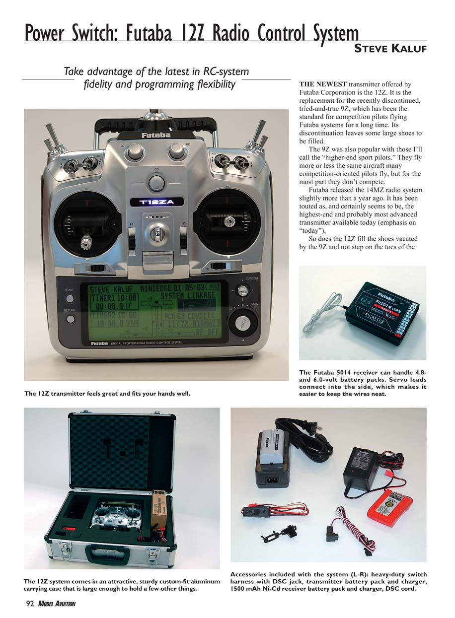
I was extremely impressed with the case's overall fit and finish. The quality of transmitter-case material used in today's top-end transmitters is excellent, and the 12Z is a cut above most. Holding it gives you an immediate sense of quality — the feel in your hands, the look, and the quality of the switches are all notable. Small details, such as a ratchet on the battery-cover door, add to the overall impression.
The overall layout follows Futaba's three top-line transmitters: the 9C, 12Z, and 14MZ. The sticks are silky smooth, and the tension is easy to modify externally on the back of the transmitter. The 12Z has the easiest-to-adjust sticks of any transmitter I have used. You can also switch between ratchet and no ratchet on the throttle stick using a different adjustment; the modification allows a light amount of ratchet if preferred. This makes switching between the ratchet preferred by fixed-wing pilots and the no-ratchet preferred by helicopter pilots simple.
Three fully proportional knobs are positioned across the top front center of the transmitter and may be assigned to almost any function. The last position of the knobs is saved each time you power down; one of the menus displays the saved positions.
Four three-position switches are positioned left and right of top center (two on each side): one long lever and one short lever on each side. Their most typical function is to provide triple rates and/or exponential rates. Depending on which version of the transmitter you purchase (airplane or helicopter), the switches will be pre-positioned in one of two configurations.
- Airplane version: long two-position and short three-position switches on the right side; long spring-loaded and short two-position switches on the left.
- Helicopter version: these switch locations are reversed.
All switches are mounted on a switch block, allowing you to move them between the two blocks to suit the model you are flying. To move a switch: remove the hex-head screw from the top of the block and the small Phillips screw under the rubber handgrip, unplug the wires from the switch, loosen the nut holding the switch to the block, and reposition the switch. The transmitter’s software then lets you tell it the switch’s new location. Early firmware had a slight glitch in recognizing moved switches; this was planned to be fixed in the first software update.
Two slide levers on the top back of the transmitter provide proportional control of two channels and are easy to access with a finger. The rotary knobs, slide levers, and trim buttons beep when the center location is reached.
Four digital trim levers are positioned to the sides and bottom of the joysticks. Although normally assigned to the four functions provided by the joysticks, these trims can be reassigned to almost any other function. Trim positions are retained for each model.
Front and center is a T12ZA(H) logo that doubles as an LED status monitor. During power-up it displays different colors as software loads; once loaded it turns to a solid pink. If you plug the Direct Servo Control (DSC) cable into the transmitter, the logo turns blue. If a different RF module is plugged in, the logo blinks red. When transmitting in normal use, the logo turns green.
The large LCD occupies the front bottom of the transmitter. On the right side of the display are the rotary data dial and the cursor-movement joystick for navigating menus and entering/modifying data. On the left side are two small buttons: the bottom is "Return" (like a browser Back button) that steps up one menu level; the top is "Home," which returns immediately to the main screen.
The LCD is large and clear in most lighting conditions but is not backlit, so you need some ambient light to read it. The display provides a host of information (described below).
Opening the left-side rubber handgrip reveals the CF card slot. The CF card is optional; installing a 32MB card provides storage for more than 250 models. More importantly, the CF card allows firmware updates: download the update from Futaba's 12Z website, install the card in the transmitter, and hit the update switch. The CF card also allows sharing of model programs with other users.
The antenna stores in the bottom of the transmitter in a spring-loaded compartment. Pushing the antenna into the storage area locks it; press a button to release it and the spring pushes it out. For operation the antenna screws into the mount on top of the transmitter and its angle can be adjusted by loosening the hex-head bolt on the left side of the antenna holder.
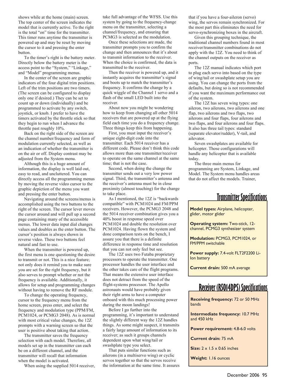
The transmitter battery is a 7.4-volt, 2200 mAh Lithium-Ion pack similar to those used in video cameras. The supplied charger is of the same type. The battery slips out the back of the transmitter and onto the charger; charging takes roughly one hour. Run time is excellent — in my tests the transmitter operated for more than four hours before recharging and still showed approximately 30% remaining. The LCD displays remaining battery power as a percentage and appears accurate.
System includes
- Synthesized transmitter
- 50 or 72 MHz MZ-FM module
- R5014DPS 72 MHz receiver
- 7.4-volt, 2200 mAh Lithium-Ion transmitter battery
- Lithium-Ion transmitter battery charger
- 1500 mAh Ni-Cd receiver battery
- Wall charger for receiver battery
- Direct Servo Control (DSC) cable
- Switch harness with charge cord
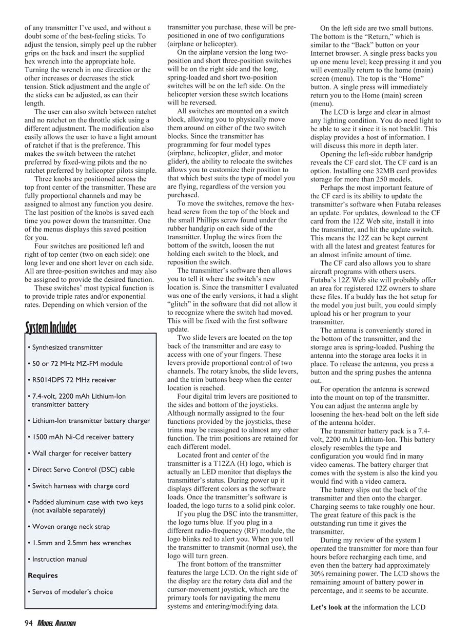
- Padded aluminum case with two keys (not available separately)
- Woven orange neck strap
- 1.5mm and 2.5mm hex wrenches
- Instruction manual
Requires:
- Servos of modeler’s choice
Home screen and LCD information
The home (main) screen displays a large amount of information clearly and uncluttered. Key items:
- Top center: the model that is currently active.
- To the right: total "on" time for the transmitter (runs whenever powered up); move cursor to it and press enter to reset.
- Right of that: battery meter.
- Directly below the battery meter: access to the "System," "Linkage," and "Model" programming menus.
- Center: graphic indicators of the four digital trim positions.
- Left of trims: two timers (screen can display only one if desired). Timers can count up or down individually and be programmed to activate by any switch, joystick, or knob. I prefer to have timers activated by the throttle stick so they begin when throttle passes roughly 10%.
- Right side: channel number/frequency, modulation type (PPM/FM, PCM1024, or PCMG3 2048), and indication of whether the transmitter is on the air or off. Display contrast can be adjusted from the System menu.
You can directly access programming menus by moving the reverse-video cursor to the graphic depiction of the menu and pressing enter. Navigation is accomplished using the cursor lever and the lower data input dial (which changes values and doubles as the enter button). The cursor's position shows in reverse video. These controls feel natural and fast to use.
When powered up, the transmitter first asks whether you want to transmit or not. This prompts you to confirm frequency and availability and also allows setup/programming changes without installing the RF module.
Frequency selection and WFSS
To change operating frequency, move the cursor to the frequency menu from the home screen, press enter, and select the frequency and modulation type (PPM/FM, PCM1024, or PCMG3 2048). Critical changes prompt a warning screen.
The transmitter saves frequency selection with each model, so different models can be set to different channels and the transmitter will recall each when the model is activated.
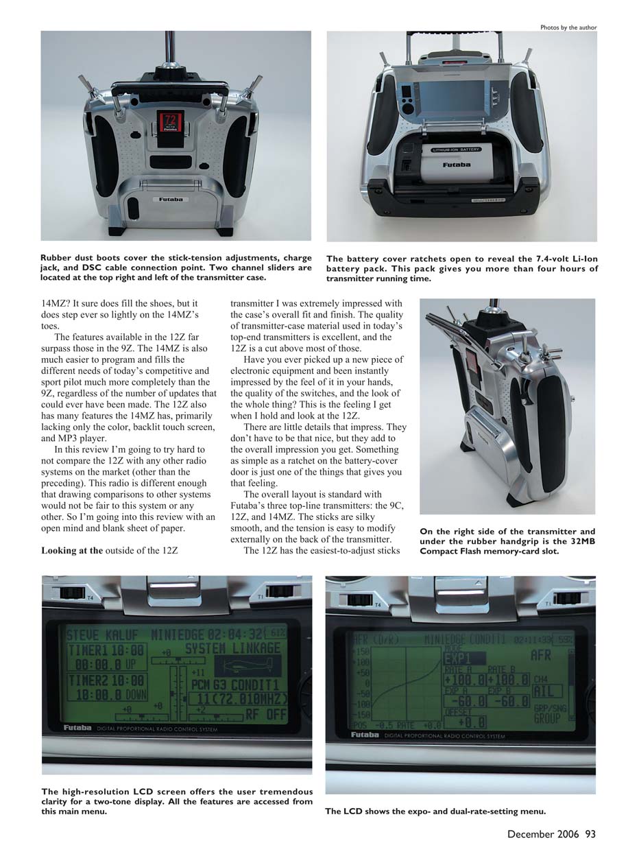
When using the supplied R5014 receiver, take full advantage of WFSS (Wireless Frequency Set System). From the frequency-change menu select a channel/frequency and ensure PCMG3 modulation is selected. The transmitter prompts confirmation and then transmits the information to the receiver. Power up the receiver with its unique eight-digit code programmed into the transmitter, and the receiver acquires the transmitter's signal and boots up to match the frequency. It confirms by a quick wiggle of the Channel 1 servo and a flash of the receiver LED.
To avoid inadvertently changing other R5014 receivers at the flying field: each receiver has a unique eight-digit code that must be input into the transmitter; the transmitter sends only a very low-power signal when changing frequencies; and the transmitter and receiver antennas must be in close proximity (almost touching) for the change to take place.
The 12Z is backwards compatible with PCM1024 and FM/PPM receivers. However, the PCMG3 2048 and the R5014 receiver combination gives a roughly 40% boost in response speed over PCM1024 and double the resolution. Bench and flight tests show a definite, noticeable improvement in response time and resolution.
Processors, channel grouping, and receiver ports
The 12Z uses two proprietary processors: one handles the user interface and the other handles the flight programs. This separation ensures the extensive user interface does not detract from flight-systems speed.
Because the 12Z transmits a large amount of information to the receiver, it groups channels depending on wing/tail or swashplate type. Grouping puts similar functions (e.g., ailerons in a multiservo wing or cyclic servos) together so servos receive information simultaneously, which helps keep multiservo wings synchronized and largely eliminates the need for servo-synchronizing boxes.
Given this grouping, traditional channel numbers do not directly apply; think of the receiver outputs as ports. The 12Z manual indicates which port to plug each servo into based on wing/tail or swashplate setup. You can change ports from defaults, but doing so is not recommended if you want maximum performance.
The 12Z supports multiple configurations:
- Wing types (7): one aileron; two ailerons; two ailerons + one flap; two ailerons + two flaps; two ailerons + four flaps; four ailerons + two flaps; four ailerons + four flaps.
- Tail types (3): standard (separate elevator/rudder), V-tail, elevator.
- Swashplates (7) for helicopters: configurations to handle any helicopter available today.
Programming menus
The three main programming menus are:
- System: handles areas that do not affect individual models (sound, user name, display, system timer, H/W reverse, information, etc.).
- Linkage: select model, model type, wing/swashplate type, frequency selection, end points, subtrims, function assignments (assign channels to functions), failsafe, servo reversing, and more. Linkage also contains a Servo Monitor screen for monitoring each channel and provides two tests: Moving Test (cycles each channel) and Neutral Test (locks channels in neutral to center servos).
- Model: used for the majority of programming for each aircraft. Model Select lets you choose a model from internal memory or CF card, add, name, or copy models.
Common Model menu functions include Servo Monitor, Condition Select, AFR (dual rate/expo), Programmable Mix, and Fuel Mixture.
When a fixed-wing model is selected, additional functions may include:
- Aileron Differential, Flap Setting, Aileron to Camber Flaps, Aileron to Brake Flaps, Aileron to Rudder, Airbrake to Elevator, Rudder to Aileron, Camber Mix, Elevator to Camber, Camber Flap to Elevator, Butterfly (Crow), Trim Mix 1 and 2, Airbrake, Gyro, V-tail, Ailevator, Winglet, Motor, Rudder to Elevator, Snap Roll, Multi-Engine.
Helicopter menus include:
- Pitch Curve, Throttle Curve, Acceleration, Throttle Hold, Swash Mix, Throttle Mix, Pitch to Needle, Pitch to Rudder, Fuel Mixture, Gyro, Governor.
Curves and mixing
The 12Z makes extensive use of curves for mixing functions. Multiple curve types are available and make it easy to fine-tune models. In helicopter mode you can have as many as 17 curve points. Curve points can be added or deleted. Available curve types include Line, Linear, Spline, Expo, and VTR. The high-resolution display shows curves graphically, which is helpful for setup.
Manual, usability, and programming experience
This system was designed to be comfortable to hold, with logically laid out controls. Size and weight feel right, and the feature list is extensive; there is little I can think of that the transmitter cannot do.
The weakest point was the manual. Although adequate, it lacked depth and a clear overview of the 12Z system. At times the manual did not clearly direct the user to the next programming step (for example, how to reach the screen for making switch selections when setting Dual Rates or Expo). Because the system is logically arranged, most users can figure things out with a bit of exploration. The review unit was one of the first 12Zs available, so the manual may have been a work in progress.
During the review I programmed two fixed-wing models and two helicopters. Programming was generally intuitive and fast — once model type is set, much of the configuration is already laid out. After about two weeks and roughly eight hours of hands-on time, I was comfortable programming almost any function on the 12Z without the manual and found myself preferring some tasks on the 12Z over my current transmitter.
Price and recommendation
The 12Z has a street price of approximately $1,400 with the R5014 receiver included. That may seem expensive, but the system is worth the cost. Very few systems offer the flexibility, ease of programming, and features of the 12Z. It is worth serious consideration.
Contact: [email protected]
Transmitter specifications
- Model types: Airplane, helicopter, glider, motor glider
- Operating system: Two-stick, 12-channel, PCMG3 synthesizer system
- Modulation: PCMG3, PCM1024, or FM/PPM switchable
- Power supply: 7.4-volt 2200 mAh Li-Ion battery
- Current drain: 500 mA average
Receiver (R5014DPS) specifications
- Receiving frequency: 72 or 50 MHz bands
- Intermediate frequency: 10.7 MHz and 450 kHz
- Power requirement: 4.8–6.0 volts
- Current drain: 75 mA
- Size: 2 x 1.5 x 0.65 inches
- Weight: 1.16 ounces
Manufacturer/Distributor: Great Planes Hobby Distributors Inc. Box 9021 Champaign, IL 61826 (217) 398-8970 www.futaba-rc.com/radios/futj9300.html
Transcribed from original scans by AI. Minor OCR errors may remain.

