
Product Review
Joe Beshar 198 Merritt Dr., Oradell, NJ 07649
Upon receipt of the cartons containing the Hangar 9 Taylorcraft’s parts, I was impressed with the attractive and sturdy packaging. The outside carton had been badly damaged during shipment, so I opened it—while holding my breath—to find no damage to the model components because everything was efficiently packed. All parts were bagged, ranging from the largest piece to the smallest hardware. Save the box; the pictorial renderings around it are helpful for referencing details during construction.
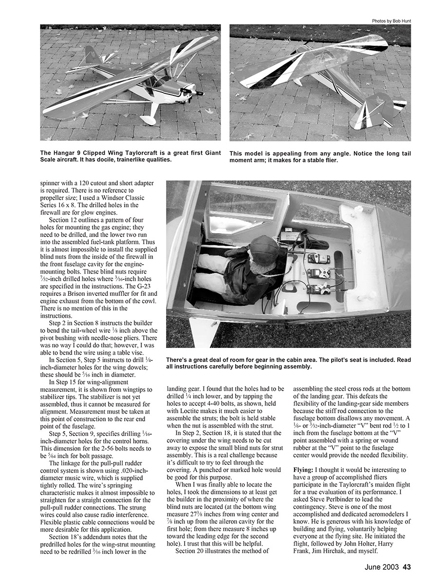
The Taylorcraft will be well received not only by the Giant Scale enthusiast; my immediate reaction was that, with its scale appearance and size, it would be the ideal candidate for the glow-flying sport flier to graduate to gas power and into the Giant Scale arena. After completing and flying the Taylorcraft, my initial feeling was endorsed as reality. For that reason, I am covering the gas-powered Taylorcraft in this review.
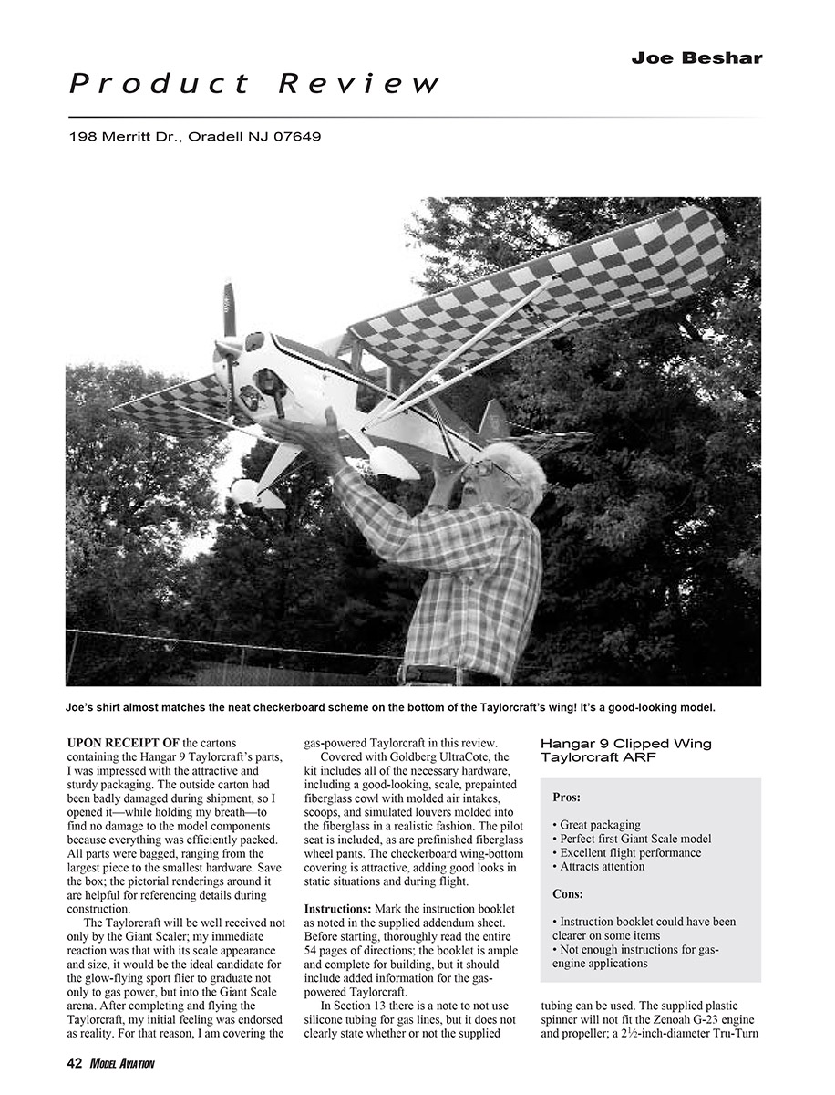
Covered with Goldberg UltraCote, the kit includes all necessary hardware, including a good-looking, scale, pre-painted fiberglass cowl with molded air intakes, scoops, and simulated louvers molded into the fiberglass in a realistic fashion. The pilot seat is included, as are prefinished fiberglass wheel pants. The checkerboard wing-bottom covering is attractive, adding good looks in static situations and during flight.
Instructions and Assembly Notes
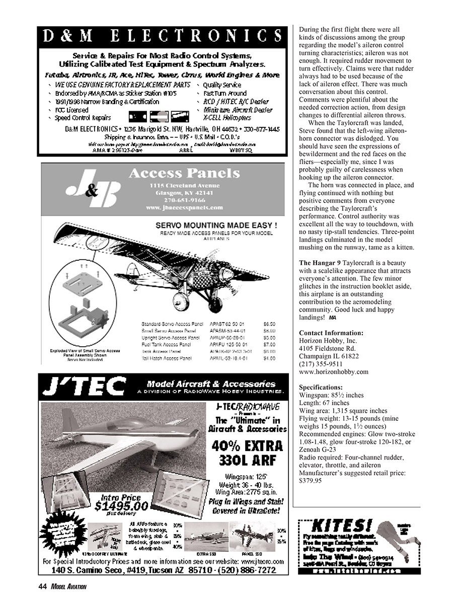
Mark the instruction booklet as noted in the supplied addendum sheet. Before starting, thoroughly read the entire 54 pages of directions; the booklet is ample and complete for building, but it should include added information for the gas-powered Taylorcraft.
- Section 13 notes not to use silicone tubing for gas lines, but it does not clearly state whether the supplied tubing can be used.
- The supplied plastic spinner will not fit the Zenoah G-23 engine and propeller; a 2-1/2-inch-diameter Tru-Turn spinner with a .120-inch cutout and a short adapter is required.
- There is no reference to propeller size; I used a Windsor Classic Series 16x8.
- The drilled holes in the firewall are for glow engines. Section 12 outlines a pattern of four holes for mounting the gas engine; they need to be drilled, and the lower two run into the assembled fuel-tank platform. Thus it is almost impossible to install the supplied blind nuts from the inside of the firewall in the front fuselage cavity for the engine-mounting bolts.
- These blind nuts require 7/32-inch drilled holes where 3/16-inch holes are specified in the instructions.
- The G-23 requires a Brison inverted muffler for fit and engine exhaust from the bottom of the cowl. There is no mention of this in the instructions.
Specific construction corrections and clarifications:
- Step 2, Section 8 instructs the builder to bend the tail-wheel wire 1/8 inch above the pivot bushing with needle-nose pliers. This was impractical; I was able to bend the wire using a table vise.
- In Section 5, Step 5 instructs to drill 1/4-inch-diameter holes for the wing dowels; these should be 5/16 inch in diameter.
- In Step 15 for wing-alignment measurement, the drawing shows measuring from wingtips to stabilizer tips. The stabilizer is not yet assembled at that point, so measure instead to the rear end point of the fuselage.
- Step 5, Section 9 specifies drilling 1/16-inch-diameter holes for the control horns. This dimension for the 2-56 bolts needs to be 5/64 inch for bolt passage.
- The linkage for the pull-pull rudder control system is shown using .020-inch-diameter music wire, which is supplied tightly rolled. The wire's springing characteristic makes it almost impossible to straighten for a true straight connection for the pull-pull rudder. The strung wires could also cause radio interference. Flexible plastic cable connections would be more desirable for this application.
Section 18 addendum notes that the predrilled holes for the wing-strut mounting need to be redrilled 3/16 inch lower in the landing gear. I found the holes had to be drilled 1/4 inch lower; tapping the holes to accept 4-40 bolts, as shown and held with Loctite, makes it much easier to assemble the struts—the bolt is held stable when the nut is assembled with the strut.
In Step 2, Section 18, it is stated that the covering under the wing needs to be cut away to expose the small blind nuts for strut assembly. This is challenging because it's difficult to feel through the covering. A punched or marked hole would be useful. When I located the holes, I measured to help other builders find them: at the bottom wing measure 2 7/8 inches from wing center and 7/8 inch up from the aileron cavity for the first hole; from there measure 8 inches toward the leading edge for the second hole.
Section 20 illustrates assembling the steel cross rods at the bottom of the landing gear. This defeats the flexibility of the landing-gear side members because the stiff rod connection to the fuselage bottom disallows movement. I recommend using a 1/16- or 3/32-inch-diameter V-bent rod, bent 1/2 to 1 inch from the fuselage bottom at the V point, and assembled with a spring or wound rubber at the V point to the fuselage center to provide the needed flexibility.
Hangar 9 Clipped Wing Taylorcraft ARF
Pros:
- Great packaging
- Perfect first Giant Scale model
- Excellent flight performance
- Attracts attention
Cons:
- Instruction booklet could be clearer on some items
- Not enough instructions for gas-engine applications
Flying
I thought it would be interesting to have a group of accomplished fliers participate in the Taylorcraft's maiden flight for a true evaluation of its performance. I asked Steve Perlbinder to lead the contingency. Steve is one of the most accomplished and dedicated aeromodelers I know. He is generous with his knowledge of building and flying, voluntarily helping everyone at the flying site. He initiated the flight, followed by John Holter, Harry Frank, Jim Hirchak, and myself.
During the first flight there was much discussion among the group regarding the model's aileron control turning characteristics; the aileron alone was not enough. It required rudder movement to turn effectively. Claims were that rudder always had to be used because of the lack of aileron effect. There was much conversation about this control, with suggested corrections ranging from design changes to differential aileron throws.
When the Taylorcraft was landed, Steve found that the left-wing aileron-horn connector was dislodged. You should have seen the expressions of bewilderment and the red faces on the fliers—especially mine, since I was probably guilty of carelessness when hooking up the aileron connector.
The horn was reconnected, and flying continued with nothing but positive comments from everyone describing the Taylorcraft's performance. Control authority was excellent all the way to touchdown, with no nasty tip-stall tendencies. Three-point landings culminated in the model mushing on the runway—tame as a kitten.
The Hangar 9 Taylorcraft is a beauty with a scale appearance that attracts everyone's attention. The few minor glitches in the instruction booklet aside, this airplane is an outstanding contribution to the aeromodeling community. Good luck and happy landings!
Contact Information
Horizon Hobby, Inc. 4105 Fieldstone Rd. Champaign, IL 61822 (217) 355-9511 www.horizonhobby.com
Specifications
- Wingspan: 85½ inches
- Length: 67 inches
- Wing area: 1,315 square inches
- Flying weight: 13–15 pounds (mine weighs 15 pounds, 1½ ounces)
- Recommended engines: Glow two-stroke .10–.48, glow four-stroke .120–.182, or Zenoah G-23
- Radio required: Four-channel—rudder, elevator, throttle, and aileron
- Manufacturer's suggested retail price: $379.95
Transcribed from original scans by AI. Minor OCR errors may remain.

