
Product Review
Steve Kulicki 520 Meadow Ln., Bath, PA 18014
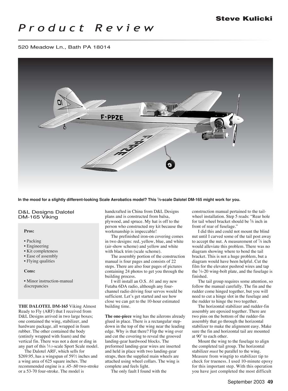
D&L Designs Dalotel DM-165 Viking
Pros:
- Packaging
- Engineering
- Kit completeness
- Ease of assembly
- Flying qualities
Cons:
- Minor instruction-manual discrepancies
The Dalotel DM-165 Viking Almost Ready to Fly (ARF) that I received from D&L Designs arrived in two large boxes. One contained the wing, stabilizer, and hardware package, all wrapped in foam rubber. The other contained the fuselage (entirely wrapped with foam) and the vertical fin. There was not a dent or ding in any part of this 1/5.5-scale sport-scale model.
The Dalotel ARF, which sells for $269.95, has a wingspan of 59 1/2 inches and a wing area of 625 square inches. The recommended engine is a .45–.60 two-stroke or a 53–70 four-stroke. The model is handcrafted in China from D&L Designs plans and is constructed from balsa, plywood, and spruce. My hat is off to the person who constructed my kit because the workmanship is impeccable!
The prefinished iron-on covering comes in two designs: red, yellow, blue, and white (air-show scheme) and yellow and white with black trim (scale scheme).
The assembly portion of the construction manual is four pages and consists of 22 steps. There are also four pages of pictures containing 24 photos to get you through the building process.
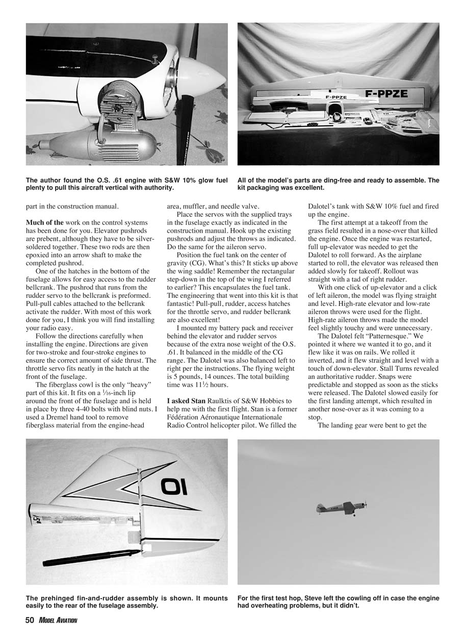
I installed an O.S. .61 and my new Futaba 6DA radio, although any four-channel radio driving four servos would be sufficient. Let's get started and see how close we can get to the 10-hour estimated building time.
The one-piece wing has the ailerons already glued in place. There is a rectangular step-down in the top of the wing near the leading edge. Why is that there? Flip the wing over and cut the covering to reveal the grooved landing-gear hardwood blocks. The preformed landing-gear wires are inserted and held in place with two landing-gear straps, then the supplied main wheels are attached using wheel collars. The wing is complete and feels light.
The only fault I found with the construction manual pertained to the tailwheel installation. Step 5 reads: "Rear hole for tail wheel bracket should be 5/8 inch in front of rear of fuselage." I did this and could not mount the blind nut until I carved some of the tail post away to accept the nut. A measurement of 7/8 inch would alleviate this problem. There was no diagram showing where to bend the tail bracket. This is not a huge problem, but a diagram would have been helpful.
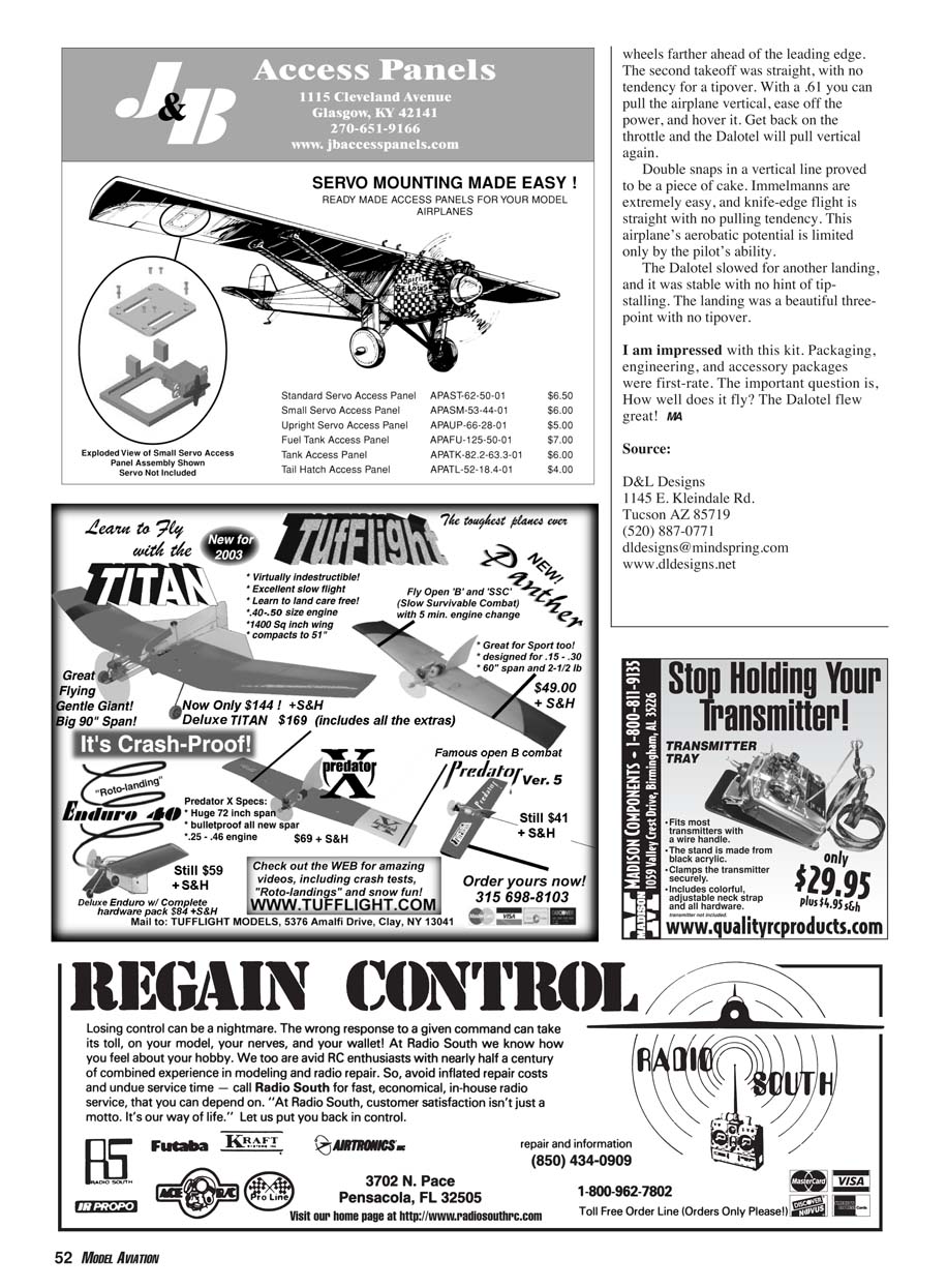
Cut the film for the elevator pushrod wires and tap the 1/4-20 wing-bolt plate, and the fuselage is finished. The tail group requires some attention, so follow the manual carefully. The fin and the rudder come hinged together, but you will need to cut a hinge slot in the fuselage and the rudder to hinge the two together. The horizontal stabilizer and rudder-fin assembly are epoxied together. There are two pins on the bottom of the rudder-fin assembly that go through the horizontal stabilizer to make alignment easy. Make sure the fin and horizontal tail are mounted at 90° to each other. Mount the wing to the fuselage to align the completed tail group. The horizontal stabilizer must be parallel to the wing. Measure from wingtip to stabilizer tip to check for trueness. I used 10-minute epoxy for this important step. With this operation you have just completed the most difficult part in the construction manual.
Much of the work on the control systems has been done for you. Elevator pushrods are pre-bent, although they have to be silver-soldered together. These two rods are then epoxied into an arrow shaft to make the completed pushrod.
One of the hatches in the bottom of the fuselage allows for easy access to the rudder bellcrank. The pushrod that runs from the rudder servo to the bellcrank is preformed. Pull-pull cables attached to the bellcrank activate the rudder. With most of this work done for you, I think you will find installing your radio easy.
Follow the directions carefully when installing the engine. Directions are given for two-stroke and four-stroke engines to ensure the correct amount of side thrust. The throttle servo fits neatly in the hatch at the front of the fuselage.
The fiberglass cowl is the only "heavy" part of this kit. It fits on a 1/16-inch lip around the front of the fuselage and is held in place by three 4-40 bolts with blind nuts. I used a Dremel hand tool to remove fiberglass material from the engine-head area, muffler, and needle valve.
Place the servos with the supplied trays in the fuselage exactly as indicated in the construction manual. Hook up the existing pushrods and adjust the throws as indicated. Do the same for the aileron servo.
Position the fuel tank on the center of gravity (CG). What's this? It sticks up above the wing saddle! Remember the rectangular step-down in the top of the wing I referred to earlier? This encapsulates the fuel tank. The engineering that went into this kit is fantastic! Pull-pull rudder, access hatches for the throttle servo, and the rudder bellcrank are also excellent!
I mounted my battery pack and receiver behind the elevator and rudder servos because of the extra nose weight of the O.S. .61. It balanced in the middle of the CG range. The Dalotel was also balanced left to right per the instructions. The flying weight is 5 pounds, 14 ounces. The total building time was 11 1/2 hours.
I asked Stan Raulits of S&W Hobbies to help me with the first flight. Stan is a former Fédération Aéronautique Internationale radio-control helicopter pilot. We filled the Dalotel's tank with S&W 10% fuel and fired up the engine.
The first attempt at a takeoff from the grass field resulted in a nose-over that killed the engine. Once the engine was restarted, full up-elevator was needed to get the Dalotel to roll forward. As the airplane started to roll, the elevator was released then added slowly for takeoff. Rollout was straight with a tad of right rudder.
With one click of up-elevator and a click of left aileron, the model was flying straight and level. High-rate elevator and low-rate aileron throws were used for the flight. High-rate aileron throws made the model feel slightly touchy and were unnecessary.
The Dalotel felt pattern-esque. We pointed it where we wanted it to go, and it flew like it was on rails. We rolled it inverted, and it flew straight and level with a touch of down-elevator. Stall turns revealed an authoritative rudder. Snaps were predictable and stopped as soon as the sticks were released. The Dalotel slowed easily for the first landing attempt, which resulted in another nose-over as it was coming to a stop.
The landing gear were bent to get the wheels farther ahead of the leading edge. The second takeoff was straight, with no tendency for a tipover. With a .61 you can pull the airplane vertical, ease off the power, and hover it. Get back on the throttle and the Dalotel will pull vertical again.
Double snaps in a vertical line proved to be a piece of cake. Immelmanns are extremely easy, and knife-edge flight is straight with no pulling tendency. This airplane's aerobatic potential is limited only by the pilot's ability.
The Dalotel slowed for another landing, and it was stable with no hint of tip-stalling. The landing was a beautiful three-point with no tipover.
I am impressed with this kit. Packaging, engineering, and accessory packages were first-rate. The important question is, how well does it fly? The Dalotel flew great!
MA
Source: D&L Designs 1145 E. Kleindale Rd. Tucson, AZ 85719 (520) 887-0771 [email protected] www.dldesigns.net
Transcribed from original scans by AI. Minor OCR errors may remain.

