
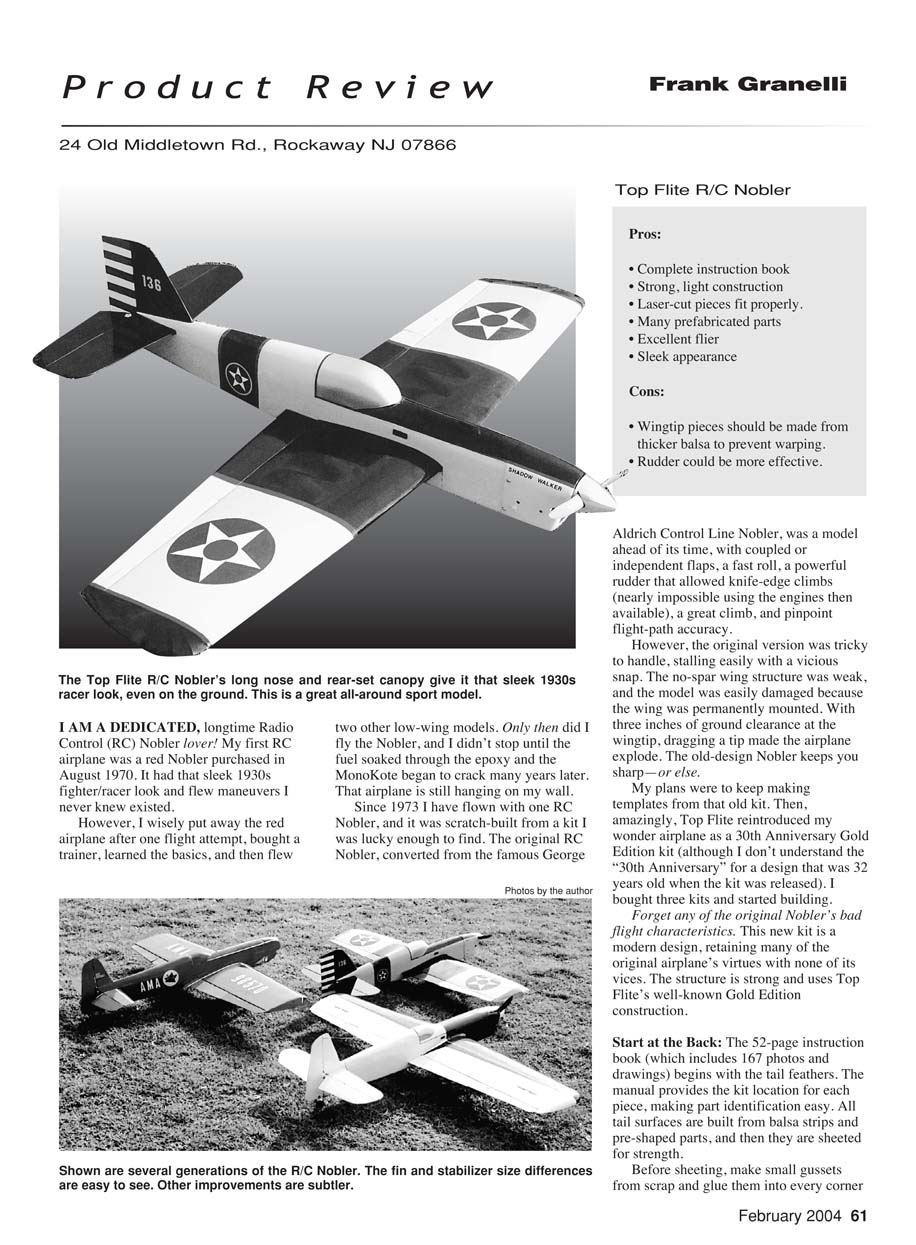
Product Review
Frank Granelli 24 Old Middletown Rd., Rockaway, NJ 07866
I am a dedicated, longtime Radio Control (RC) Nobler lover. My first RC airplane was a red Nobler purchased in August 1970. It had that sleek 1930s fighter/racer look and flew maneuvers I never knew existed.
However, I wisely put away the red airplane after one flight attempt, bought a trainer, learned the basics, and then flew two other low-wing models. Only then did I fly the Nobler, and I didn't stop until the fuel soaked through the epoxy and the MonoKote began to crack many years later. That airplane is still hanging on my wall.
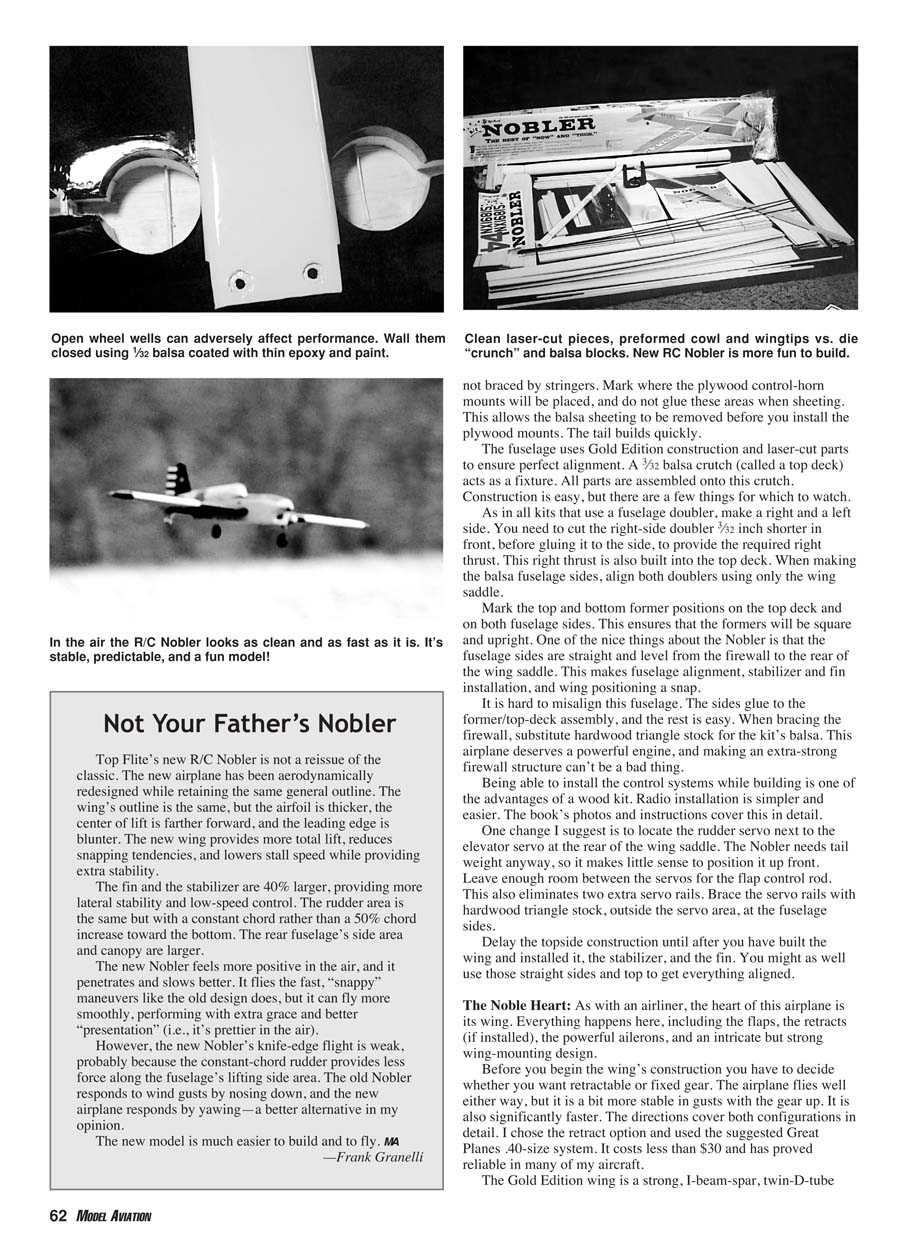
Since 1973 I have flown with one RC Nobler, and it was scratch-built from a kit I was lucky enough to find. The original RC Nobler, converted from the famous George Aldrich control-line Nobler, was a model ahead of its time, with coupled or independent flaps, a fast roll, a powerful rudder that allowed knife-edge climbs (nearly impossible using the engines then available), a great climb, and pinpoint flight-path accuracy.
However, the original version was tricky to handle, stalling easily with a vicious snap. The no-spar wing structure was weak, and the model was easily damaged because the wing was permanently mounted. With three inches of ground clearance at the wingtip, dragging a tip made the airplane explode. The old-design Nobler keeps you sharp—or else.
My plans were to keep making templates from that old kit. Then, amazingly, Top Flite reintroduced my wonder airplane as a 30th Anniversary Gold Edition kit (although I don't understand the "30th Anniversary" for a design that was 32 years old when the kit was released). I bought three kits and started building.
Forget any of the original Nobler's bad flight characteristics. This new kit is a modern design, retaining many of the original airplane's virtues with none of its vices. The structure is strong and uses Top Flite's well-known Gold Edition construction.
Not Your Father's Nobler
Top Flite's new R/C Nobler is not a reissue of the classic. The new airplane has been aerodynamically redesigned while retaining the same general outline. The wing's outline is the same, but the airfoil is thicker, the center of lift is farther forward, and the leading edge is blunter. The new wing provides more total lift, reduces snapping tendencies, and lowers stall speed while providing extra stability.
The fin and the stabilizer are 40% larger, providing more lateral stability and low-speed control. The rudder area is the same but now has a constant chord rather than the original's 50% chord increase toward the tip.
Start at the Back
The 52-page instruction book (which includes 167 photos and drawings) begins with the tail feathers. The manual provides the kit location for each piece, making part identification easy. All tail surfaces are built from balsa strips and pre-shaped parts, and then they are sheeted for strength.
Before sheeting, make small gussets from scrap and glue them into every corner not braced by stringers. Mark where the plywood control-horn mounts will be placed, and do not glue these areas when sheeting. This allows the balsa sheeting to be removed before you install the plywood mounts. The tail builds quickly.
The fuselage uses Gold Edition construction and laser-cut parts to ensure perfect alignment. A 3/32-inch balsa crutch (called a top deck) acts as a fixture; all parts are assembled onto this crutch. Construction is easy, but there are a few things for which to watch.
As in all kits that use a fuselage doubler, make a right and a left side. You need to cut the right-side doubler 3/32 inch shorter in front, before gluing it to the side, to provide the required right thrust. This right thrust is also built into the top deck. When making the balsa fuselage sides, align both doublers using only the wing saddle.
Mark the top and bottom former positions on the top deck and on both fuselage sides. This ensures that the formers will be square and upright. One of the nice things about the Nobler is that the fuselage sides are straight and level from the firewall to the rear of the wing saddle. This makes fuselage alignment, stabilizer and fin installation, and wing positioning a snap.
It is hard to misalign this fuselage. The sides glue to the former/top-deck assembly, and the rest is easy. When bracing the firewall, substitute hardwood triangle stock for the kit's balsa. This airplane deserves a powerful engine, and making an extra-strong firewall structure can't be a bad thing.
Being able to install the control systems while building is one of the advantages of a wood kit. Radio installation is simpler and easier. The book's photos and instructions cover this in detail.
One change I suggest is to locate the rudder servo next to the elevator servo at the rear of the wing saddle. The Nobler needs tail weight anyway, so it makes little sense to position it up front. Leave enough room between the servos for the flap control rod. This also eliminates two extra servo rails. Brace the servo rails with hardwood triangle stock, outside the servo area, at the fuselage sides.
Delay the topside construction until after you have built the wing and installed it, the stabilizer, and the fin. You might as well use those straight sides and top to get everything aligned.
The Noble Heart
As with an airliner, the heart of this airplane is its wing. Everything happens here, including the flaps, the retracts (if installed), the powerful ailerons, and an intricate but strong wing-mounting design.
Before you begin the wing's construction you have to decide whether you want retractable or fixed gear. The airplane flies well either way, but it is a bit more stable in gusts with the gear up. It is also significantly faster. For the retract option I used the suggested Great Planes 40-size system. It costs less than $30 and has proved reliable in many of my aircraft.
The Gold Edition wing is a strong I-beam-spar, twin-D-tube design using a second rear spar as the rib-alignment fixture. Proper rib spacing and alignment are assured because both spars are notched for their companion ribs. Carefully position the spars on the plans, and the wing has to be straight—a nice feature.
Another good quality is the clever wing design that provides the performance features of a double-tapered wing without the construction hassle usually associated with it. The wing's real trailing edge is straight, allowing easy construction and alignment, but the flaps and ailerons taper, making the completed wing the fast-rolling, precision-flying structure that it is.
As always when building a wooden wing, weigh the wing ribs and put the heaviest of each pair on the right side, opposite the muffler. This reduces the need for wingtip weight. Do the same later with the wing sheeting.
The wing builds fairly quickly, seeming to "fly" together, but you need to pay special attention to a few details. During construction use scrap 1/16-inch spacers between W1 and W2 to make sure that there will be room during wing assembly for the spar joiners.
If you are installing retracts, you will notice that the gear-mounting rail has to be cut nearly through to make room for the leg spring when retracted. Brace this rail with another rail epoxied underneath and to the wing ribs.
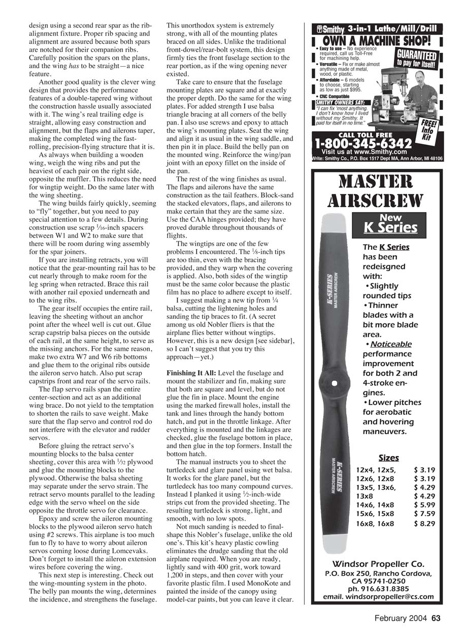
The gear itself occupies the entire rail, leaving the sheeting without an anchor point after the wheel well is cut out. Glue scrap capstrip balsa pieces on the outside of each rail, at the same height, to serve as the missing anchors. For the same reason, make two extra W7 and W6 rib bottoms and glue them to the original ribs outside the aileron servo hatch. Also put scrap capstrips front and rear of the servo rails.
The flap servo rails span the entire center section and act as an additional wing brace. Do not yield to the temptation to shorten the rails to save weight. Make sure that the flap servo and control rod do not interfere with the elevator and rudder servos.
Before gluing the retract servo's mounting blocks to the balsa center sheeting, cover this area with 1/32-inch plywood and glue the mounting blocks to the plywood. Otherwise the balsa sheeting may separate under the servo strain. The retract servo mounts parallel to the leading edge with the servo wheel on the side opposite the throttle servo for clearance.
Epoxy and screw the aileron mounting blocks to the plywood aileron servo hatch using #2 screws. This airplane is too much fun to fly to have to worry about aileron servos coming loose during Lomcevaks. Don't forget to install the aileron extension wires before covering the wing.
Check out the wing-mounting system: the belly pan mounts the wing, determines the incidence, and strengthens the fuselage. This unorthodox system is extremely strong, with all of the mounting plates braced on all sides. Unlike the traditional front-dowel/rear-bolt system, this design firmly ties the front fuselage section to the rear portion, as if the wing opening never existed.
Take care to ensure that the fuselage mounting plates are square and at exactly the proper depth. Do the same for the wing plates. For added strength I use balsa triangle bracing at all corners of the belly pan. I also use screws and epoxy to attach the wing's mounting plates. Seat the wing and align it as usual in the wing saddle, and then pin it in place. Build the belly pan on the mounted wing. Reinforce the wing/pan joint with an epoxy fillet on the inside of the pan.
The rest of the wing finishes as usual. The flaps and ailerons have the same construction as the tail feathers. Block-sand the stacked elevators, flaps, and ailerons to make certain that they are the same size. Use the CAA hinges provided; they have proved durable throughout thousands of flights.
The wingtips are one of the few problems I encountered. The 1/8-inch tips are too thin, even with the bracing provided, and they warp when the covering is applied. Also, both sides of the wingtip must be the same color because the plastic film has no place to adhere except to itself. I suggest making a new tip from 1/4-inch balsa, cutting the lightening holes and sanding the tip braces to fit. A secret among old Nobler fliers is that the airplane flies better without wingtips. However, this is a new design, so I can't recommend trying this approach yet.
Finishing It All
Level the fuselage and mount the stabilizer and fin, making sure that both are square and level, but do not glue the fin in place. Mount the engine using the marked firewall holes, install the tank and lines through the handy bottom hatch, and put in the throttle linkage. After everything is mounted and the linkages are checked, glue the fuselage bottom in place, and then glue in the top formers. Install the bottom hatch.
The manual instructs you to sheet the turtledeck and glare panel using wet balsa. It works for the glare panel, but the turtledeck has too many compound curves. Instead I planked it using 1/16-inch-wide strips cut from the provided sheeting. The resulting turtledeck is strong, light, and smooth, with no low spots.
Not much sanding is needed to finalize the Nobler's fuselage, unlike the old one's. This kit's heavy plastic cowl eliminates the drudge sanding that the old airplane required. When you are ready, lightly sand with 400 grit, work toward 1,200 in steps, and then cover with your favorite plastic film. I used MonoKote and painted the inside of the canopy using model-car paints, but you can leave it clear.
Engine and Radio
The Great Planes adjustable engine mount easily fits my Webra 50, which weighs 11 ounces and turns an APC 11 x 6 propeller near 13,000 rpm on 15% sport fuel. The finished model weighs 5 pounds, 2 ounces—only 4 ounces more than the older fixed-gear version shown. Any .40 engine would perform well, but, as the directions ask, why put a small engine in an aircraft that was so clearly meant to fly?
JR's trusty XF 652 radio provides the guidance with plain 517 sport servos for muscle. I like the 652 in performance airplanes since it provides rudder/elevator mixing to remove knife-edge "walking" and allows the flaps to be coupled with the elevator and/or be independently lowered. The 700 mAh battery mounts behind the wing saddle.
Stretching the Sky
It was a cold, windy day, but I didn't care; I was going to fly a new Nobler for the first time in 10 years. The engine worked perfectly, everything was balanced laterally and at the center of gravity, the radio worked, and the sky brightened as "Shadow Walker" started rolling over the runway.
Liftoff was reached before full throttle, and that got my attention. Doing that with the old Nobler meant a great deal of rudder to stop the coming snap roll. This time there was nothing except a smooth climbout. During the first climbing turn I noticed extra yaw stability lacking in the old design. The airplane just felt more solid and did not need the usual rudder inputs.
After trimming three clicks down and one right on the first pass, I turned the Nobler back at 75% power and pulled up the wheels. The airplane leapt ahead, and then I went to 100%, accelerating in the climb. This is a fast model, and I ended the zoom climb as it became a fast-disappearing dot.
Back down at 200 feet I tested both knife edges for "walking." Little elevator trim was needed, probably because the Nobler was designed when airframes—not computer radios—had to compensate for this. There was no rudder coupling. Coupled flaps made for 30-foot square loops at low throttle.
The time came to land and to use those big flaps. I used 40°, dropped the gear, and there was no pitch change at less than 75% power. The airplane slowed like it was flying in syrup, taking a steep approach path. Because of the wind it was hard to judge landing speed, but approach and landing were no faster than they would have been for a flat-bottomed trainer in the same conditions. The ground roll was less than 20 feet.
The next takeoff ended in a vertical rolling climb to 500 feet, fast inverted to inverted rolls coming back with an inverted spin turnaround, and a 16-point slow roll across the bottom. Yup, it's still a Nobler. I tried simple 3-D and learned that the flaps made waterfalls and blenders easy. Snap rolls can be fast on high rates but slow enough to be pretty using low rates. Inside or outside avalanches can be gigantic. The airplane just plain looks good in the air, especially with the wheels gone. Low passes can leave you staring at its sleek form passing by.
Even as a new sport design, it would be hard to find a better all-around performer than this. It looks good, flies fast or slow with great control, and performs a wide range of complicated maneuvers with effortless grace. But as an improved return of one of our sport's great classics, it's an opportunity that is too good to miss.
Specifications
- Item number: TOPA0220
- Wingspan: 51 inches
- Wing area: 550 square inches
- Weight: 3.5–5.5 pounds
- Wing loading: 14.7–23.0 ounces per square foot
- Fuselage length: 42.4 inches
- Engine: Two-stroke .25–.50 or four-stroke .40–.52
- Radio: Four- to six-channel with five to seven servos
Distributor
- Great Planes Model Distributors
- Box 9021
- Champaign, IL 61826
- (217) 398-6300
- www.top-flite.com/airplanes/topa0220.html
Transcribed from original scans by AI. Minor OCR errors may remain.

