

Product Review - 2004/07
Fan-Tastic Models Gee Bee R-1 Super Sportster
E-mail: [email protected]
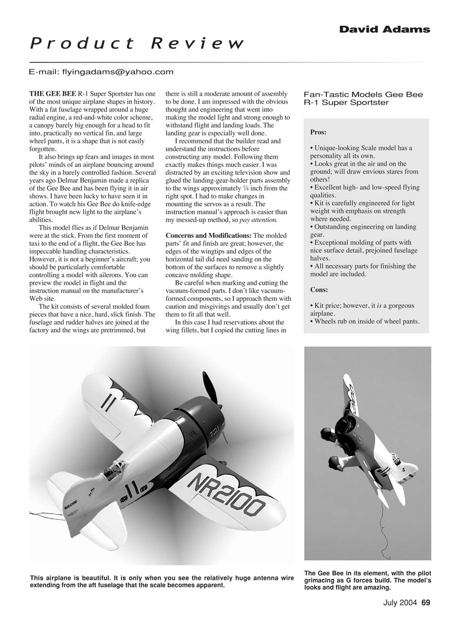
THE GEE BEE R-1 Super Sportster has one of the most unique airplane shapes in history. With a fat fuselage wrapped around a huge radial engine, a red-and-white color scheme, a canopy barely big enough for a head to fit into, practically no vertical fin, and large wheel pants, it is a shape that is not easily forgotten.
It also brings up fears and images in most pilots’ minds of an airplane bouncing around the sky in a barely controlled fashion. Several years ago Delmar Benjamin made a replica of the Gee Bee and has been flying it in air shows. I have been lucky to have seen it in action. To watch his Gee Bee do knife-edge flight brought new light to the airplane’s abilities.
This model flies as if Delmar Benjamin were at the stick. From the first moment of taxi to the end of a flight, the Gee Bee has impeccable handling characteristics. However, it is not a beginner’s aircraft; you should be particularly comfortable controlling a model with ailerons. You can preview the model in flight and view the instruction manual on the manufacturer’s Web site.
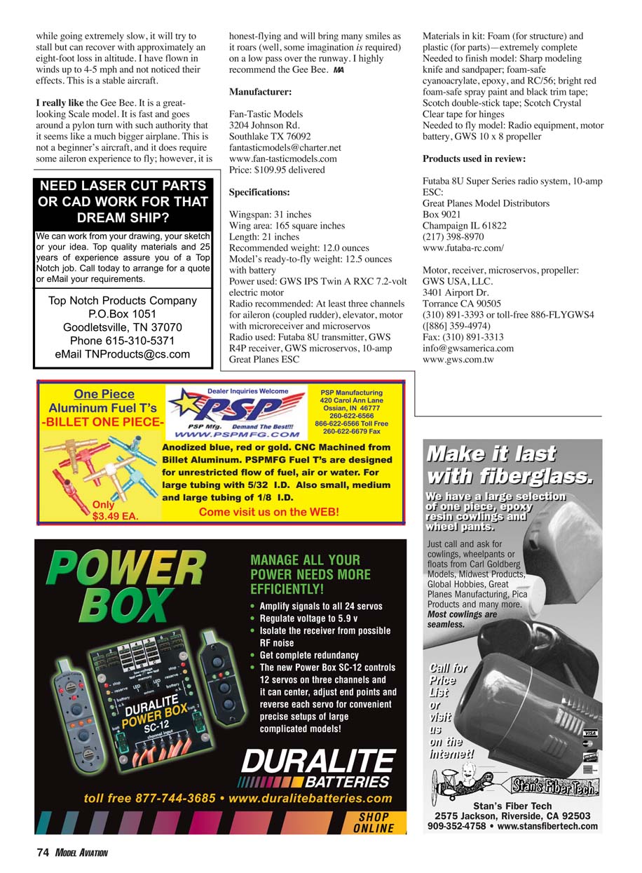
The kit consists of several molded foam pieces that have a nice, hard, slick finish. The fuselage and rudder halves are joined at the factory and the wings are pretrimmed, but there is still a moderate amount of assembly to be done. I am impressed with the obvious thought and engineering that went into making the model light and strong enough to withstand flight and landing loads. The landing gear is especially well done.
I recommend that the builder read and understand the instructions before constructing any model. Following them exactly makes things much easier. I was distracted by an exciting television show and glued the landing-gear-holder parts assembly to the wing approximately 1/4 inch from the right spot. I had to make changes in mounting the servos as a result. The instruction manual’s approach is easier than my messed-up method, so pay attention.
Concerns and Modifications
The molded parts’ fit and finish are great; however, the edges of the wingtips and the edges of the horizontal tail did need sanding on the bottom surfaces to remove a slightly concave molding shape.
Be careful when marking and cutting the vacuum-formed parts. I don’t like vacuum-formed components, so I approach them with caution and misgivings and usually don’t get them to fit all that well. In this case I had reservations about the wing fillets, but I copied the cutting lines in the instructions as closely as I could, including the odd shape on the front of the fillet. Later I learned that they were a perfect match to the fuselage and wing, and the funny shape wrapped around the wing leading edge perfectly.
Sanding a notch in the wing leading edge to accept a round spar was time consuming and tedious. Take your time and let the sandpaper, wrapped around a dowel, do the cutting for you. The spar fit nicely; it was slightly smaller than the wing thickness.
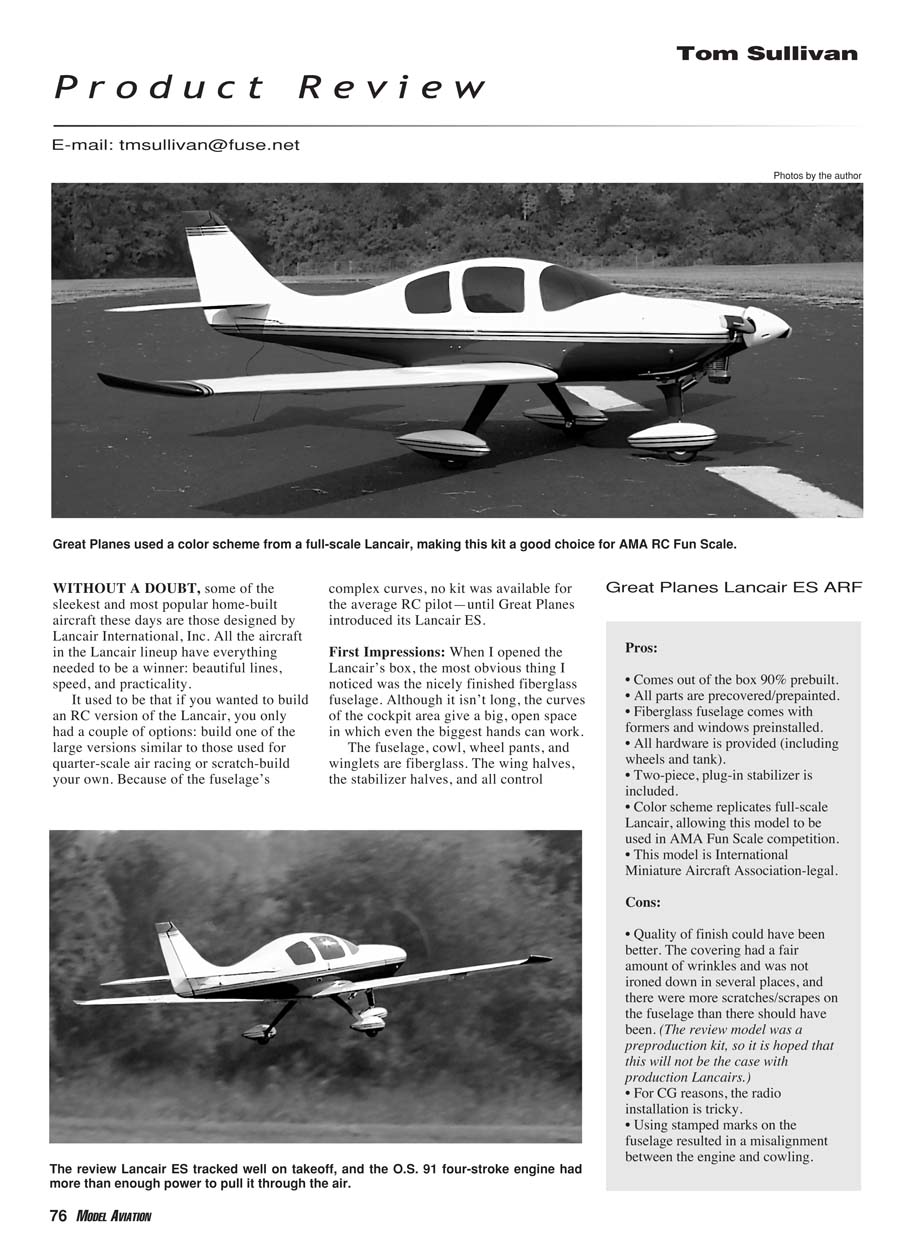
The landing gear is a unique structure that uses vacuum-formed parts and wire struts to form a rigid inner structure about which a decorative foam wheel pant is glued. The vacuum-formed parts have to be cut out so that each landing-gear leg gets a left and a right piece. A good way to see how much plastic to cut off is to place it in the foam wheel shell and remove any plastic that would prevent a smooth fit to the shell. You should make a mark on each part so after trimming they will be at the same place on both sides. The wheel assembly is strong and trouble free.
Do be careful making the landing gear, and make a left-wing and a right-wing assembly. It is easy to make two left-wing assemblies. (Don't ask.)
The provided wheels are too big for the space in the wheel pants. I mounted them in my Unimat and turned the rubber down slightly, keeping the basic shape the same. I did that until the wheels turned freely in the pants.
The rudder is hinged on one side by a molded-in foam hinge. The other side would have shown a big gap, but I carefully removed the foam by sanding until the rudder "nested" into the fuselage and vertical tail, and I installed a paper "gap cover." Take your time and this will look great.
As I mentioned earlier, I mislocated the landing-gear-holder parts when gluing them on the lower surface of the wing. As a result, I had to mount my servos differently. Instead of mounting them on a thin plywood plate as instructed, I had to mount the servos directly to the wing foam. This has not proven to be a problem, but it would have been easier if I had been more alert.
Notice that all radio gear is mounted to the wing, which is permanently glued to the fuselage. The wings are small enough compared to the fuselage that this is not a problem in transportation.
Paper painting masks are provided to help give the nice, curved red-paint edges. They are to be attached to the foam with double-stick tape to protect the unpainted white foam areas. The instructions note that some of the smooth surface might be removed if the tape is too tacky.
I used the painting masks as a guide to mark the paint lines on the foam and used regular masking tape to mask the edges. This worked well and protected the model's finish. I painted the wings, fuselage, wing fillets, landing-gear assemblies, and cowl separately before installation.
Radio Equipment
No radio equipment is provided. I used my Futaba 8U transmitter. To achieve the lightest weight, I used a GWS R4P receiver and GWS microservos. The ESC I had available was a Great Planes 10-amp unit. I also used eight-cell packs of 280 mAh NiMH batteries, which I had in the battery box, instead of the suggested NiCd packs.
Those substitutions have worked well, and my model is only 5 ounces heavier than the suggested weight. I plan on putting a dual-conversion receiver in the Gee Bee so I can fly it at my flying field without worrying about frequency conflicts.
Flying
Since this model is indoor/outdoor rated, I waited until we had a morning with an extremely light wind, as noted in the instruction manual. I had performed a thorough preflight of the airplane and checked control throws and CG location. I set the control throws per the instructions. My model's CG came out exactly where desired, with no additional weight needed.
Since I had watched the Gee Bee fly indoors on the Fan-Tastic Models Web site, I felt good about the upcoming flight but was still anxious because of tales I had heard about model Gee Bees. I taxied it around a bit, and the airplane seemed to be nicely responsive on the ground.
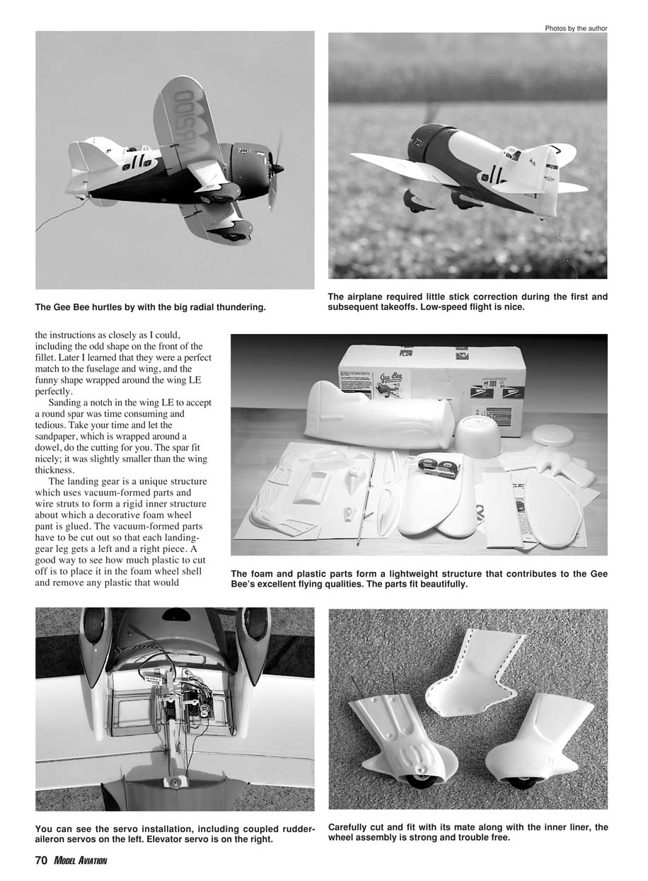
Pointing the model's nose into the wind, I slowly added power, ready to feed in rudder as needed. The Gee Bee tracked straight, and the tail came off the ground after a few feet. After roughly 20 feet, with a bit of up-elevator fed in, the airplane lifted off gently.
The climb rate was rapid since I wanted altitude on the first flight for trimming, and the Gee Bee was much faster than my Lite Stik airplanes. It needed a little up-elevator and right aileron trim to fly straight and level.
The airplane flew like a racing airplane, but with no bad tendencies. It was groovy and it looked great in the air when it came around in a racing turn. I tried a roll and was rewarded with a barrel roll. The loop I made was shaped better, but remember that this is not an aerobatic airplane.
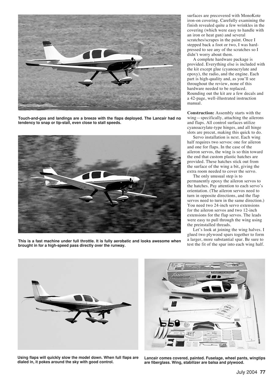
The model slowed nicely during the landing, responding to power settings and elevator and settling in as any other airplane would to a nice landing with the smallest bounce. Landings on grass are more of an arresting-hook type of landing; the Gee Bee does not roll on grass.
I have flown the airplane many times and have learned that if you try to maneuver it with quick, sudden moves it will protest at some point. Smooth control inputs work best and this will give you the best performance. The model is strong and has survived several heavy landings with no damage, except for a repair to the cowl after a noseover. When going extremely slow, it will try to stall but can recover with approximately an eight-foot loss in altitude. I have flown in winds up to 4–5 mph and not noticed their effects. This is a stable aircraft.
I really like the Gee Bee. It is a great-looking scale model. It is fast and goes around a pylon turn with such authority that it seems like a much bigger airplane. This is not a beginner’s aircraft, and it does require some aileron experience to fly; however, it is honest-flying and will bring many smiles as it roars (well, some imagination is required) on a low pass over the runway. I highly recommend the Gee Bee. MA
Manufacturer
Fan-Tastic Models 3204 Johnson Rd. Southlake, TX 76092 [email protected] www.fan-tasticmodels.com Price: $109.95 delivered
Specifications
- Wingspan: 31 inches
- Wing area: 165 square inches
- Length: 21 inches
- Recommended weight: 12.0 ounces
- Model’s ready-to-fly weight: 12.5 ounces with battery
- Power used: GWS IPS Twin A RXC 7.2-volt electric motor
- Radio recommended: At least three channels for aileron (coupled rudder), elevator, motor with microreceiver and microservos
- Radio used: Futaba 8U transmitter, GWS R4P receiver, GWS microservos, 10-amp Great Planes ESC
- Materials in kit: Foam (for structure) and plastic (for parts) — extremely complete
- Needed to finish model: Sharp modeling knife and sandpaper; foam-safe cyanoacrylate, epoxy, and RC/56; bright red foam-safe spray paint and black trim tape; Scotch double-stick tape; Scotch Crystal Clear tape for hinges
- Needed to fly model: Radio equipment, motor battery, GWS 10 x 8 propeller
Pros and Cons
Pros:
- Unique-looking scale model with a personality all its own.
- Looks great in the air and on the ground; will draw envious stares.
- Excellent high- and low-speed flying qualities.
- Kit is carefully engineered for light weight with emphasis on strength where needed.
- Outstanding engineering on landing gear.
- Exceptional molding of parts with nice surface detail and prejoined fuselage halves.
- All necessary parts for finishing the model are included.
Cons:
- Kit price; however, it is a gorgeous airplane.
- Wheels may rub on the inside of the wheel pants unless trimmed.
Products used in review
- Futaba 8U Super Series radio system; 10-amp ESC: Great Planes Model Distributors, Box 9021, Champaign, IL 61822, (217) 398-8970, www.futabarc.com
- Motor, receiver, microservos, propeller: GWS USA, LLC., 3401 Airport Dr., Torrance, CA 90505, (310) 891-3993 or toll-free 886-FLYGWS4 (886-359-4974), Fax: (310) 891-3313, [email protected], www.gws.com.tw
---
Great Planes Lancair ES
E-mail: [email protected]
Without a doubt, some of the sleekest and most popular home-built aircraft these days are those designed by Lancair International, Inc. All the aircraft in the Lancair lineup have everything needed to be a winner: beautiful lines, speed, and practicality.
It used to be that if you wanted to build an RC version of the Lancair, you only had a couple of options: build one of the large versions similar to those used for quarter-scale air racing or scratch-build your own. Because of the fuselage's complex curves, no kit was available for the average RC pilot—until Great Planes introduced its Lancair ES.
First Impressions
When I opened the Lancair's box, the most obvious thing I noticed was the nicely finished fiberglass fuselage. Although it isn't long, the curves of the cockpit area give a big, open space in which even the biggest hands can work.
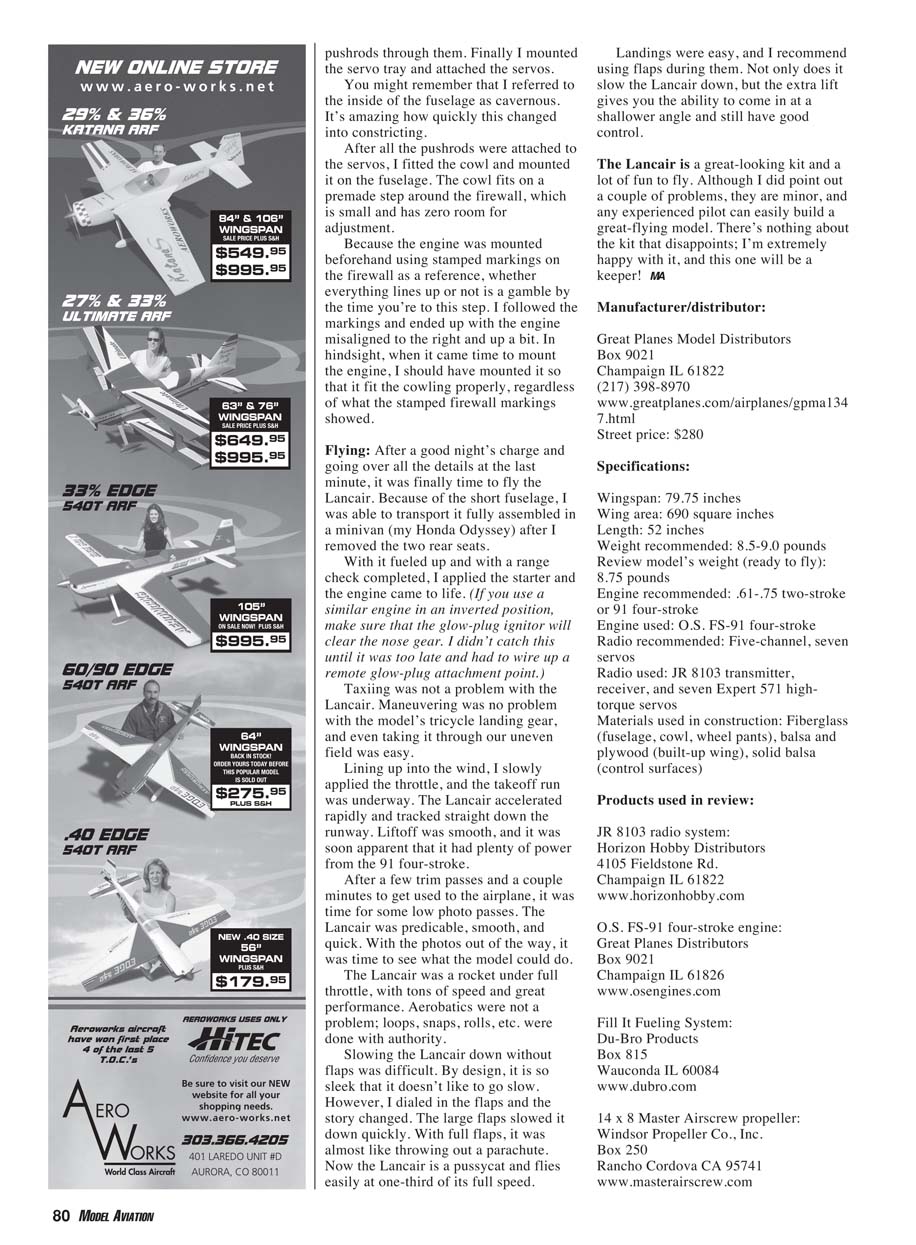
The fuselage, cowl, wheel pants, and winglets are fiberglass. The wing halves, stabilizer halves, and all control surfaces are foam. The surfaces are precovered with MonoKote iron-on covering. Carefully examining the finish revealed quite a few wrinkles in the covering (which were easy to handle with an iron or heat gun) and several scratches/scrapes in the paint. Once I stepped back a foot or two, I was hard-pressed to see any of the scratches so I didn't worry about them.
A complete hardware package is provided. Everything else is included with the kit except glue (cyanoacrylate and epoxy), the radio, and the engine. Each part is high-quality and, as you'll see throughout the review, none of the hardware needed to be replaced. Rounding out the kit are a few decals and a 42-page, well-illustrated instruction manual.
Construction
Assembly starts with the wing—specifically, attaching the ailerons and flaps. All control surfaces utilize cyanoacrylate-type hinges, and all hinge slots are precut, making this quick to do.
Servo installation is next. Each wing half requires two servos: one for aileron and one for flaps. In the case of the aileron servos, the wing is so thin toward the tip that custom plastic hatches are provided. These hatches stick out from the surface of the wing a bit, giving the extra room needed to cover the servo.
The only unusual step is to permanently epoxy the aileron servos to the hatches. Pay attention to each servo's orientation: the aileron servos need to turn in opposite directions, and the flap servos need to turn in the same direction. You need two 24-inch servo extensions for the aileron servos and two 12-inch extensions for the flap servos. The leads were easy to pull through the wing using the preinstalled threads.
Joining the wing halves required gluing two plywood spars together to form a larger, more substantial spar. Be sure to test the fit of the spar into each wing half. This kit required a bit of sanding, not only to allow the spar to be inserted, but to shorten it enough so that the wings mate properly. After the fit was right, I joined everything with 30-minute epoxy.
To finish the wings I added the control hardware, epoxied on the winglets, and glued on a plywood piece to stiffen the area around the wing-hold-down bolts.
The stabilizer can be built as a fixed unit or as removable halves; I chose the removable route. The stabilizer halves slide onto an aluminum tube and a carbon-fiber antirotation tube. I secured each half by drilling and tapping into the aluminum tube, and then fastening everything with two screws.
Attaching the rudder and elevator halves was done using the same cyanoacrylate-type hinge material used in the wing assembly. Again, all slots were precut, making this step quick.
Fuselage and Systems
The first step in the fuselage construction is to cut three holes toward the back where the pushrods exit. The manual mentions two ways: using progressively larger drill bits or using a small grinding bit with a Dremel-type rotary tool. I chose the drill-bit method at first but advise against it: the paint and fiberglass will chip using even the sharpest drill bit. The rotary tool method is cleaner.
To finish the wings I inserted the pushrod guide tubes through these holes, snaked them through the fuselage, and then cut the pushrods to length.
I installed the landing gear, which was straightforward. The two main gear attach to preinstalled hardwood plates on the bottom of the wing. The steerable nose gear is mounted in place with the supplied hardware, and then holes are drilled into the firewall for the steering pushrod (and the throttle pushrod). The manual had me attach the nose-wheel fairings, wheel, and wheel pants; in hindsight I would have preferred to attach those pieces before mounting the nose gear to the fuselage.
I chose to mount an O.S. FS-91 four-stroke engine. Regardless of how it's mounted, the 91's cylinder head will stick out of the cowl, so I mounted it inverted to hide it from view when the model is sitting in the pit area. (The manual shows installation of a .61 two-stroke with a Top Flite muffler; that installation does not require the cowl to be cut out but does require the bottom of the fuselage to be cut for a cooling duct. Either way, you will end up cutting something for proper engine cooling.)
To finish the power system I assembled the fuel tank and slid it into position. I like to use a three-line system and incorporated the Du-Bro Fill It Fueling System into the tank. With this setup, two of the lines were standard carburetor feeds (each with a clunk) and the third was used to fill and empty the tank.
Radio Installation and Final Fit
Radio installation turned out to be less straightforward than expected. The Lancair's short fuselage means that weight distribution is key to getting the correct CG balance. To do this, Great Planes has chosen some unique steps.
The battery and receiver are attached to a plywood tray subassembly with rubber bands. This subassembly slides into position under the pushrods and is held in place by a couple of screws. Then you plug in all the servos, extensions, and Y harnesses. Two formers go in the front and rear of the saddle area; feed the pushrods through them. Finally mount the servo tray and attach the servos.
The inside of the fuselage initially seems cavernous, but it quickly becomes constricting once everything is in place. After the pushrods were attached to the servos, I fitted the cowl and mounted it on the fuselage. The cowl fits on a premade step around the firewall, which is small and has zero room for adjustment.
Because the engine was mounted beforehand using stamped markings on the firewall as a reference, whether everything lines up or not is a gamble by the time you reach this step. I followed the markings and ended up with the engine misaligned to the right and up a bit. In hindsight, when it came time to mount the engine, I should have mounted it so that it fit the cowling properly, regardless of what the stamped firewall markings showed.
Summary
The Lancair ES kit presents a nice balance of high-quality fiberglass parts and foam wing/stab components. The hardware package is complete and well thought out. Be prepared for careful fitting around the firewall and cowl, attention to servo orientation and extensions, and planning for CG placement. The instructions are generally good and the precut hinge slots speed assembly, but some fiberglass and paint finish work may be necessary.
Manufacturer
Great Planes (Lancair ES kit) — contact via Great Planes retailers and distributors.
(End of reformatted reviews.)
Transcribed from original scans by AI. Minor OCR errors may remain.

