

Product Review
Steve Kaluf
E-mail: [email protected]
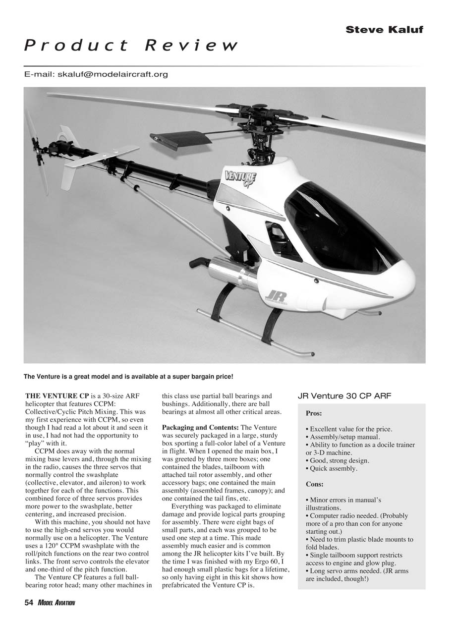
THE VENTURE CP is a 30-size ARF helicopter that features CCPM: Collective/Cyclic Pitch Mixing. This was my first experience with CCPM, so even though I had read a lot about it and seen it in use, I had not had the opportunity to "play" with it.
CCPM does away with the normal mixing base levers and, through the mixing in the radio, causes the three servos that normally control the swashplate (collective, elevator, and aileron) to work together for each of the functions. This combined force of three servos provides more power to the swashplate, better centering, and increased precision.
With this machine, you should not have to use the high-end servos you would normally use on a helicopter. The Venture uses a 120° CCPM swashplate with the roll/pitch functions on the rear two control links. The front servo controls the elevator and one-third of the pitch function. The Venture CP features a full ball-bearing rotor head; many other machines in this class use partial ball bearings and bushings. Additionally, there are ball bearings at almost all other critical areas.
Packaging and Contents
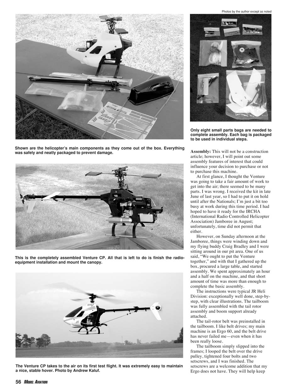
The Venture was securely packaged in a large, sturdy box sporting a full-color label of a Venture in flight. When I opened the main box, I was greeted by three more boxes: one contained the blades, tailboom with attached tail rotor assembly, and other accessory bags; one contained the main assembly (assembled frames, canopy); and one contained the tail fins, etc. Everything was packaged to eliminate damage and provide logical parts grouping for assembly. There were eight bags of small parts, and each was grouped to be used one step at a time. This made assembly much easier and is common among the JR helicopter kits I've built. By the time I was finished with my Ergo 60, I had enough small plastic bags for a lifetime, so only having eight in this kit shows how prefabricated the Venture CP is.
Assembly
This will not be a construction article; however, I will point out some assembly features of interest that could influence your decision to purchase or not to purchase this machine.
At first glance, I thought the Venture was going to take a fair amount of work to get into the air; there seemed to be many parts. I was wrong. I received the kit in late June of last year, so I had to put it on hold until after the Nationals; I'm just a bit too busy at work during that time period. I had hoped to have it ready for the IRCHA Jamboree in August; unfortunately, time did not permit that either. However, on Sunday afternoon at the Jamboree, things were winding down and my flying buddy Craig Bradley and I were sitting around in our pit area. One of us said, "We ought to put the Venture together," and with that I gathered up the box, procured a large table, and started assembly. We spent approximately an hour and a half on the machine, and that short amount of time was more than enough to complete the basic assembly. The instructions were typical JR Heli Division: exceptionally well done, step-by-step, with clear illustrations.
The tailboom was fully assembled with the tail rotor assembly and boom support already attached. The tail-rotor belt was preinstalled in the tailboom. I like belt drives; my main machine is an Ergo 60, and the belt drive has never failed me—even when it has been really loose. The tailboom simply slipped into the frames; I looped the belt over the drive pulley, tightened four bolts and two setscrews, and I was finished. The setscrews are a welcome addition. They will help keep the boom from slipping and the belt tight. With the simple addition of the tailboom, the Venture suddenly looked like a helicopter.
When installing the long control rod for the rotor pitch, be sure to space the rod supports on the boom as shown in the instructions and position them to give the rod the smoothest flow and movement between the tail-rotor link and the servo. Do this check before hooking the links up to the servo or tail-rotor control arm, and adjust until it is as good as it can be.
Engine/clutch/fan installation was next. During the first few days of the Jamboree I looked around for an engine and pipe for the Venture. I was going to choose the Thunder Tiger .39, the Webra .35, or the O.S. Max .32. I talked to many people and got almost as many opinions on which to use. I finally settled on the O.S. .32.
Ron Lund from Rick’s / R/C Helicopters gave me a good price and further enticed me with a just-delivered Curtis Youngblood Enterprises Muscle Pipe II. This is a new pipe for the 30-class engines. It looks like I got one of the first ones. One of the great things about the Jamboree is that almost everyone who is anyone in helicopters is there, including Curtis. He was happy to talk to me about the new pipe.
The engine mount supplied with the Venture was a plastic-type material that appeared to be the same material used for the frames and other plastic parts. This seemed to be a super-strong material. The mount’s holes were offset to accommodate Webra and O.S. engines. For one you turn the mount in one direction, and for the other you turn the mount in the other direction. I suspect that the mount would also accommodate the Thunder Tiger .39; I know of people using that engine in the Venture. All mounting hardware was supplied.
Once the mount was on the O.S., I installed the clutch/fan assembly on the engine. This assembly mounted right on what would be the propeller drive boss, so be sure your engine has this included; the O.S. does. Be sure to use thread lock everywhere the manual directs you to. I put a dial indicator on the clutch and was quite happy to find that the runout was minimal—excellent, in fact.
The Venture’s frames were strong and not flat as you’d normally find on a helicopter kit. They were molded and bolted together, so there were no standoffs as you’d normally find. JR calls this a box frame system. I feel that the Venture would have outstanding crash survivability.
The engine with mounted fan/clutch slipped in between the frames with the engine cylinder facing the rear. I lined up the bottom of the clutch with the bottom of the clutch bell and checked around the sides to make sure the clutch was not misaligned. Everything seemed to line up perfectly. I also checked the gear lash between the main and drive gears using a thin piece of paper. It, too, seemed perfect.
The engine mount had slots into which aircraft nuts could be inserted. The bolts had large finish-type washers that spread the load on the frames. This made engine installation incredibly easy.
The only real criticism I have of this machine is the single tailboom support. Don’t get me wrong; it was plenty strong. However, the support tended to block access to the glow plug. I did not install a plug before I installed the engine, and even though I have a long glow-plug wrench, I could not install the plug without removing the boom support from the attachment point on the rear of the frames. This may not be a big bother in normal operation, but it could be a real problem if you were in a contest; the clock would tick away while you tried to get a new plug in. The frames seemed to have attachment points for a dual boom support, so perhaps JR has already recognized this setback.
The servo installation was next. This is important, and you must have the servos installed and the output arms centered to install the linkages. The manual provided good illustrations of how the servos and output arms were to be oriented. Be sure to follow this carefully; it is critical for the proper setup of the machine.
There were a couple discrepancies in the illustrations for the left-side front servo. The first illustrations showed it correctly oriented on its side, and later ones showed it on end. This was obviously incorrect because the mount was actually sideways in the frame. Screws and washers were supplied to properly mount the servos. One side of each of the mounts moved a little to accommodate the slightly different servo sizes. Make sure that you insert the mounting screws into the holes in the mount—not between the mount and the frame. A good light is necessary to see in the frame and confirm that everything is right.
The linkages were preassembled, and the manual showed the exact length to which each should be set. I set each linkage to the proper length and made sure the arms were oriented correctly. I was rewarded with a level swashplate the first time I turned on the radio! I also found the CCPM setup to be easier; there were fewer bellcranks and levers to worry about keeping 90° to this or that and to line up.
One of the last things you do is cut out the windshield for the canopy (which fortunately is ready to go). I don't enjoy cutting out windshields—probably because I'm not very good at it. The best advice I can give you is to use a good, sharp pair of scissors with fairly short blades. The special ones made for cutting out RC car bodies work the best. Long blades will not take the curves sharp enough.
The windshield had cutting guidelines, so this one was not too bad to cut out. I like to cut a little wide of the markings so I can use sandpaper to smooth the cuts down to the line; that also radiuses the curves nicely. According to the manual, the windshield is held in place with six sheet-metal screws; however, only five were supplied.
This was the first ARF helicopter I had ever assembled. I had a few concerns about ARFs in general, one of which was the quality of the machine's preassembly. Would I find critical bolts or screws that were loose? To eliminate those worries, I went through every bolt, nut, and screw on the Venture to make sure everything was properly tight. I'm happy to report that I did not find a single loose fastener.
Another concern I've always had was about the knowledge lost by not assembling the entire machine—not having the full assembly instructions. The Venture's manual took care of at least part of that by supplying complete assembly instructions for all the preassembled components. The manual also had exploded views for the entire machine. So if I ever have to take my Venture completely apart, I will have complete assembly instructions if I need them. This is a great feature.
The Venture had a low parts count, which is an advantage from a couple of perspectives. The main advantage is that the fewer parts there are, the less complicated the machine tends to be. And the less complicated the machine, the easier it is to properly maintain. The Venture CP is sure to be easy to maintain indeed.
Radio setup would have been well documented in the manual if I had a JR; the instructions provided exact settings for all helicopter systems the company manufactures. If you use a different brand, as I did, the instructions still provide you with most of what you need to make the initial setup simple. Just pick the radio-setup instructions that match your system the closest.
I started out setting the servo reversing to what the manual recommended; that is not always right, but it gets you close. With CCPM, you also need to set up your radio for the CCPM swashplate. Most current systems have this preprogrammed in; be sure to select the correct one. My Futaba 9C's manual was good at explaining this and had a chart to help troubleshoot the setup.
Flight Test
Once everything was going in the right direction and checked again, it was time for the first test flight. I chose to leave the canopy off for the first quick flight so I could see all the linkages and to allow the engine as much cooling as possible.
The O.S. .32 fired as soon as the fuel had made it into the carburetor. The engine was set purposely rich for break-in. I slowly advanced the throttle, but the engine was a bit too rich to take off. I leaned it roughly a half turn and tried again. That time the blades spooled up fine.
I could tell right away that the pitch curve was a bit low and the throttle curve was a bit high. However, advancing the throttle to slightly less than three-quarters lifted the Venture off. This initial hover at approximately a foot off the ground was almost hands off. I let the engine run there for roughly a half tank, and then I landed the model and shut it down to cool off, and I checked all the mechanics.
The engine and mechanics looked good. I made adjustments to the pitch and throttle curves to get everything more to my liking for hovering. Not having worked with a 30-size machine before, I was unprepared for what sounded like the engine revving fairly high. The Muscle Pipe was also a bit louder than I expected. Curtis told me that you can use a wire tie to constrict the exhaust diverter and make the pipe quieter without losing performance, but I haven't tried that yet. I was greatly impressed by the amount of available power the engine/pipe package delivered. Curtis also told me to resist the temptation to lean the engine out with this pipe. I like to run a little on the rich side anyway, so that was almost welcome news to me.
I installed the canopy and fired up for another test flight. The pitch curve was much better, although I still felt that the engine was turning up higher than it needed to. The machine was stable in the hover—much more so than I expected for a 30-size machine. The controls were crisp.
Over the course of the next four tanks of fuel, I could feel the engine getting better and better. I slowly leaned the high end and finally the low end just a bit. The throttle response was instantaneous, and the engine/pipe combination pulled very strong. I also pulled the throttle curve down a bit more.
The machine is stable in the hover at a head speed of 1,520–1,540 rpm. I've had it as low as 1,350 with no wobble at all, although it is tough to maintain a steady altitude at that rpm. Flying some slow-to-medium-speed circuits (in the normal flight condition) showed that the head speed remained fairly steady. The Venture is smooth at these speeds; the tail seems to have plenty of authority.
I also feel that dialing in the pitch and throttle curves has been easier than on my Ergo. Even though the Ergo is great, there are times when I still feel as though I'm chasing the curves a bit. That does not seem to be the case with the Venture so far. I don't know for sure if it is because of the CCPM setup or the new parts, but whatever it is works.
The Venture has another unique feature; it came with two flybars, two sets of paddles, and paddle weights. The paddles that are installed on the machine are what the novice helicopter pilot would use. The kit also included weights that slipped inside the paddles. These, for some reason, were not mentioned in the instructions except in the back of the manual where it showed how to assemble the preassembled parts.
The "stock" paddles are not overly sensitive without these weights, so I'm not sure you would want to install them. However, if you needed to calm things down a bit, I'm sure that installing the weights would be a good starting point because they do slow the response somewhat.
The second flybar and paddles are for 3-D. I'm not a 3-D pilot, so I can't give you a full report, but installing this flybar/paddle combination does liven it up quite a bit. There is a great deal of control authority available. I'm also extraordinarily impressed that with sport, non-ball-bearing servos, the controls are crisp and have terrific precision. I've watched Ventures do many extreme 3-D maneuvers, so I know they are more than capable—even if I’m not.
The wooden blades included seem pretty good. They balanced with only a small piece of tape on one blade. They performed well in the hover, and they worked well doing circuits, maintaining head speed well while flying around. The blades do seem to slow down fairly fast in a low-level autorotation, but I still have enough collective left from as high as 15 feet to get down safely with only a gentle bounce.
Final Impressions
I like it! The Venture is generally available for roughly $269 at most hobby shops and almost everywhere I checked online. The parts are inexpensive (and readily available); a tailboom is $11.39, a main shaft is $8.99, a flybar is $9.50, main blades are $26.99, and tail rotor blades are $9.98. I put $190 into the engine and pipe. The servos are an inexpensive sport type.
So for approximately $500 you can have a top-notch model that is ready to go. But the Venture is much more than an inexpensive, easy-to-assemble helicopter; it is a capable machine that is a lot of fun to fly.
In the short time I’ve had the Venture, I’ve found myself trying things I’ve done before. It tends to inspire confidence and experimentation. I don’t know if it’s because of the lower cost investment or not, but I feel that it is because it flies so well.
I will be upgrading the tail rotor’s servo; the slower sport servo lags behind the gyro rather quickly. The Venture is a super entry-level machine, but it should not be overlooked by those who want a nimble 30-size machine. It will do it all.
JR Venture 30 CP ARF — Pros and Cons
Pros:
- Excellent value for the price.
- Assembly/setup manual.
- Ability to function as a docile trainer or a 3-D machine.
- Good, strong design.
- Quick assembly.
Cons:
- Minor errors in manual illustrations.
- Computer radio needed. (Probably more of a pro than a con for anyone starting out.)
- Need to trim plastic blade mounts to fold blades.
- Single tailboom support restricts access to engine and glow plug.
- Long servo arms needed. (JR arms are included, though!)
Specifications
- Rotor diameter: 49.5 inches
- Tail-rotor diameter: 9.3 inches
- Gear ratio: 9.78:1; 5.18:1
- Overall length: 44.6 inches
- Height: 17.2 inches
- Weight as tested: 7 pounds, 2 ounces (with 1800 mAh battery)
Distributor
Horizon Hobby 4105 Fieldstone Rd. Champaign, IL 61822 (217) 352-1913 (800) 338-4639 Fax: (217) 352-6799 www.horizonhobby.com
Other products used in review
Futaba 9CHP radio, GY401 gyroscope: Tower Hobbies Box 9078 Champaign, IL 61826 (217) 398-3636 (800) 637-6050 www.towerhobbies.com E-mail: [email protected]
---
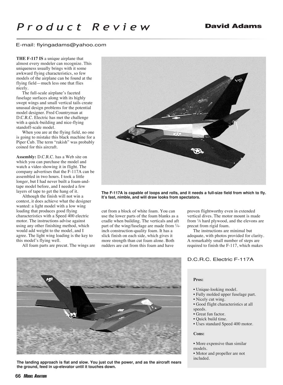
THE F-117 IS a unique airplane that almost every modeler can recognize. This uniqueness usually brings with it some awkward flying characteristics, so few models of the airplane can be found at the flying field — much less one that flies nicely.
The full-scale airplane's faceted fuselage surfaces along with its highly swept wings and small vertical tails create unusual design problems for the potential model designer. Fred Countryman at D.C.R.C. Electric has met the challenge with a quick-building and nice-flying standoff-scale model.
When you are at the flying field, no one is going to mistake this black machine for a Piper Cub. The term "rakish" was probably coined for this aircraft.
D.C.R.C. Electric F-117A
Assembly
D.C.R.C. has a Web site on which you can purchase the model and watch a video showing it in flight. The company advertises that the F-117A can be assembled in two hours. I took a little longer, but I had never built a foam-and-tape model before, and I needed a few layers of tape to get the hang of it.
Although the finish will not win a contest, it does achieve what the designer wanted: a light model with a low wing loading that produces good flying characteristics with a Speed 400 electric motor. The instructions advise against using any other finishing method, which would add weight to the model, and I agree. The light wing loading is the key to this model's flying well.
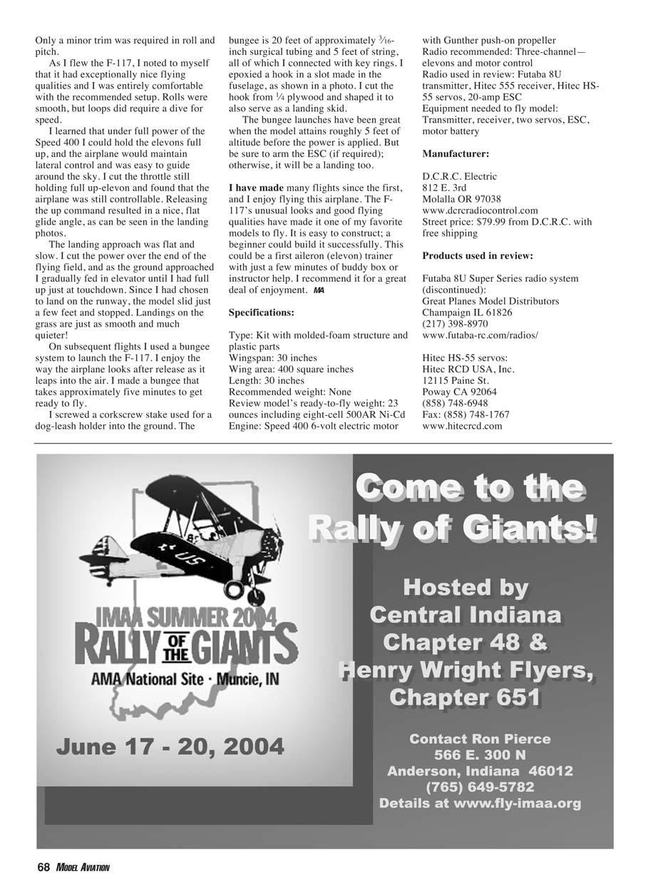
All foam parts are precut. The wings are cut from a block of white foam. You can use the lower parts of the foam blanks as a cradle when building. The verticals and aft part of the wing/fuselage are made from 1/4-inch construction-quality foam. It has a slick finish on each side, which gives it more strength than cut foam alone. Both rudders are cut from this foam and have proven flightworthy even in extended vertical dives. The motor mount is made from 1/8-inch hard plywood, and the elevons are precut from rigid foam.
The instructions are minimal but adequate, with photos provided for clarity. A remarkably small number of steps are required to finish the F-117, which makes it a quick build.
Do pay attention to the angle at which the vertical tails are set. There is a foam piece to set the angle, but apparently some builders have managed to angle the tails inward—not outward as they should be.
The preformed plastic upper fuselage surface gives shape with light weight and incorporates the delightful angles typical of the F-117. The upper fuselage surface is held on with hook-and-loop fastener tape and is removable for easy access to batteries and radio gear.
I added the sticky-backed decals to the model, including the nice gold-tinted windshield. There are no tricky or unusual steps required to make the model, and even a beginner could build it successfully.
Equipment
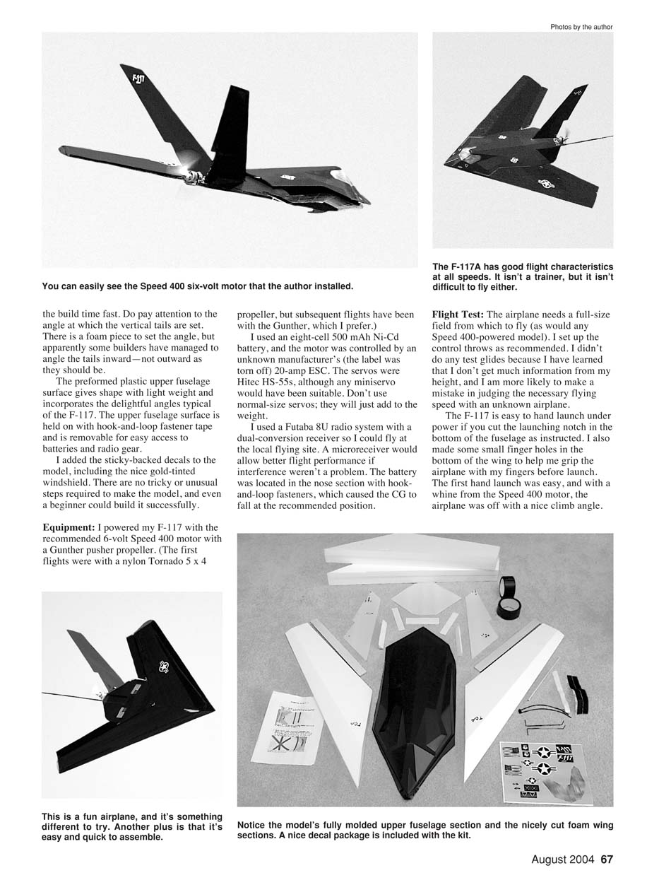
I powered my F-117 with the recommended 6-volt Speed 400 motor with a Gunther pusher propeller. (The first flights were with a nylon Tornado 5 x 4 propeller, but subsequent flights have been with the Gunther, which I prefer.)
I used an eight-cell 500 mAh Ni-Cd battery, and the motor was controlled by an unknown manufacturer's 20-amp ESC (the label was torn off). The servos were Hitec HS-55s, although any miniservo would have been suitable. Don't use normal-size servos; they will just add to the weight.
I used a Futaba 8U radio system with a dual-conversion receiver so I could fly at the local flying site. A microreceiver would allow better flight performance if interference weren't a problem. The battery was located in the nose section with hook-and-loop fasteners, which caused the CG to fall at the recommended position.
Flight Test
The airplane needs a full-size field from which to fly (as would any Speed 400-powered model). I set up the control throws as recommended. I didn't do any test glides because I have learned that I don't get much information from my height, and I am more likely to make a mistake in judging the necessary flying speed with an unknown airplane.
The F-117 is easy to hand launch under power if you cut the launching notch in the bottom of the fuselage as instructed. I also made some small finger holes in the bottom of the wing to help me grip the airplane with my fingers before launch. The first hand launch was easy, and with a whine from the Speed 400 motor, the airplane was off with a nice climb angle. Only a minor trim was required in roll and pitch.
As I flew the F-117, I noted that it had exceptionally nice flying qualities and I was entirely comfortable with the recommended setup. Rolls were smooth, but loops did require a dive for speed.
I learned that under full power of the Speed 400 I could hold the elevons full up, and the airplane would maintain lateral control and was easy to guide around the sky. I cut the throttle still holding full up-elevon and found that the airplane was still controllable. Releasing the up command resulted in a nice, flat glide angle, as can be seen in the landing photos.
The landing approach was flat and slow. I cut the power over the end of the flying field, and as the ground approached I gradually fed in elevator until I had full up just at touchdown. Since I had chosen to land on the runway, the model slid just a few feet and stopped. Landings on the grass are just as smooth and much quieter!
On subsequent flights I used a bungee system to launch the F-117. I enjoy the way the airplane looks after release as it leaps into the air. I made a bungee that takes approximately five minutes to get ready to fly.
I screwed a corkscrew stake used for a dog-leash holder into the ground. The bungee is 20 feet of approximately 3/16-inch surgical tubing and 5 feet of string, all of which I connected with key rings. I epoxied a hook in a slot made in the fuselage, as shown in a photo. I cut the hook from 1/4-inch plywood and shaped it to also serve as a landing skid.
The bungee launches have been great when the model attains roughly 5 feet of altitude before the power is applied. But be sure to arm the ESC (if required); otherwise, it will be a landing too.
I have made many flights since the first, and I enjoy flying this airplane. The F-117's unusual looks and good flying qualities have made it one of my favorite models to fly. It is easy to construct; a beginner could build it successfully. This could be a first aileron (elevon) trainer with just a few minutes of buddy-box or instructor help. I recommend it for a great deal of enjoyment.
Final Impressions
The F-117 is a unique, fun-to-fly model that builds quickly and flies well on modest power. It’s lightweight, has forgiving flight characteristics, and is suitable for beginners who want an interesting aileron trainer or for experienced pilots looking for a quick, fun sport model.
Specifications
- Type: Kit with molded-foam structure and plastic parts
- Wingspan: 30 inches
- Wing area: 400 square inches
- Length: 30 inches
- Recommended weight: None specified
- Review model's ready-to-fly weight: 23 ounces (including eight-cell 500 mAh Ni-Cd)
- Engine: Speed 400 6-volt electric motor with Gunther push-on propeller
- Radio recommended: Three-channel—elevons and motor control
- Radio used in review: Futaba 8U transmitter, Hitec 555 receiver, Hitec HS-55 servos, 20-amp ESC
- Equipment needed to fly model: Transmitter, receiver, two servos, ESC, motor, battery
Manufacturer
D.C.R.C. Electric 812 E. 3rd Molalla, OR 97038 www.dcrcradiocontrol.com Street price: $79.99 from D.C.R.C. with free shipping
Products used in review
Futaba 8U Super Series radio system (discontinued): Great Planes Model Distributors Champaign, IL 61826 (217) 398-8970 www.futaba-rc.com/radios/
Hitec HS-55 servos: Hitec RCD USA, Inc. 12115 Paine St. Poway, CA 92064 (858) 748-6948 Fax: (858) 748-1767 www.hitecrcd.com
Transcribed from original scans by AI. Minor OCR errors may remain.

