
Extreme Flight RC Edge 540T ARF
Dennis Ridenhour E-mail: [email protected]
ARE YOU ITCHING to try some of this new 3-D stuff? Maybe see if you have the "right stuff" to hover, Harrier, etc.? I did, and I decided to take on this review of the Extreme Flight Radio Control Edge 540T Profile ARF. What a mouthful!
The Edge is one of the latest designs, geared to be a 3-D trainer. It is meant to be inexpensive and quick to assemble and use. It supplies a platform on which you can polish your skills before moving on to bigger, more extravagant models.
First Impressions
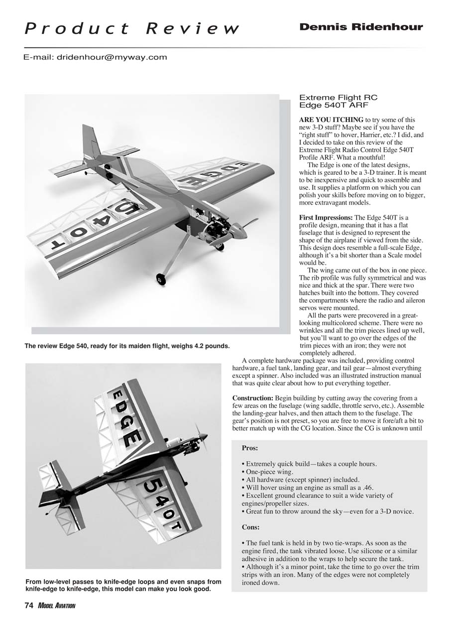
The Edge 540T is a profile design, meaning that it has a flat fuselage that is designed to represent the shape of the airplane if viewed from the side. This design does resemble a full-scale Edge, although it's a bit shorter than a scale model would be.
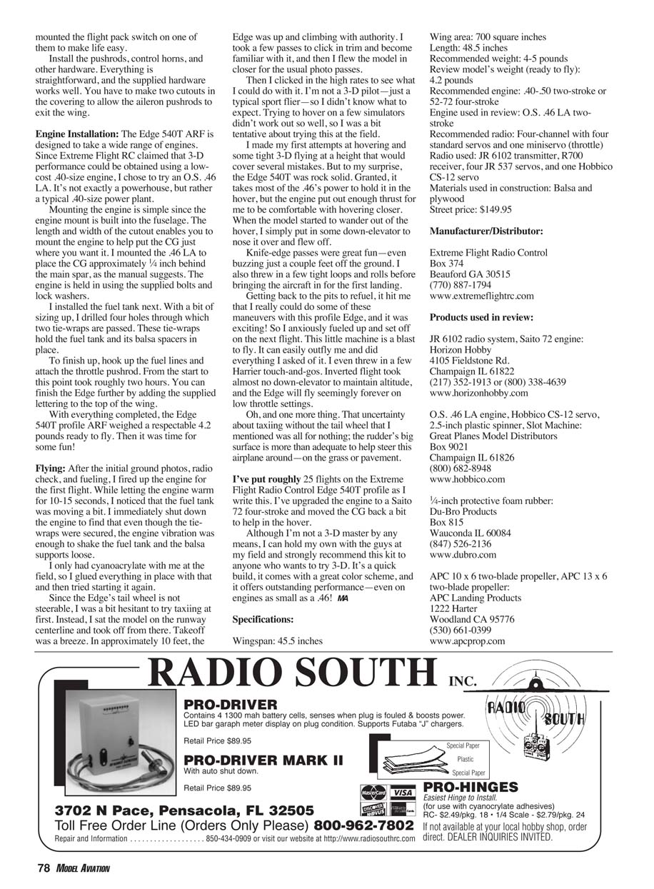
The wing came out of the box in one piece. The rib profile was fully symmetrical and nice and thick at the spar. There were two hatches built into the bottom that covered the compartments where the radio and aileron servos were mounted.
All the parts were precovered in a great-looking multicolored scheme. There were no wrinkles and all the trim pieces lined up well, but you'll want to go over the edges of the trim pieces with an iron; they were not completely adhered.
A complete hardware package was included, providing control hardware, a fuel tank, landing gear, and tail gear—almost everything except a spinner. Also included was an illustrated instruction manual that was quite clear about how to put everything together.
Construction
Begin building by cutting away the covering from a few areas on the fuselage (wing saddle, throttle servo, etc.). Assemble the landing-gear halves, and then attach them to the fuselage. The gear's position is not preset, so you are free to move it fore/aft a bit to better match up with the CG location. Since the CG is unknown until the model is almost finished, in hindsight I would have left this step until later.
Attach the tail wheel, wing, and horizontal stabilizer. There's nothing out of the ordinary here; just make sure everything is straight and true. After the glue has cured, attach the movable surfaces. You will have to cut slots for the hinges; I used Great Planes' Slot Machine to help speed this step along. Because the hinge material is the type that is attached with cyanoacrylate glue, adhering the surfaces was fairly quick and painless.
Radio Installation
The basic airframe is complete at this point. Begin radio installation by mounting the servos in their various locations. The elevator and rudder servos are mounted just forward of the horizontal stabilizer. This gives a short, slop-free linkage to the surfaces. However, it does require that you use two 24-inch servo extensions to connect to the receiver. A nice touch is that a channel is built into the bottom of the fuselage where you can route the extensions. Once the wires are in place, they are covered by a supplied piece of matching iron-on film.
The receiver and battery are mounted in separate compartments in the wing. Each compartment has a panel that covers it, and I mounted the power switch on one hatch door to simplify things.
Install the pushrods, control horns, and other hardware. Everything is straightforward, and the supplied hardware works well. You have to make two cutouts in the covering to allow the aileron pushrods to exit the wing.
Pros
- Extremely quick build—takes a couple hours.
- One-piece wing.
- All hardware (except spinner) included.
- Will hover using an engine as small as a .46.
- Excellent ground clearance to suit a wide variety of engines/propeller sizes.
- Great fun to throw around the sky—even for a 3-D novice.
Cons
- The fuel tank is held in by two tie-wraps. As soon as the engine fired, the tank vibrated loose. Use silicone or a similar adhesive in addition to the wraps to help secure the tank.
- Although it's a minor point, take the time to go over the trim strips with an iron. Many of the edges were not completely ironed down.
Engine Installation
The Edge 540T ARF is designed to take a wide range of engines. Since Extreme Flight RC claimed that 3-D performance could be obtained using a low-cost .40-size engine, I chose to try an O.S. .46 LA. It's not exactly a powerhouse, but rather a typical .40-size power plant.
Mounting the engine is simple since the engine mount is built into the fuselage. The length and width of the cutout enable you to mount the engine just where you want it. I mounted the .46 LA to place the CG approximately 1/4 inch behind the main spar, as the manual suggests. The engine is held in using the supplied bolts and lock washers.
I installed the fuel tank next. With a bit of sizing up, I drilled four holes through which two tie-wraps are passed. These tie-wraps hold the fuel tank and its balsa spacers in place. To finish up, hook up the fuel lines and attach the throttle pushrod. From the start to this point took roughly two hours. You can finish the Edge further by adding the supplied lettering to the top of the wing.
With everything completed, the Edge 540T profile ARF weighed a respectable 4.2 pounds ready to fly.
Flying
After the initial ground photos, radio check, and fueling, I fired up the engine for the first flight. While letting the engine warm for 10–15 seconds, I noticed that the fuel tank was moving a bit. I immediately shut down the engine to find that even though the tie-wraps were secured, the engine vibration was enough to shake the fuel tank and the balsa supports loose.
I only had cyanoacrylate with me at the field, so I glued everything in place with that and then tried starting it again.
Since the Edge's tail wheel is not steerable, I was a bit hesitant to try taxiing at first. Instead, I sat the model on the runway centerline and took off from there. Takeoff was a breeze. In approximately 10 feet, the Edge was up and climbing with authority. I took a few passes to click in trim and become familiar with it, and then I flew the model in closer for the usual photo passes.
Then I clicked in the high rates to see what I could do with it. I'm not a 3-D pilot—just a typical sport flier—so I didn't know what to expect. Trying to hover on a few simulated 3-D maneuvers didn't work out so well, so I was a bit tentative about trying this at the field.
I made my first attempts at hovering and some tight 3-D flying at a height that would cover several mistakes. But to my surprise, the Edge 540T was rock solid. Granted, it takes most of the .46's power to hold it in the hover, but the engine put out enough thrust for me to be comfortable with hovering closer.
When the model started to wander out of the hover, I simply put in some down-elevator to nose it over and flew off.
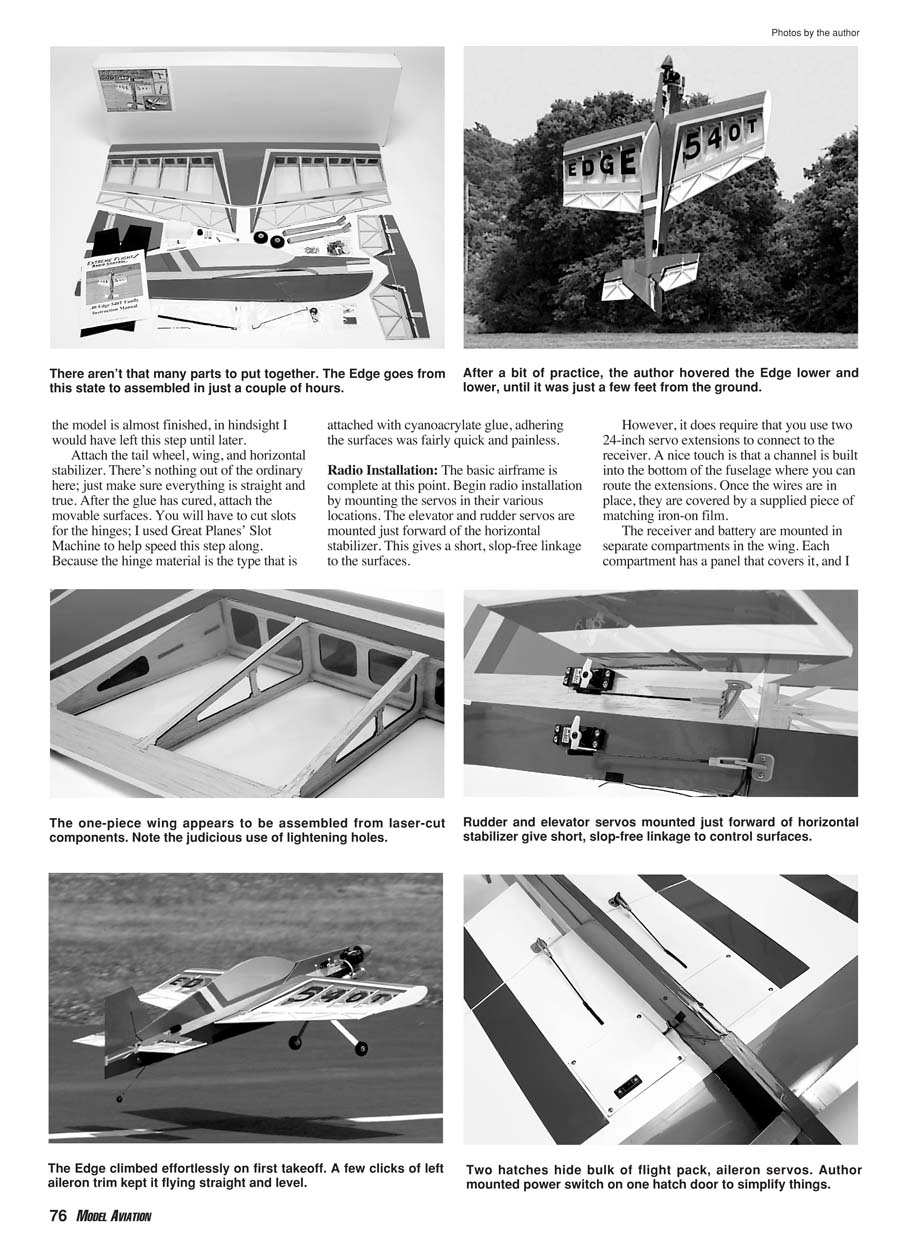
Knife-edge passes were great fun—even buzzing just a couple feet off the ground. I also threw in a few tight loops and rolls before bringing the aircraft in for the first landing.
Getting back to the pits to refuel, it hit me that I really could do some of these maneuvers with this profile Edge, and it was exciting! I anxiously fueled up and set off on the next flight. This little machine is a blast to fly. It can easily outfly me and did everything I asked of it. I even threw in a few Harrier touch-and-go's. Inverted flight took almost no down-elevator to maintain altitude, and the Edge will fly seemingly forever on low throttle settings.
One more thing: the rudder's large surface is more than adequate to help steer this airplane on grass or pavement, so my earlier taxi concerns were unfounded.
I've put roughly 25 flights on the Extreme Flight Radio Control Edge 540T profile as I write this. I've upgraded the engine to a Saito 72 four-stroke and moved the CG back a bit to help in the hover.
Although I'm not a 3-D master by any means, I can hold my own with the guys at my field and strongly recommend this kit to anyone who wants to try 3-D. It's a quick build, it comes with a great color scheme, and it offers outstanding performance—even on engines as small as a .46!
Specifications
- Wingspan: 45.5 inches
- Wing area: 700 square inches
- Length: 48.5 inches
- Recommended weight: 4–5 pounds
- Review model's weight (ready to fly): 4.2 pounds
- Recommended engine: .40–.50 two-stroke or 52–72 four-stroke
- Engine used in review: O.S. .46 LA two-stroke
- Recommended radio: Four-channel with four standard servos and one mini servo (throttle)
- Radio used: JR 6102 transmitter, R7000 receiver, four JR 537 servos, and one Hobbico CS-12 servo
- Materials used in construction: Balsa and plywood
- Street price: $149.95
Manufacturer/Distributor
- Extreme Flight Radio Control
Box 374 Beaufort, GA 30515 (770) 887-1794 www.extremeflightrc.com
Products used in review
- JR 6102 radio system; Saito 72 engine: Horizon Hobby, 4105 Fieldstone Rd., Champaign, IL 61822; (217) 352-1913 or (800) 338-4639; www.horizonhobby.com
- O.S. .46 LA engine; Hobbico CS-12 servo; 2.5-inch plastic spinner; Slot Machine: Great Planes Model Distributors, Box 9021, Champaign, IL 61826; (800) 682-8948; www.hobbico.com
- 1/4-inch protective foam rubber: Du-Bro Products, Box 815, Wauconda, IL 60084; (847) 526-2136; www.dubro.com
- APC 10 x 6 two-blade propeller; APC 13 x 6 two-blade propeller: APC Propellers (APC Landing Products), 1222 Harter, Woodland, CA 95776; (530) 661-0399; www.apcprop.com
Great Planes Christen Eagle II ARF
E-mail: [email protected]
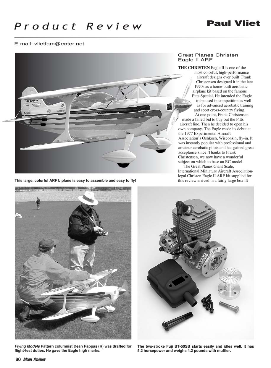
THE CHRISTEN Eagle II is one of the most colorful, high-performance aircraft designs ever built. Frank Christensen designed it in the late 1970s as a home-built aerobatic airplane kit based on the famous Pitts Special. He intended the Eagle to be used in competition as well as for advanced aerobatic training and sport cross-country flying.
At one point, Frank Christensen made a failed bid to buy out the Pitts aircraft line. Then he decided to open his own company. The Eagle made its debut at the 1977 Experimental Aircraft Association's Oshkosh, Wisconsin, fly-in. It was instantly popular with professional and amateur aerobatic pilots and has gained great acceptance since. Thanks to Frank Christensen, we now have a wonderful subject on which to base an RC model.
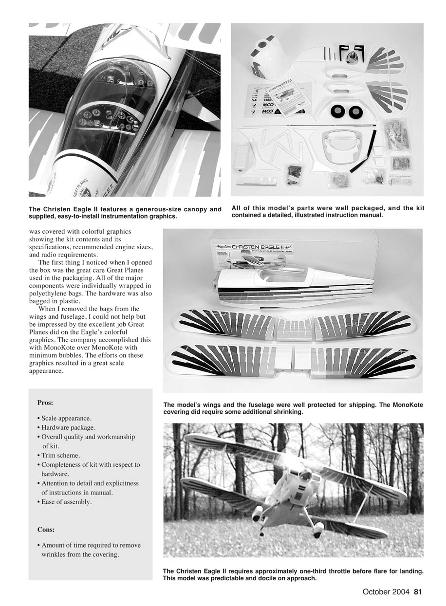
The Great Planes Giant Scale, International Miniature Aircraft Association-legal Christen Eagle II ARF kit supplied for this review arrived in a fairly large box. It was covered with colorful graphics showing the kit contents and its specifications, recommended engine sizes, and radio requirements.
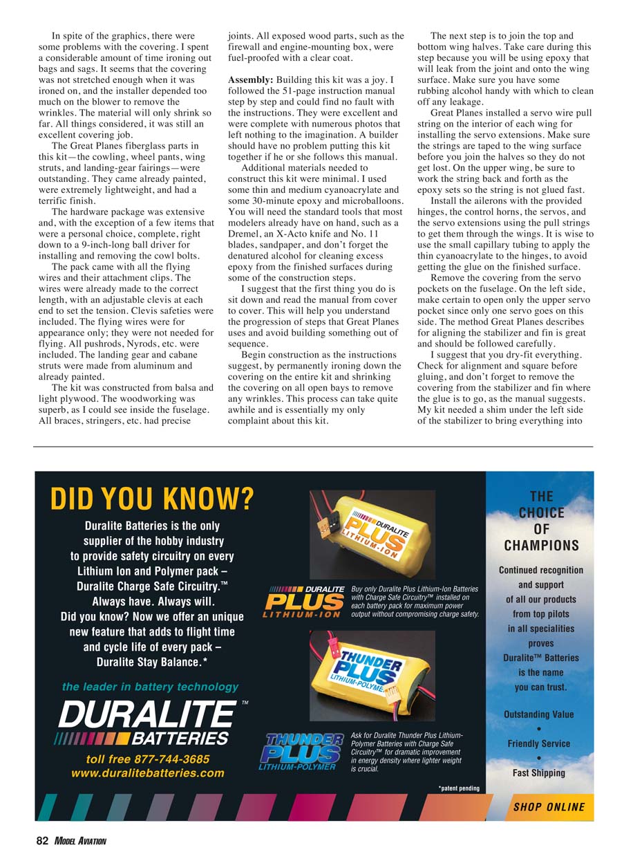
The first thing I noticed when I opened the box was the great care Great Planes used in the packaging. All of the major components were individually wrapped in polyethylene bags. The hardware was also bagged in plastic.
When I removed the bags from the wings and fuselage, I could not help but be impressed by the excellent job Great Planes did on the Eagle's colorful graphics. The company accomplished this with MonoKote over MonoKote with minimum bubbles. The efforts on these graphics resulted in a great scale appearance.
Pros
- Scale appearance.
- Extensive hardware package.
- Overall quality and workmanship of kit.
- Attractive trim scheme.
- Completeness of kit with respect to hardware.
- Attention to detail and explicitness of instructions in the manual.
- Ease of assembly.
Cons
- Amount of time required to remove wrinkles from the covering.
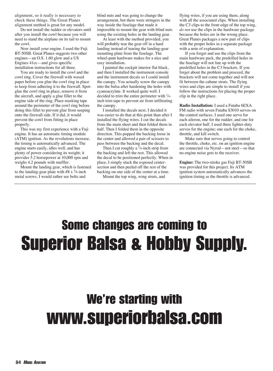
The model's wings and fuselage were well protected for shipping. The MonoKote covering did require some additional shrinking. In spite of the graphics, there were some problems with the covering. I spent a considerable amount of time ironing out bags and sags. It seems that the covering was not stretched enough when it was ironed on, and the installer depended too much on the blower to remove the wrinkles. The material will only shrink so far. All things considered, it was still an excellent covering job.
The Great Planes fiberglass parts in this kit—the cowling, wheel pants, wing struts, and landing-gear fairings—were outstanding. They came already painted, were extremely lightweight, and had a terrific finish.
The hardware package was extensive and, with the exception of a few items that were a personal choice, complete, right down to a 9-inch-long ball driver for installing and removing the cowl bolts.
The pack came with all the flying wires and their attachment clips. The wires were already made to the correct length, with an adjustable clevis at each end to set the tension. Clevis safeties were included. The flying wires were for appearance only; they were not needed for flying. All pushrods, Nyrods, etc., were included. The landing gear and cabane struts were made from aluminum and already painted.
The kit was constructed from balsa and light plywood. The woodworking was superb, as I could see inside the fuselage. All braces, stringers, etc., had precise joints. All exposed wood parts, such as the firewall and engine-mounting box, were fuel-proofed with a clear coat.
Assembly
Building this kit was a joy. I followed the 51-page instruction manual step by step and could find no fault with the instructions. They were excellent and were complete with numerous photos that left nothing to the imagination. A builder should have no problem putting this kit together if he or she follows this manual.
Additional materials needed to construct this kit were minimal. I used some thin and medium cyanoacrylate, some 30-minute epoxy, and microballoons. You will need the standard tools that most modelers already have on hand, such as a Dremel, an X-Acto knife and No. 11 blades, sandpaper, and denatured alcohol for cleaning excess epoxy from finished surfaces during some of the construction steps.
I suggest that the first thing you do is sit down and read the manual from cover to cover. This will help you understand the progression of steps that Great Planes uses and avoid building something out of sequence.
Begin construction as the instructions suggest, by permanently ironing down the covering on the entire kit and shrinking the covering on all open bays to remove any wrinkles. This process can take quite a while and is essentially my only complaint about this kit.
The next step is to join the top and bottom wing halves. Take care during this step because you will be using epoxy that will leak from the joint and onto the wing surface. Make sure you have some rubbing alcohol handy with which to clean off any leakage.
Great Planes installed a servo wire pull string on the interior of each wing for installing the servo extensions. Make sure the strings are taped to the wing surface before you join the halves so they do not get lost. On the upper wing, be sure to work the string back and forth as the epoxy sets so the string is not glued fast.
Install the ailerons with the provided hinges, the control horns, the servos, and the servo extensions using the pull strings to get them through the wings. It is wise to use small capillary tubing to apply the thin cyanoacrylate to the hinges to avoid getting glue on the finished surface.
Remove the covering from the servo pockets on the fuselage. On the left side, make certain to open only the upper servo pocket since only one servo goes on this side. The method Great Planes describes for aligning the stabilizer and fin is great and should be followed carefully.
I suggest that you dry-fit everything. Check for alignment and squareness before gluing, and don't forget to remove the covering from the stabilizer and fin where the glue is to go, as the manual suggests. My kit needed a shim under the left side of the stabilizer to bring everything into alignment, so it really is necessary to check these things. The Great Planes alignment method is great for any model.
Do not install the rudder or elevators until after you install the cowl because you will need to stand the airplane on its tail to mount the cowl.
Now install your engine. I used the Fuji BT-50SB. Great Planes suggests two other engines—an O.S. .160 glow and a US Engines 41cc—and gives specific installation instructions for all three.
You are ready to install the cowl and the cowl ring. Cover the firewall with waxed paper before you glue the cowl ring in place to keep from adhering it to the firewall. Spot-glue the cowl ring in place, remove it from the aircraft, and apply a glue fillet to the engine side of the ring. Place masking tape around the perimeter of the cowl ring before doing this fillet to prevent glue from seeping onto the firewall side. If it did, it would prevent the cowl from fitting in place properly.
This was my first experience with a Fuji engine. It has an automatic timing module (ATM) ignition. As the revolutions increase, the timing is automatically advanced. The engine starts easily, idles well, and has plenty of power considering its weight; it provides 5.2 horsepower at 10,000 rpm and weighs 4.2 pounds with muffler.
Mount the landing gear, which is fastened to the landing-gear plate with #8 x 5/8-inch metal screws. I would rather see bolts and blind nuts and was going to change the arrangement, but there were stringers in the way inside the fuselage that made it impossible to mount the gear with blind nuts using the existing holes in the landing gear.
At least with the method provided, you will probably tear the gear off in a hard landing instead of tearing the landing-gear mounting plate from the fuselage. The wheel-pant hardware makes for a nice and easy installation.
I painted the cockpit interior flat black, and then I installed the instrument console and the instrument decals so I could install the canopy. You actually screw the canopy in place to the balsa after hardening the holes with cyanoacrylate. It worked quite well. I decided to trim the entire perimeter with 1/4-inch trim tape to prevent air from infiltrating the canopy.
I installed the decals next. I found it easier to do that at this point than after I installed the flying wires. I cut the decals from the main sheet and then folded them in half. Then I folded them in the opposite direction. This popped the backing loose in the center and allowed a pair of scissors to pass between the backing and the decal.
Then I cut roughly a 1/4-inch strip from the backing and left the rest. This allowed the decal to be positioned perfectly. When in place, I simply stuck the exposed center section and then peeled off the rest of the backing on one side of the center at a time.
Mount the top wing, wing struts, and flying wires, if you are using them, along with all the associated clips. When installing the C3 clips to the front edge of the top wing, do not use the clips in the main hardware package because the holes are in the wrong place. Great Planes packages a new pair of clips with the proper holes in a separate package with a note of explanation.
If you forget and use the clips from the main hardware pack, the predrilled holes in the fuselage will not line up with the predrilled holes in the C3 brackets. If you proceed with the wrong clips, the brackets will not come together and will not fit between the cabane struts. The flying wires and clips are simple to install if you follow the instructions for placing the proper clip in the right place.
Radio Installation
I used a Futaba 6EXA FM radio with seven Futaba S3010 servos on the control surfaces. I used one servo for each aileron, one for the rudder, and one for each elevator half. I used three lighter-duty servos for the engine: one each for the choke, throttle, and kill switch.
Make sure that servos going to control the throttle, choke, etc., on an ignition engine are connected via Nyrod—not steel—so that no engine noise gets to the receiver.
Engine
The two-stroke gas Fuji BT-50SB was provided for this project. Its ATM ignition system automatically advances the ignition timing as the throttle is advanced. The engine starts easily and has plenty of power for sport aerobatics; it turned a Zinger 20 x 10 at a healthy 7,290 rpm in testing.
Battery Pack
I used an SR Batteries 2200 mAh pack to power the receiver and servos. At the company's suggestion, I used a five-cell pack instead of a four-cell pack. SR custom-wired the pack with two battery leads soldered directly to the cells.
With this arrangement I was able to use two separate on/off switches on the aircraft as an added safety measure against vibration.
Flying
I called Dean Pappas and asked him if he would be interested in test-flying the new Christen Eagle while I took pictures. He said he would be glad to do the honors, and his comments follow.
"The Fuji .50 was ground run long enough to verify that the mixture was set just slightly rich, and that the throttle transition was snappy. I have to say that the engine's table manners were perfectly civilized throughout the test, and starting was a painless procedure.
"The Fuji turned a Zinger 20 x 10 at a healthy 7,290 rpm, and it displayed a willingness to turn even more prop, which will wait until after break-in is complete. The performance was more than adequate for sport aerobatics and spirited horsing around; it was actually adequate for hovering and a briefer torque roll. For Sportsman IMAC use, the larger Fuji .64 would be more appropriate.
"Test flight day started out kind of on the windy side, but we decided to give it a go anyway. The Eagle was lined up on the runway after the usual tail-dragger-in-a-crosswind taxiing hassles, and the throttle was opened up. The Eagle tracked straight on takeoff every flight that day, an indication that the factory preset engine offset is correct. That same amount of thrust routed nicely through straight climbouts and vertical climbs.
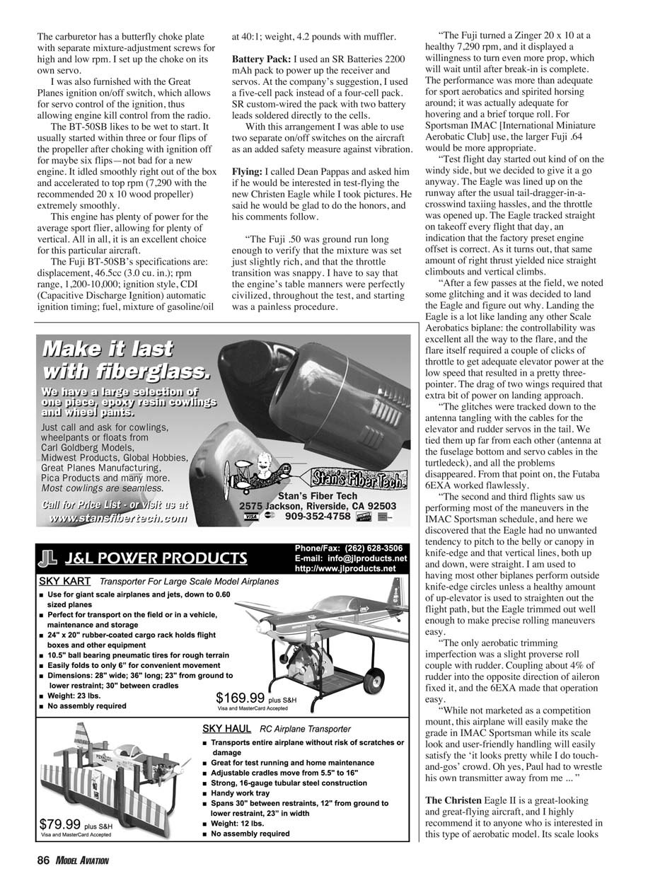
"After a few passes at the field, we noted some glitching and decided to land the Eagle and figure out why. Landing the Eagle is a lot like landing any other scale aerobatics biplane: the controllability was excellent all the way to the flare, and the flare itself required a couple of clicks of throttle to get adequate elevator power at the low speed that resulted in a pretty three-pointer. The drag of two wings required that extra bit of power on landing approach.
"The glitches were tracked down to the antenna tangling with the cables for the elevator and rudder servos in the tail. We tied them up far from each other (antenna at the fuselage bottom and servo cables in the turtledeck), and all the problems disappeared. From that point on, the Futaba 6EXA worked flawlessly.
"The second and third flights saw us performing most of the maneuvers in the IMAC Sportsman schedule, and here we discovered that the Eagle had no unwanted tendency to pitch to the belly of the canopy in knife-edge and that vertical lines, both up and down, were straight. I am used to having most other biplanes perform outside knife-edge circles unless a healthy amount of up-elevator is used to straighten out the flight path, but the Eagle trimmed out well enough to make precise rolling maneuvers easy.
"The only aerobatic trimming imperfection was a slight perverse roll couple with rudder. Coupling about 4% of rudder into the opposite direction of aileron fixed it, and the 6EXA made that operation easy.
"While not marketed as a competition mount, this airplane will easily make the grade in IMAC Sportsman while its scale look and user-friendly handling will easily satisfy the 'it looks pretty while I do touch-and-go's' crowd. Oh yes, Paul had to wrestle his own transmitter away from me ..."
The Christen Eagle II is a great-looking and great-flying aircraft, and I highly recommend it to anyone who is interested in this type of aerobatic model. Its scale looks and aerobatic abilities are sure to please most pilots.
The quality and workmanship are on par with or slightly better than most build-it-yourself kits. The kit is complete with the exception of an engine and radio and a fuel-tank stopper conversion if you use a gas engine, as I did.
This model will certainly draw a great deal of attention at the flightline. Out of a perfect 10, I give it an 8.5.
Specifications
- Aircraft type: Sport aerobatic biplane
- Wingspan: Top 68.5 inches; bottom 64.5 inches
- Wing chord: 11¾ inches
- Total wing area: 1,436 square inches
- Length: 62.5 inches
- Recommended weight: 16.5–18 pounds
- Review model’s ready-to-fly weight: 17 pounds, 15 ounces
- Recommended wing loading: 26–29 ounces per square foot
- Review model’s wing loading: 28.89 ounces per square foot
- Recommended engines: 1.60–2.20 two-stroke, 180–300 four-stroke, 2.0–3.2 cu. in. gas
- Engine used: Fuji BT-50SB gas
- Recommended radio: Four-channel, eight to nine servos
- Radio used: Futaba 6EXA, seven S3010 servos, three S148 servos, SR 2200 mAh battery pack
- Basic materials used: Balsa, plywood, fiberglass, MonoKote
- Manual: 51 pages
- Average retail price: $399
Manufacturer/Distributor
- Great Planes Model Manufacturing
Box 9021 Champaign, IL 61826 (217) 398-8970 www.greatplanes.com/airplanes/gpma1217.html
Also available from retail outlets.
Transcribed from original scans by AI. Minor OCR errors may remain.

