
Fun-Key Edge 540T ARF
We have probably all sat down with our new airplane magazines in hand and drooled over the newest models to grace the pages. After plopping down our hard-earned cash for an airplane that was supposed to do it all (according to the advertisements and the product reviews), we were then disappointed by how poorly it was constructed and, worst of all, how badly it flew!
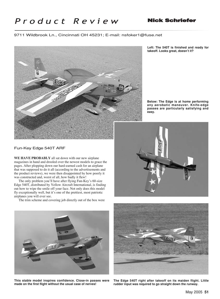
The only problem you'll have after flying Fun-Key's 60-size Edge 540T, distributed by Yellow Aircraft International, is finding out how to wipe the smile off your face. Not only does this model fly exceptionally well, but it's one of the prettiest, most patriotic airplanes you will ever see.
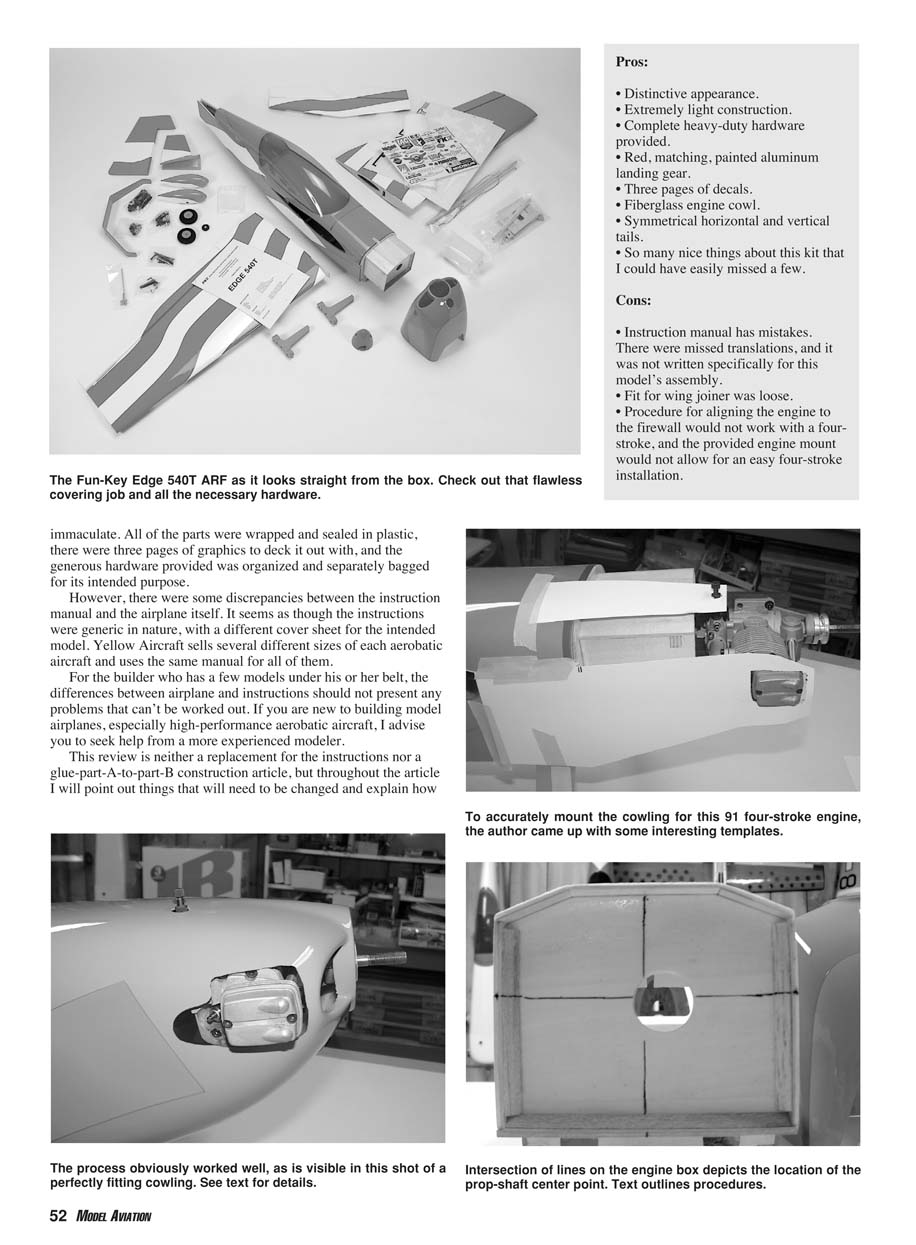
The trim scheme and covering job directly out of the box were immaculate. All of the parts were wrapped and sealed in plastic, there were three pages of graphics to deck it out with, and the generous hardware provided was organized and separately bagged for its intended purpose. However, there were some discrepancies between the instruction manual and the airplane itself. It seems as though the instructions were generic in nature, with a different cover sheet for the intended model. Yellow Aircraft sells several different sizes of each aerobatic aircraft and uses the same manual for all of them. For the builder who has a few models under his or her belt, the differences between airplane and instructions should not present any problems that can't be worked out. If you are new to building model airplanes, especially high-performance aerobatic aircraft, I advise you to seek help from a more experienced modeler.
This review is neither a replacement for the instructions nor a glue-part-A-to-part-B construction article, but throughout the article I will point out things that will need to be changed and explain how to do it. With these clarifications and modifications, you should be able to assemble your model so that it will fly the way an Edge begs to be flown.
Pros:
- Distinctive appearance.
- Extremely light construction.
- Complete heavy-duty hardware provided.
- Red, matching, painted aluminum landing gear.
- Three pages of decals.
- Fiberglass engine cowl.
- Symmetrical horizontal and vertical tails.
- So many nice things about this kit that I could have easily missed a few.
Cons:
- Instruction manual has mistakes and missed translations; it was not written specifically for this model’s assembly.
- Fit for the wing joiner was loose.
- Procedure for aligning the engine to the firewall would not work with a four-stroke, and the provided engine mount would not allow for an easy four-stroke installation.
Overview
I normally have my preferences concerning the hardware I use when building a new model. If I know I'm going to wring it out and do some stupid things with it, I'll use metal clevises along with heavier hardware. For the sake of a product review, I strictly use the hardware supplied with the kit.
All parts were wrapped and sealed in plastic, and the generous hardware was organized and separately bagged for its intended purpose. The manufacturer removed the bottom wing covering where the center fibreglass reinforcement is required, which is thoughtful, but the top covering in that area was left in place and the instructions did not tell you to remove it.
For the builder who has a few models under his or her belt, the differences between airplane and instructions should not present any problems that can't be worked out. If you are new to building model airplanes, especially high-performance aerobatic aircraft, seek help from a more experienced modeler. With the clarifications and modifications noted in this review, you should be able to assemble your model so that it will fly like an Edge.
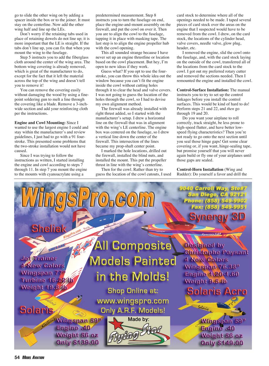
Look at all of the glue joints and add cyanoacrylate anywhere that looks a little shy on adhesive. The landing gear features an interesting design concept: a small hatch covers it so that you don't see the attaching screws, and the gear's plate is tied into the engine box and firewall with hardwood blocks. This should prevent any gear-plate separations from the rest of the fuselage on less-than-perfect landings.
The vertical tail is made from painted fiberglass instead of balsa and covering. I don't know why, but it was interesting.
Enough already! You will never see how well the Edge flies if we don't get started, so let's go!
Wing Assembly
You can forget the first two steps of the manual because they are not for this model; there are no removable hatches for the servos. Step 19 shows a picture of how the servos are actually mounted.
With your covering iron, seal the area the servo will fit into and then cut out the center opening for the servo. You will find a nice tube installed for the servo leads (no strings to pull the leads through are necessary). Add your servo-extension wire; a 12-inch one works nicely. Remember to secure the connection inside the wing; you don't want it coming apart. I taped mine together and slid it through to the middle of the wing.
Follow step 3 for the wing joiner, but you may have to add some scrap balsa to fill in where the receptacle for the wing joiner and the joiner itself have a loose fit. This will prevent you from adding weight in epoxy, which makes for a poor glue joint.
Make sure the joiner will stay centered and not slide in when you go to slide the other wing on by adding a spacer inside the box or to the joiner. It must stay on the centerline. Now add the other wing half and line up the leading edges.
Don't worry if the retaining tabs used in place of retaining dowels do not line up; it is more important that the leading edge is straight. If the tabs don't line up, you can fix that when you mount the wing to the fuselage.
Step 5 instructs you to add the fiberglass cloth around the center of the wing area. The bottom wing covering is already removed, which is great of the manufacturer to do, except for the fact that it left the material across the top of the wing and didn't tell you to remove it. You can remove the covering easily without damaging the wood by using a fine-point soldering gun to melt a line through the covering like a blade. Remove a 3-inch-wide section and add your reinforcing cloth per the instructions.
Engine and Cowl Mounting
Since I wanted to use the largest engine I could and stay within the manufacturer's and review guidelines, I went with a 91 four-stroke. This presented some problems that a two-stroke installation would not have caused.
Following steps 7 through 11 in the manual: step 7 tells you to mount the engine to the mounts with cyanoacrylate using a predetermined measurement. Step 8 instructs you to turn the fuselage on end, place the engine-and-mount assembly on the firewall, and put the cowl on over it. Then you are to align the cowl to the fuselage, tapping it in place with masking tape. The last step is to align the engine propeller hub with the cowl opening.
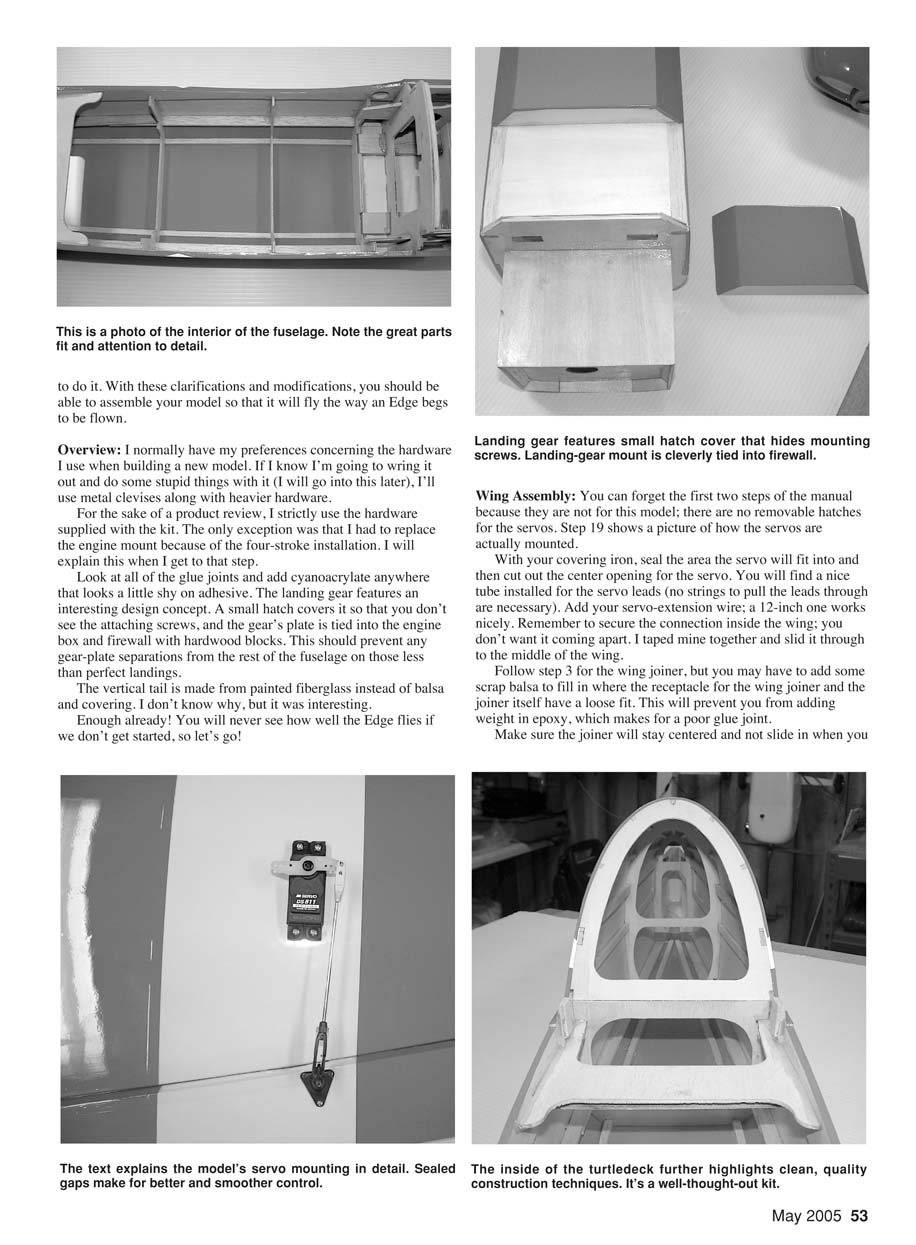
This sounded strange because I have never set up an engine thrustline or location based on the cowl placement. If you opt to use the four-stroke, you can throw this whole idea out the window because you can't fit the engine inside the cowl without cutting holes through it to clear the head and valve covers. I was not going to guess the location of the holes through the cowl, so I had to devise my own alignment method.
The firewall was already installed with right thrust added, so I started with the manufacturer's setup. I drew a horizontal line on the firewall that was in alignment with the wing's leading-edge centerline. The engine box was centered on the fuselage, so I drew a vertical line down the center of the firewall. This intersection of the lines became my prop-shaft center point.
I marked the hole locations, drilled out the firewall, installed the blind nuts, and installed the mount. This put the propeller thrust in line with the wing's centerline.
Then for the cowl. Rather than try to guess the location of the cowl cutouts, I used card stock to determine where all of the openings needed to be made. I taped several pieces of card stock over the areas on the engine that I suspected would have to be cleared by the cowl. I drew on the card stock the locations of the cylinder head, valve covers, needle valve, glow plug, header, etc.
I removed the engine, slid the cowl onto the fuselage, and, with the card stock laying on the outside of the cowl, transferred all of the locations from the card stock to the cowl. I used my rotary cutter and removed the sections needed. Then I remounted the engine and installed the cowl.
Control-Surface Installation
The manual instructs you to try to set up the control linkages before you install the control surfaces. This would be kind of hard to do! Perform steps 21 and 22, and then go through steps 19 and 20.
Do you want your airplane to roll correctly, track straight, be less prone to high-speed flutter, and have better low-speed flying characteristics? Then you're not ready to go onto the next section until you seal those hinge gaps! Get some clear covering or hinge-sealing tape, but promise yourself that you will never again build or fly one of your airplanes until those gaps are sealed.
Control-Horn Installation (Wing and Rudder)
Do yourself a favor and drill the holes in the control horns for the nylon retaining bolts. This will ensure that the bolts stay centered and don't ratchet out.
I used the supplied steel pushrods throughout the model, rather than the threaded rods provided. Enlarge the holes in the control horns to 5/64 in. so that the supplied clevises will fit. If you intend to perform abusive aerobatics, you might want to replace them with the metal clevis variety.
Pretap the control-horn nut plates with one of the 2 x 32mm bolts. Chuck one up in your electric drill and go to it—your fingers will thank you!
Perform the rest of the installation as noted, except that with your servo control arm on the servo and positioned at 90° to the servo case, make a reference line as instructed. Instead of positioning the control horn on that line, move it inward toward the center of the servo 1/8 inch. This will give you the correct geometry on your linkage setup for a rock-solid hold at maximum throws.
Step 20 has you looking for a hole (that does not exist) in the rudder. This hole is for the threaded rod that is hooked up to the pull-pull cables. Figure out where the cables should exit the fuselage, and then drill out the rudder and install the rod as instructed.
If you only want to fly the pattern around the field, this control rod will be fine. If you plan on doing many knife-edge maneuvers, go with some type of control arm through the rudder that supports itself on each side of the rudder.
I used #8 all-thread and two nuts. I also bent the all-thread so that the threaded couplers would line up on the hinge line. That way my pull-pull setup had equal throw, and I have no loose cables, even at extreme throws.
Radio Installation
The first thing you’ll probably notice while looking inside the fuselage is that the servo tray can be installed in the best location to help balance your model. This allows for different engine weights without having to add dead weight to the airplane—a nice touch.
I installed the servos in the tray and slid it back and forth to achieve the correct center of gravity. I didn’t glue it down at this point because I still had to make and install the elevator-pushrod assembly. You may have to shim the tray so that the servos don’t bottom out against the fuselage.
I temporarily tacked the tray in place and moved on to the pull-pull cables and pushrods. With everything on the airplane and using a 91 four-stroke, moving the tray allowed me to find the proper C.G. without adding extra weight.
The control-surface throws were conservative from the factory. I bumped all of the 3/8-inch throws up to 1/2 inch for a low rate, with roughly 30% exponential. Then I set up a high rate for maximum travels, with 70–90% exponential.
I think you will find the low rate great for most sport-flying. If you’re not ready for a wild ride, don’t max out your throws. Just set them slightly higher and experiment with them to find what you like best. If you do not have a radio with high and low rates, follow the manufacturer’s recommendations. You can add throw if you need more.
Flight Performance
This is the best part of any review. After running up the engine and making sure it would run reliably, I checked the battery once last time and then performed a ground check of the radio with the engine running.
Everything looked good, so I taxied the Edge out to the runway and started the takeoff roll. As I slowly increased the aircraft’s throttle, I readied myself to add rudder, but it went straight down the centerline. A touch of up-elevator with a shallow climbout, and the airplane was on its way.
After the first turn I leveled it off and checked the trim. A couple clicks of right aileron and three clicks of up-trim was all that was needed, and I felt instantly comfortable with the airplane.
High-speed flight was very fast, and this 540T tracked like it was on rails. Inverted flight was a breeze; I only had to add slight pressure on the stick to maintain flight. I tried some vertical lines and then flew this year’s International Miniature Aerobatic Club Sportsman sequence.
I was amazed by how well this model performed on its maiden flight. My knees had stopped knocking right after takeoff, and I was having fun!
The photographer told me that once I felt comfortable with the airplane I should bring it down a bit lower for some flybys. I told him I was okay with it and brought the Edge down for a low pass. That felt pretty good, so I rolled to knife edge on the backside of the pattern. The model needed only slight correction for tucking toward the canopy—no big deal.
As I brought the airplane down for the next photo pass, I told the photographer to get ready for a low knife-edge pass. As I rolled the wings vertical, I let the model come down a little lower than expected before adding enough top rudder to sustain knife-edge flight.
As the Edge flew past, I realized that it was below the corn out in the field and, because of the crown in our runway, only roughly two feet off the ground. For a moment I started to panic (remembering that this was a maiden flight and I did not know what to expect yet). Then a calm came over me because this airplane felt like I had flown it many times before.
At that point the photographer and a fellow club member started heckling me about getting the model a little lower for the next pass, so I did. I set things up and did a one-foot-off-the-runway knife-edge flyby. Feeling extremely cocky, I performed knife edge with a snap and back to knife edge, Lomcevaks, Waterfalls, and Blenders. I remind you that this was the maiden flight.
After a completely uneventful landing, the photographer said that I had to take the Edge back up and try some other things with it. I told him that I didn't think much more could be done to check its flying capabilities.
I refueled the airplane and flew it once more to check its slow-speed stall at idle and at full up-elevator. All it did was mush forward, and then it began flying again, with no tip-stalling tendencies. This was unbelievable for an airplane with such a thin wing. The ability to stay in the air at such a slow airspeed has to be attributed to the wing's design and the model's low weight. This is a great aircraft that can do it all.
Distributor
Yellow Aircraft International 203 Massachusetts Ave. Lexington, MA 02420 (781) 674-9898 Fax: (781) 674-2281 www.yellowaircraft.com Price: $249
Specifications
- Length: 52.5 inches
- Wingspan: 60 inches
- Wing area: 687 square inches
- Weight: 6.8–7.3 pounds
- Review model's ready-to-fly weight with 91 engine, 1100 mAh battery pack: 6 pounds, 8 ounces
- Recommended engine: .60–.80 two-stroke or 70–90 four-stroke
- Engine used: Magnum 91 four-stroke
- Recommended radio: Four channel with five servos
- Radio used: JR 8103 with four DS811 digital servos on control surfaces, Expert Electronics SL561 servo for throttle, JR eight-channel FM receiver
- Propeller used: Zinger 14 x 6
Products used in review
JR 8103 radio, JR DS811 digital servos: Horizon Hobby 4105 Fieldstone Rd. Champaign, IL 61822 (217) 352-1913 www.horizonhobby.com
Magnum 91 engine: Hobby People 18480 Bandilier Cir. Fountain Valley, CA 92708 (714) 963-9881 www.hobbypeople.net
Zinger 14 x 6 propeller: Zinger Propeller 25029 S. Vermont Ave. Harbor City, CA 90710 (310) 539-2313 www.zingerpropeller.com
Transcribed from original scans by AI. Minor OCR errors may remain.

