

Product Review
Paul Vliet
658 Clearfield Rd., Nazareth PA 18064
Pacific Aeromodel Tiger Moth ARF
DE HAVILLAND BUILT the Tiger Moth biplane in the 1930s; the Royal Air Force (RAF) and others used it to train pilots before World War II. The RAF continued to employ the aircraft until roughly 1950. Many were used in civil aviation and remain in use to this day.
The Tiger Moth prototype—the D.H.82—evolved from the D.H.60 Gipsy Moth and first flew, with its 120-horsepower de Havilland Gipsy Moth engine, on October 26, 1931. Most of the later Tiger Moths were powered by Gipsy Major I 130-horsepower engines. More than 7,000 of the biplanes had been built by the end of WW II.
The Tiger Moth had a length of 23 feet, 11 inches, and a wingspan of 29 feet, 4 inches. The loaded weight was approximately 1,800 pounds.
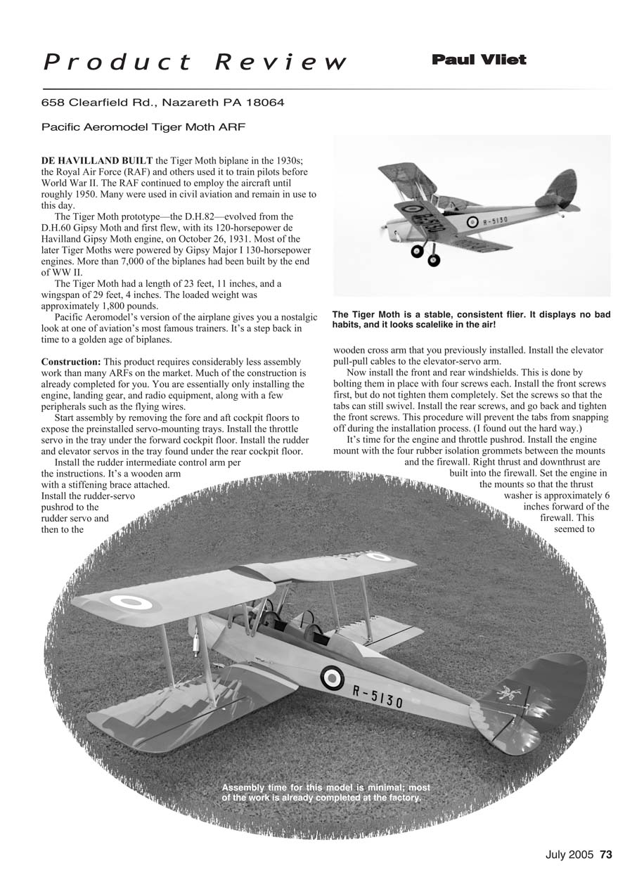
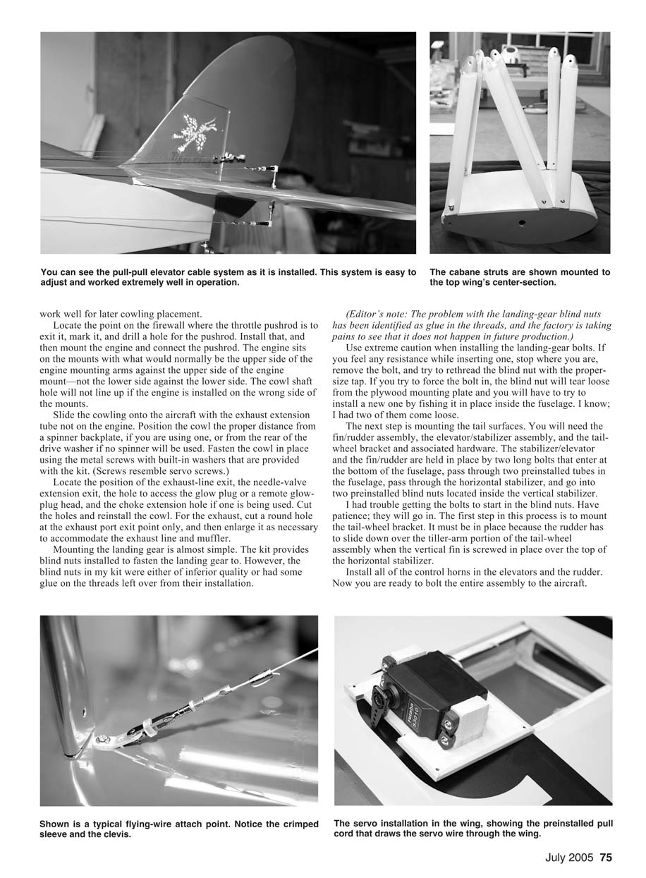
Pacific Aeromodel's version of the airplane gives you a nostalgic look at one of aviation's most famous trainers. It's a step back in time to a golden age of biplanes.
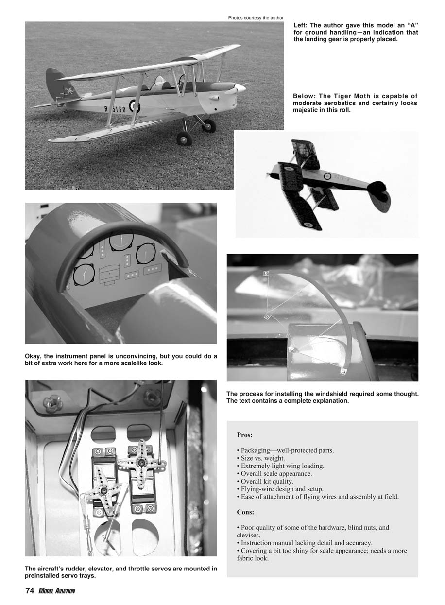
Construction: This product requires considerably less assembly work than many ARFs on the market. Much of the construction is already completed for you. You are essentially only installing the engine, landing gear, and radio equipment, along with a few peripherals such as the flying wires.
Start assembly by removing the fore and aft cockpit floors to expose the preinstalled servo-mounting trays. Install the throttle servo in the tray under the forward cockpit floor. Install the rudder and elevator servos in the tray found under the rear cockpit floor.
Install the rudder intermediate control arm per the instructions. It's a wooden arm with a stiffening brace attached.
Install the rudder-servo pushrod to the rudder servo and then to the wooden cross arm that you previously installed. Install the elevator pull-pull cables to the elevator-servo arm.
Now install the front and rear windshields. This is done by bolting them in place with four screws each. Install the front screws first, but do not tighten them completely. Set the screws so that the tabs can still swivel. Install the rear screws, and go back and tighten the front screws. This procedure will prevent the tabs from snapping off during the installation process. (I found out the hard way.)
It's time for the engine and throttle pushrod. Install the engine mount with the four rubber isolation grommets between the mounts and the firewall. Right thrust and downthrust are built into the firewall. Set the engine in the mounts so that the thrust washer is approximately 6 inches forward of the firewall. This seemed to work well for later cowling placement.
Left: The author gave this model an "A" for ground handling—an indication that the landing gear is properly placed.
Below: The Tiger Moth is capable of moderate aerobatics and certainly looks majestic in this roll.
Okay, the instrument panel is unconvincing, but you could do a bit of extra work here for a more scalelike look.
The process for installing the windshield required some thought. The text contains a complete explanation.
The aircraft's rudder, elevator, and throttle servos are mounted in preinstalled servo trays.
Pros:
- Packaging—well-protected parts.
- Size vs. weight.
- Extremely light wing loading.
- Overall scale appearance.
- Overall kit quality.
- Flying-wire design and setup.
- Ease of attachment of flying wires and assembly at field.
Cons:
- Poor quality of some of the hardware, blind nuts, and clevises.
- Instruction manual lacking detail and accuracy.
- Covering a bit too shiny for scale appearance; needs a more fabric look.
Locate the point on the firewall where the throttle pushrod is to exit it, mark it, and drill a hole for the pushrod. Install that, and then mount the engine and connect the pushrod. The engine sits on the mounts with what would normally be the upper side of the engine mounting arms against the upper side of the engine mount—not the lower side against the lower side. The cowl shaft hole will not line up if the engine is installed on the wrong side of the mounts.
Slide the cowling onto the aircraft with the exhaust extension tube not on the engine. Position the cowl the proper distance from a spinner backplate, if you are using one, or from the rear of the drive washer if no spinner will be used. Fasten the cowl in place using the metal screws with built-in washers that are provided with the kit. (Screws resemble servo screws.)
Locate the position of the exhaust-line exit, the needle-valve extension exit, the hole to access the glow plug or a remote glow-plug head, and the choke extension hole if one is being used. Cut the holes and reinstall the cowl. For the exhaust, cut a round hole at the exhaust port exit point only, and then enlarge it as necessary to accommodate the exhaust line and muffler.
Mounting the landing gear is almost simple. The kit provides blind nuts installed to fasten the landing gear to. However, the blind nuts in my kit were either of inferior quality or had some glue on the threads left over from their installation.
(Editor’s note: The problem with the landing-gear blind nuts has been identified as glue in the threads, and the factory is taking pains to ensure that it does not happen in future production.)
Use extreme caution when installing the landing-gear bolts. If you feel any resistance while inserting one stop where you are, remove the bolt, and try to rethread the blind nut with the proper-size tap. If you try to force the bolt in, the blind nut will tear loose from the plywood mounting plate and you will have to try to install a new one by fishing it in place inside the fuselage. I know; I had two of them come loose.
The next step is mounting the tail surfaces. You will need the fin/rudder assembly, the elevator/stabilizer assembly, and the tailwheel bracket and associated hardware. The stabilizer/elevator and the fin/rudder are held in place by two long bolts that enter at the bottom of the fuselage, pass through two preinstalled tubes in the fuselage, pass through the horizontal stabilizer, and go into two preinstalled blind nuts located inside the vertical stabilizer.
I had trouble getting the bolts to start in the blind nuts. Have patience; they will go in. The first step in this process is to mount the tail-wheel bracket. It must be in place because the rudder has to slide down over the tiller-arm portion of the tail-wheel assembly when the vertical fin is screwed in place over the top of the horizontal stabilizer.
Install all of the control horns in the elevators and the rudder. Now you are ready to bolt the entire assembly to the aircraft.
Install the aileron servos to the servo bay doors, which have preinstalled hardwood posts mounted to them for this purpose. Screw the servos to the posts and pull the servo leads, along with the servo-lead extension wires, through the wing using the preinstalled string that is factory-set in the wing for this purpose. Screw the bay doors in place. Long five-hole servo arms are necessary to clear the servo bay doors. Install the aileron control horns and connect the servo pushrods.
It is time to join the lower wing halves and install the flying-wire brackets. At this point the instruction manual and the aircraft do not match at all; the process had been simplified compared to what is shown in the photos. Instead of having to install metal strut brackets, plywood tabs protrude from the wing that the strut slips over and then through bolts to.
The flying wires are then fastened to separate brackets that are metal-screwed to spots on the wing that are dimpled to show the mounting position. Mount the brackets to the wing at these positions.
Join the wing halves by sliding a 3/8-inch aluminum tube spar into the forward hole of one wing panel and the 1/8-inch aluminum rod into the rear hole in the same wing panel. Slip the second wing panel over the rods, and slide it in place up against the first panel. There are two sets of tubes and rods; the longer set is for the upper wing.
Turn the fuselage upside down in a cradle. To mount the lower wing, insert the stud at the LE of the lower wing into the square hole in the fuselage at the forward end of the wing saddle. I had to round the top portion of the stud with a Dremel tool to get it to enter the hole in the fuselage.
Fasten the wing in place using the two 1/4-20 nylon bolts provided. Turn the fuselage right-side up and set aside.
Install the cabane struts per the instruction manual labels S, M, and L by slipping them over the plywood studs on the top-wing center-section and bolting them in place. (See the addendum to the instruction manual.)
Be sure not to forget to install the flying-wire brackets to the rear cabane strut when bolting it in place because it uses the same bolt that holds the strut in place. Turn the wing center-section over after all six cabane struts are bolted on, and then fasten the center-section to the fuselage. Using the metal screws provided, attach the cabanes fast at the locations indicated on the fuselage by dimples.
Slide the longer tube spar and rod in place in the upper-wing center-section, and slip the wing panels in place on their respective sides. Install the wing struts. They are cut to exact length and are prebored to accept the bolts and lock nuts provided.
The fore and aft struts are longer than one another; the rear strut is the longest. It is installed with the sharpest angle going to the bottom wing, and the front strut is installed with the sharpest angle going to the top wing. The easiest way to install the struts is to have both wings in place and to raise the top wing enough to get the struts over the tabs.
Adjust the length of the flying wires after both wings are in place. The wires are made to approximate length at the factory. The end with the single clevis is fixed, and the ends with the two clevises are adjustable since the crimp tubes are left uncrimped, as is the case with the elevator/rudder end of the pull-pull cables.
The single-clevis end of the flying wires goes to the attachment point at the fuselage end of the wire, and the other two ends attach to the strut end of the wire. This is the adjustable end.
Adjust all of the clevises to maximum length. Snap the single clevis onto the fuselage side on the top or bottom attachment point. If you choose the bottom point at the fuselage, the other two clevises are attached to the upper attachment points on the struts.
Undo the loop of cable from the strut end of one clevis. Pull it as tight as possible by hand and clamp it in place. I used a pair of hemostats. Slide the end of the cable through the crimp connector, loop it back and through the connector again, pull the loop tight, and crimp the connector. Repeat this process for the other side of this flying-wire set, and then repeat it for the other three sets of flying wires.
Tighten all the wires by screwing in on the clevises until the wires twang a little—sort of like a guitar string but not quite that taut. Set the pull-pull cables on the elevator and rudder in the same manner.
I installed the radio at the location the plans indicated. That spot requires servolead extensions to reach the receiver. I strapped a 1500 mAh battery pack across the fuselage, but first I epoxied a piece of 1/4 aircraft plywood in place across the fuselage in the radio bay. The wood had four holes in it for wire ties; two were for the battery pack and two were for the receiver. I mounted the switch in the spot on the forward cockpit dash that was precut for it and ran the charging jack into the second precut hole.
Constructing this aircraft was fairly easy. Most of the work was finished before I opened the box. The instruction manual leaves a lot to be desired since many of the photos do not match the current kit. However, there are two addenda attached to the manual.
Some of the hardware could stand improvement. Many of the clevises did not thread well onto the brass connectors for the flying wires and pull-pull cables. As I mentioned, the blind nuts on the landing gear threaded so poorly that two of them tore loose.
Test Flight: The Tiger Moth was a treat to fly; it's a great performer overall. After range-testing the radio equipment and checking the control throws one last time, I wanted to see what this aircraft could do. I taxied to the center of the runway without a hitch. I give it an "A" for ground handling.
The takeoff roll was nice and straight, with only minimum right rudder and a bit of back pressure on the stick. The 120-size four-stroke had more than ample power, and the Moth was able to lift off gently in a scale fashion at half throttle and climb out.
I took it to a safe altitude and set the trims. The elevator took quite a few clicks on down-trim for the aircraft to fly without each of the first several flights. I found that they stretched and needed tightening. The flying wires on this aircraft are real and necessary, and it is essential that proper tension be maintained at all times. MA
Specifications:
Wingspan: 78 inches Wing area: 1,841 square inches Weight: 11 pounds, 7 ounces Wing loading: 14.32 ounces/square foot Length: 65.7 inches Engine: .90 cu. in. two-stroke or 120 cu. in., four-stroke (Magnum 120 four-stroke was used) Radio: Four channels, five servos (two for ailerons, one for elevator, one for rudder, and one for throttle)
Manufacturer:
Pacific Aeromodel Mfg. Inc. 12368 Valley Blvd. Suite 109 El Monte CA 91732 (626) 618-0300 or (800) 780-0100 (for orders) [email protected] www.pacaeromodel.com Price: $399.99
Transcribed from original scans by AI. Minor OCR errors may remain.

