

Product Review: Polk’s Hobby Tracker III RC System
Bob Aberle [email protected]
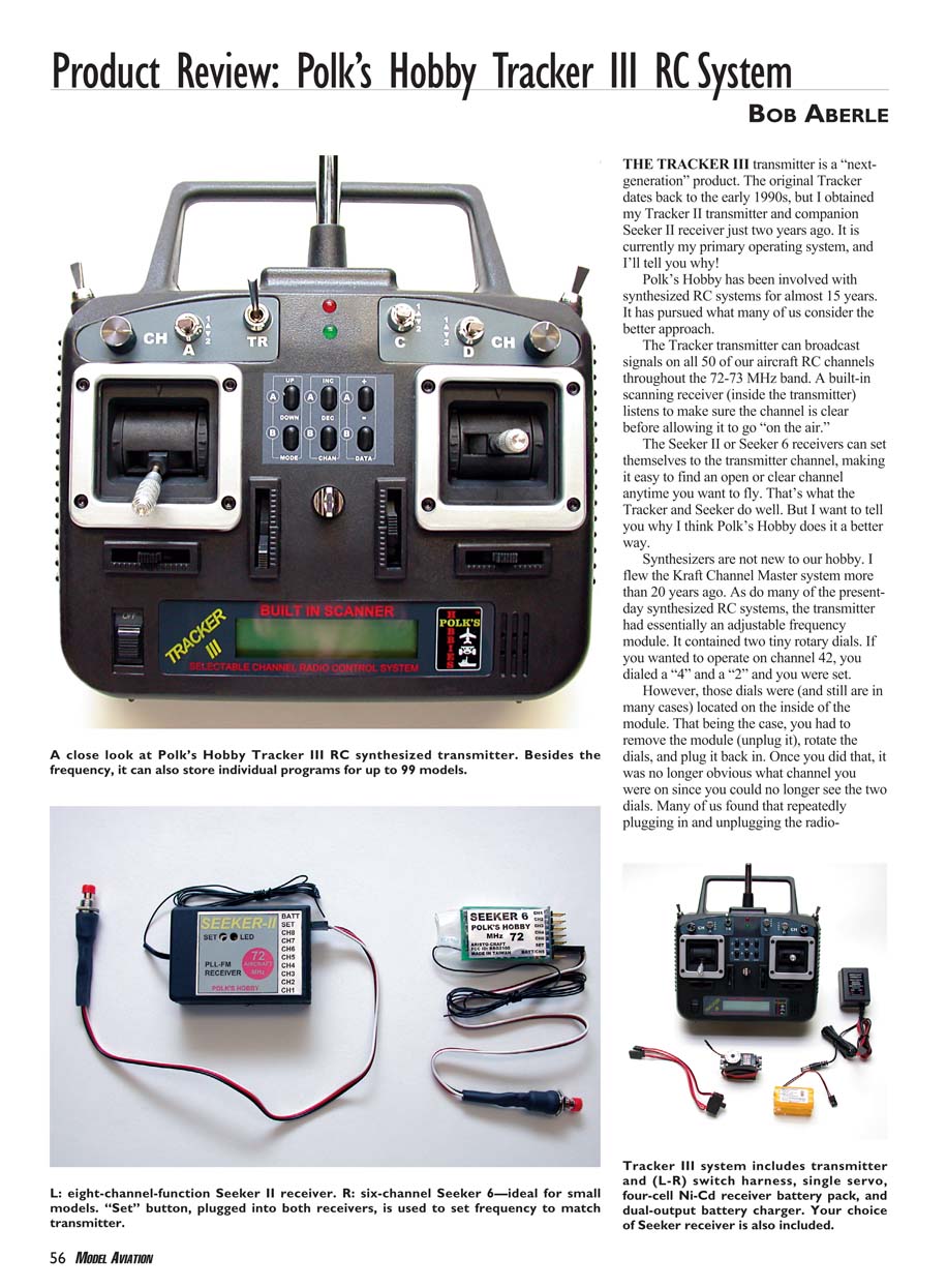
The Tracker III transmitter is a "next-generation" product. The original Tracker dates back to the early 1990s, but I obtained my Tracker II transmitter and companion Seeker II receiver just two years ago. It is currently my primary operating system, and I'll tell you why.
Polk's Hobby has been involved with synthesized RC systems for almost 15 years. It has pursued what many of us consider the better approach.
The Tracker transmitter can broadcast signals on all 50 of the aircraft RC channels throughout the 72–73 MHz band. A built-in scanning receiver (inside the transmitter) listens to make sure the channel is clear before allowing it to go "on the air."
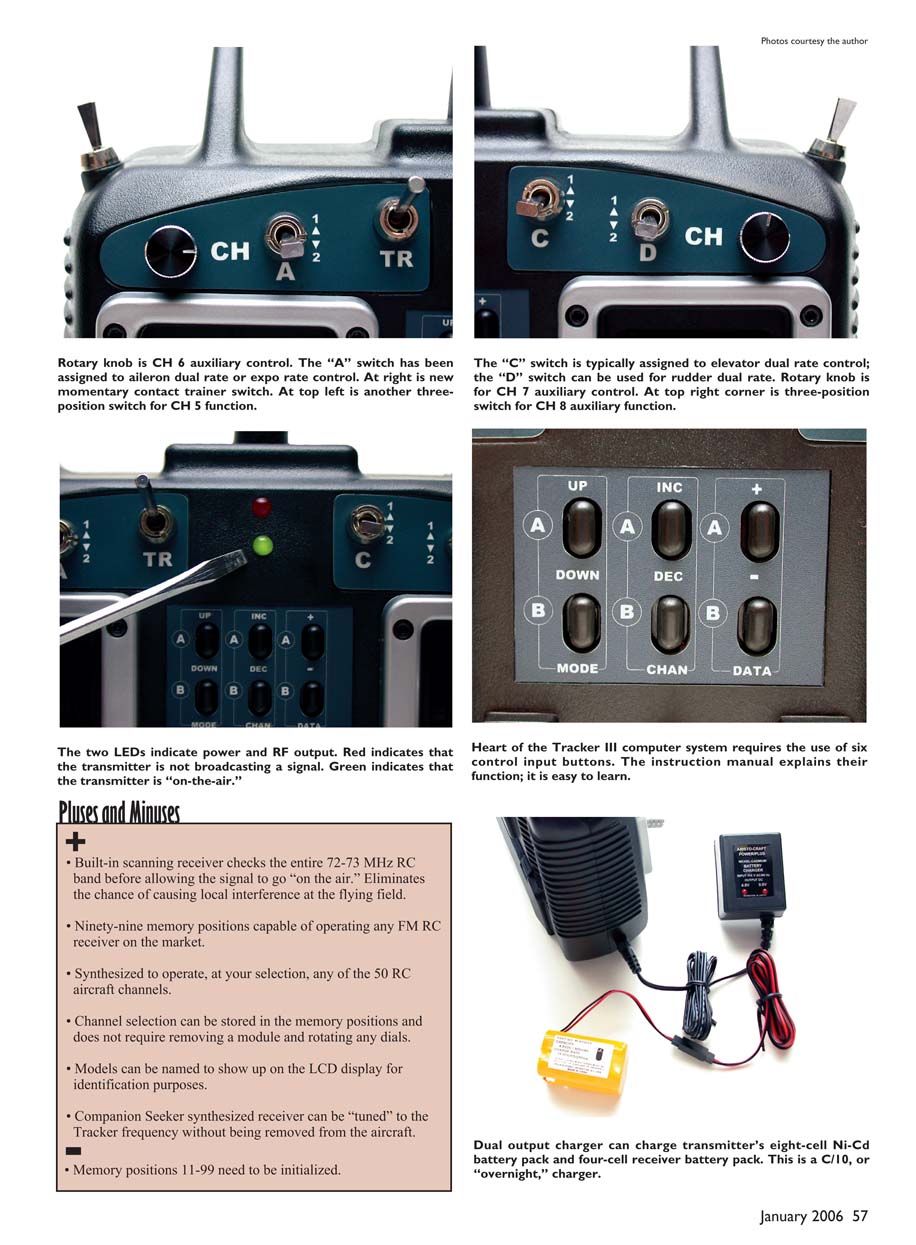
The Seeker II or Seeker 6 receivers can set themselves to the transmitter channel, making it easy to find an open or clear channel anytime you want to fly. That's what the Tracker and Seeker do well. But I want to tell you why I think Polk's Hobby does it a better way.
Synthesizers are not new to our hobby. I flew the Kraft Channel Master system more than 20 years ago. As do many of the present-day synthesized RC systems, the transmitter had essentially an adjustable frequency module. It contained two tiny rotary dials. If you wanted to operate on channel 42, you dialed a "4" and a "2" and you were set.
However, those dials were (and still are in many cases) located on the inside of the module. That being the case, you had to remove the module (unplug it), rotate the dials, and plug it back in. Once you did that, it was no longer obvious what channel you were on since you could no longer see the two dials. Many of us found that repeatedly plugging in and unplugging the radio module wore out the connector pins.
Frequency (RF) modules eventually wore out the connector pins. If you have a transmitter with six or seven model programs, you may be using several different RC channels. In the course of one day at the field and having several models with you, you might be pulling and resetting that synthesized module many times. How does Polk's Hobby address this problem? It has resorted to a pure electronic (solid-state) approach. There are no dials to rotate; it is all done much as it would be on a computer.
When you are first setting up a new transmitter it is all done electronically via the keypad and menus. That means it is possible to operate Airtronics and JR receivers, which are on high deviation (positive shift), and FMA Direct, Futaba, Hitec, and Ace receivers, which are on low deviation (negative shift). Likewise, the Seeker receivers will work with any other FM (PPM) transmitter since they automatically detect deviation.
How does Polk’s Hobby market its Tracker III transmitter and the Seeker receivers? For the US market the company offers systems on the 72 MHz aircraft channels and 75 MHz for the surface-vehicle market.
An eight-channel Tracker III transmitter with a Seeker 6 receiver, dual-output charger, four-cell Ni-Cd receiver battery pack, a Polk’s servo (item PLK12003), and a miniswitch currently sells for $180. The rationale for offering a single servo is that most modelers have their own preferences, and there is no point in supplying four servos that might never be used. Polk’s supplies one to let you get accustomed to the system operation.
The system I just described but with an eight-channel Seeker II receiver is $200. There are other combinations, as well as systems on 35 and 40 MHz for the European market. You can check out these options on Polk’s Hobby’s Web site.
Key Features
- Built-in scanning receiver checks the entire 72–73 MHz RC band before allowing the signal to go "on the air," eliminating the chance of causing local interference at the flying field.
- Ninety-nine memory positions capable of operating any FM RC receiver on the market.
- Synthesized to operate, at your selection, any of the 50 RC aircraft channels.
- Channel selection can be stored in the memory positions and does not require removing a module and rotating any dials.
- Models can be named to show up on the LCD display for identification purposes.
- Companion Seeker synthesized receiver can be "tuned" to the Tracker frequency without being removed from the aircraft.
Pluses and Minuses
+ The Tracker III is synthesized, solid-state, and scans the band before transmitting. + Supports 50 aircraft channels and 99 model memories. + Model naming on the LCD and Seeker receivers that tune without removal. + Comfortable, cleaner case design and conventional trim levers with Trim Memory.
- Memory positions 11–99 need to be initialized (travel volumes, trim rates, and dual rates are set to 0% by default).
- The RF output meter is gone; replaced by red/green LEDs (red = not broadcasting or low battery, green = broadcasting).
- Model-memory position number (1–99) no longer appears on the LCD screen (only the model name displays).
- Some auxiliary switches are in different locations compared to the Tracker II, which may confuse fliers using both.
- No frequency flag supplied.
There is no additional primary-article text beyond photo captions and the "Pluses and Minuses" box on the original page.
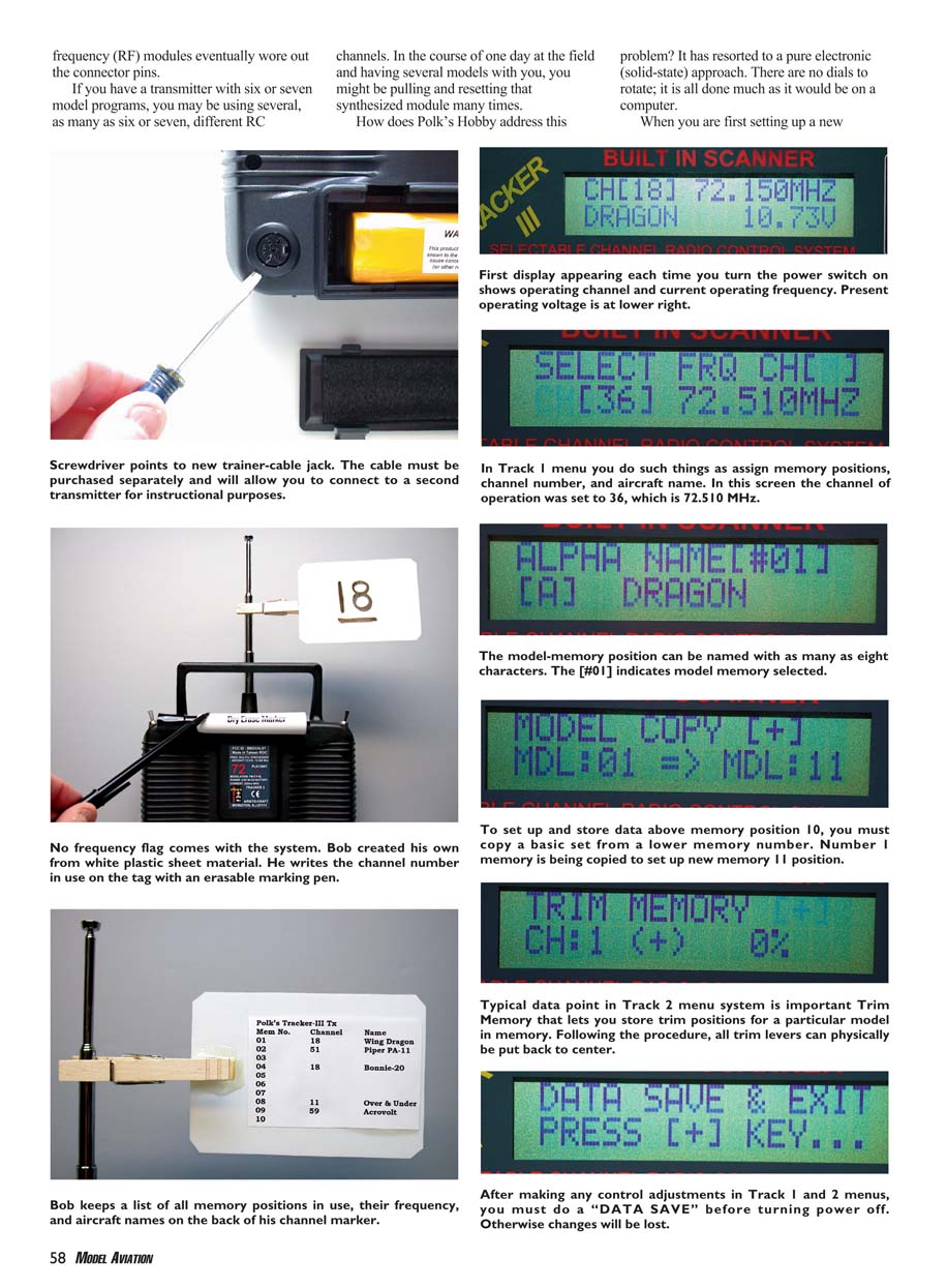
The Tracker III’s heart is a computer system that requires the use of six control-input buttons. The instruction manual explains their function; they are easy to learn. The dual output charger can charge the transmitter's eight-cell Ni-Cd battery pack and a four-cell receiver battery pack. This is a C/10, or "overnight," charger.
The two LEDs indicate power and RF output. Red indicates that the transmitter is not broadcasting a signal (or battery is too low). Green indicates that the transmitter is "on-the-air." At the top right corner is a three-position switch for CH 8 auxiliary function; at the top left is another three-position switch for CH 5. The "A" switch is typically assigned to aileron dual rate or expo rate control; the "C" switch typically assigned to elevator dual rate; the "D" switch can be used for rudder dual rate. Rotary knobs are for CH 6 and CH 7 auxiliary controls. At right is a new momentary-contact trainer switch.
The Track 2 menu allows you to assign switches and adjust many functions. You can actually assign all the switches to positions of your choice; this is done in the Track 2 menu. Polk's engineers told me that the "UP" and "DOWN" mode buttons must be pressed at the same time to enter Track 2 — this was done intentionally so you don't accidentally get into that menu while flying.
Tracker III Details
You will notice a newly designed and stylish case with more rounded corners and a cleaner appearance. This case is more comfortable to hold and easier to keep clean.
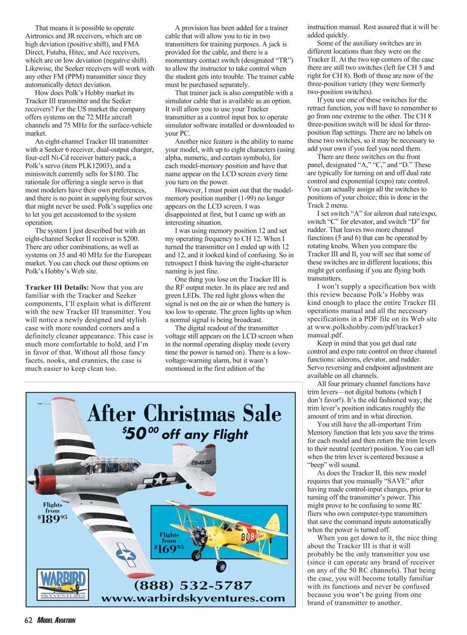
A provision has been added for a trainer cable that will allow you to tie in two transmitters for training purposes. A jack is provided for the cable and there is a momentary-contact switch (designated "TR") to allow the instructor to take control when the student gets into trouble. The trainer cable must be purchased separately.
That trainer jack is also compatible with a simulator cable that is available as an option. It will allow you to use your Tracker transmitter as a control input box to operate simulator software installed or downloaded to your PC.
Another nice feature is the ability to name your model, with up to eight characters (using alpha, numeric, and certain symbols), for each model-memory position and have that name appear on the LCD screen every time you turn on the power. However, the model-memory position number (1–99) no longer appears; initially this seemed confusing, but the model name usually provides clearer identification.
The RF output meter from earlier models is replaced by the red and green LEDs described above. The digital readout of the transmitter voltage still appears on the LCD screen in the normal operating display mode every time the power is turned on. There is a low-voltage-warning alarm; it wasn’t mentioned in the first edition of the instruction manual but will be added.
Some auxiliary switches are in different locations than they were on the Tracker II. At the two top corners there are still two switches (left for CH 5 and right for CH 8), now three-position switches rather than two-position. If you use one of these switches for retract function, you will have to remember to go from one extreme to the other. The CH 8 three-position switch will be ideal for three-position flap settings. There are no labels on these two switches, so you may want to add your own.
There are three switches on the front panel, designated "A," "C," and "D." These are typically for turning on and off dual rate control and exponential (expo) rate control. I set switch "A" for aileron dual rate/expo, switch "C" for elevator, and switch "D" for rudder. That leaves two more channel functions (5 and 6) that can be operated by rotating knobs.
Keep in mind that you get dual rate control and expo rate control on three channel functions: ailerons, elevator, and rudder. Servo reversing and endpoint adjustment are available on all channels.
All four primary channel functions have trim levers — not digital buttons. The trim lever’s position indicates roughly the amount of trim and direction. You still have the all-important Trim Memory function that lets you save the trims for each model and then return the trim levers to their neutral (center) position. You can tell when the trim lever is centered because a "beep" will sound.
As does the Tracker II, this new model requires that you manually "SAVE" after having made control-input changes, prior to turning off the transmitter’s power. This might prove confusing to some RC fliers who own computer-type transmitters that save command inputs automatically when the power is turned off.
Programming the 99 memory positions requires a slightly different technique on the Tracker III. The first 10 positions are "business as usual"; you just set your model name, frequency, and all your control inputs into each position.
However, Polk's did not program all the data into positions 11–99 because it takes a lot of service time. Primarily, the data for travel volumes, trim rates, and dual rates are set to zero. This is the initial root program setting. None of the channels will work until the values are raised above 0%. Model programs 1–10 already have these functions set to 100%.
One clue that a model program hasn't been initialized is that you will see odd characters (dingbats) where the model name would go. You'll find these characters again in other parts of the Track 1 and Track 2 menus to indicate that a feature has been inhibited and needs to be set. If you fail to change the data, it will seem as though your receiver isn't responding, naturally because the control functions have no value.
Bringing the program up to date, as it is in model memory positions 1–10, isn't hard but it is tedious and time consuming. You just move through the program features as you normally would and use the command buttons to bring the values up on every channel.
The easiest way I found to avoid programming every model is to set up memory 1 as a typical aircraft and assign the switches that will be most commonly used. Then each time I set up a new model, I copy memory 1 into the new position (for example, copy 1 to 14 or to 67), name the new position, and set the operating frequency and all controls peculiar to that model.
Polk engineers have told me it will be possible to download program (software) updates into your Tracker III at a later time. Inside the battery compartment, to the left side of the battery pack, is an area where a memory stick can be inserted to allow you to download updates. I'm not sure if this is intended for the modeler or only for Polk's service people. I was cautioned that when you do an update, you wipe out all your existing control-data inputs and have to start from scratch.
The eight-cell Ni-Cd rechargeable battery pack has its own connector and can easily be removed for testing or replacement. Many club members have gone to higher-capacity packs with the same physical size, such as 1500–2300 mAh NiMH, to get more operating time. If you use only this transmitter all day with many aircraft, you could run out of power, so that is something to consider.
By the way, when you remove the battery pack you do not lose any of your programmed memory. It is all saved, even without power.
No frequency flag is provided with the Tracker, and that's understandable with a choice of 50 RC channels. I use an approximately 4 x 4-inch square of 1/32-inch-thick white plastic (from a craft store) with a clothespin mounted on one end. On this square I write the channel number in use with an erasable black marker and attach it to the rear of the Tracker with hook-and-fastener tape so it is always easy to access. Each time I change the channel I wipe off the old number and write the new one. On the rear of this plastic square I have a list of each memory position, channel number, and aircraft name as a reference. I keep that list on my PC and update it occasionally, printing a copy to paste on the back of the square.
I now have a new "standard bearer" RC transmitter that is capable of controlling all my aircraft. With 99 memory positions I probably won't run out for a long time. I like the fact that I still have my conventional trim levers. Best of all, this is an easy system to operate. The Seeker receivers just add friends to the cake. Changing frequencies and models while at the flying field couldn't be any easier.
Manufacturer: Polk's Hobby 698 S. 21st St. Irvington, NJ 07111 (973) 351-9800 www.polkshobby.com
Transcribed from original scans by AI. Minor OCR errors may remain.

