
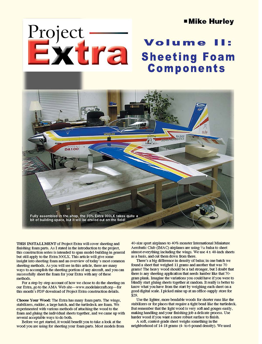
Project-Extra Sheeting Foam Components Volume II
THIS INSTALLMENT of Project Extra will cover sheeting and finishing foam parts. As stated in the introduction to the project, this construction series is intended to span model-building in general but still apply to the Extra 300LX. This article gives some insight into sheeting foam and an overview of today's most common sheeting methods. There are many ways to accomplish the sheeting portion of any aircraft, and you can successfully sheet the foam for your Extra with any of these methods.
For a step-by-step account of how we chose to do the sheeting on our Extra, go to the AMA Web site—www.modelaircraft.org—for this month's PDF download of Project Extra construction details.
Choose Your Wood
The Extra has many foam parts: the wings, stabilizers, rudder, a large hatch, and the turtledeck are foam. We experimented with various methods of attaching the wood to the foam and gluing the individual sheets together, and we came up with several acceptable ways to do both.
Before you start, examine the wood you are using for sheeting. Most models from 40-size sport airplanes to 40% IMAC airplanes are using 1/16-inch balsa to sheet almost everything, including the wings. We use 4 x 48-inch sheets as a basis and cut them down from there. There's a big difference in density of balsa; in one batch we found a sheet that weighed 11 grams and another that was 70 grams. The heavier wood should be a tad stronger, but I doubt any sheeting application needs lumber like that 70-gram plank. It is better to know what you have from the start by weighing each sheet on a good digital scale. I picked mine up at an office-supply store for $29.
Use the lighter, more bendable woods for shorter runs like the stabilizers or for places that require a tight bend like the turtledeck. But remember the light wood is very soft and gouges easily, making handling and finishing more delicate. Use harder wood if you want a more robust surface to finish. A soft, contest-grade sheet weighs in the neighborhood of 14–18 grams (4- to 6-pound density). We used planks that came in at 18–22 grams (6- to 8-pound density) for the wings, and we tried to avoid any wood exceeding 24–25 grams. Before any foam was glued, we weighed the individual parts and made sure the left and right sides were as near the same weight as possible.
Choose Your Glue
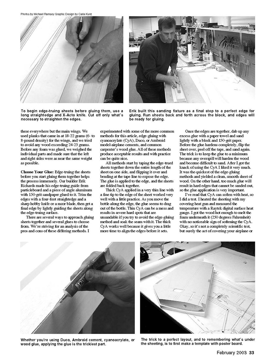
Edge-truing the sheets before you start gluing them together helps the process immensely. Our builder Erik Richards made his edge-truing guide from particleboard and a piece of angle aluminum with 150-grit sandpaper glued to it. Trim the edges with a four-foot straightedge and a sharp hobby knife or razor blade, then get a final edge by lightly guiding the sheets along the edge-truing surface.
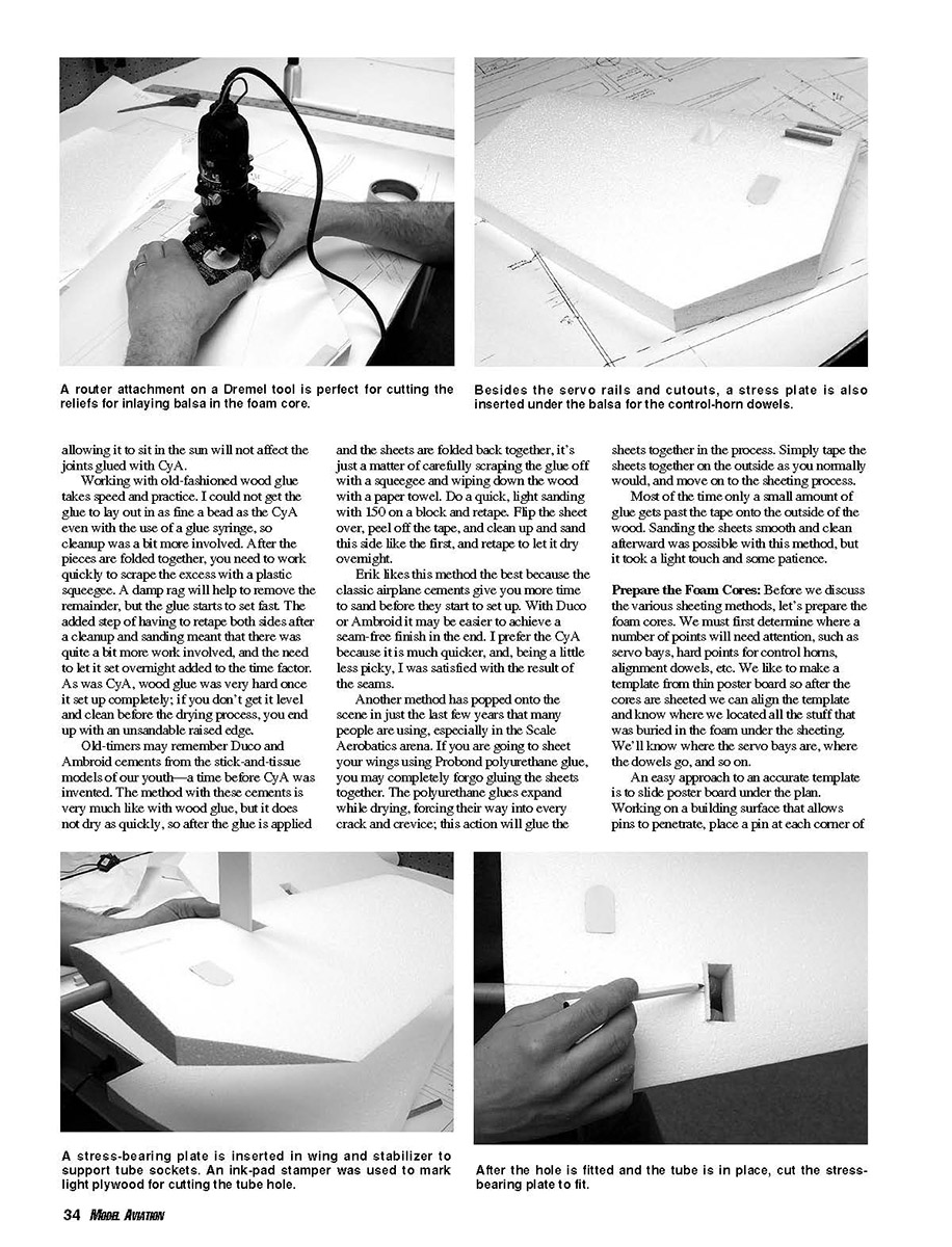
Whether you're using Duco, Ambroid cement, cyanoacrylate (CyA), or wood glue, applying the glue is the trickiest part. To begin edge-truing sheets before gluing them, use a long straightedge and an X-Acto knife. Cut off only what's necessary to straighten the edges. Run sheets back and forth across the sanding block or fixture as a final step to produce a perfect edge for gluing.
All methods start by taping the edge-trued sheets together down the entire length of the sheet on one side, flipping it over, and bending at the tape line to expose the edge. Apply the glue to the edge and fold the sheets back together.
- Thick CyA applied in a very thin line with a fine tip to the edge of the sheet worked very well with a little practice. As you move the bottle along the edge, the glue seems to draw out of the bottle. Thin CyA can be a mess and results in severe hard spots that are unsandable if you soak the seam with it. The thick CyA works well because it gives you a little more time to align the edges before it sets.
- Once the edges are together, dab up any excess glue with a paper towel and sand lightly with a block and 150-grit paper. Before the glue hardens completely, flip the sheet over, peel off the tape, and sand again. Keep the glue to a minimum because any overspill will harden the wood and become difficult to sand. CyA is the quickest of the edge-gluing methods and yields a clean, smooth sheet when used carefully.
- I tested CyA for heat sensitivity by heating the sheeting with a covering heat gun and measured the temperature with a Raytek digital surface heat gauge. I got the wood hot enough to melt the foam underneath it (about 250°F) with no noticeable sign of softening the CyA. Not a scientific test, but it indicates that typical covering or finishing temperatures (or allowing the airplane to sit in the sun) will not affect joints glued with CyA.
- Carpenter's (wood) glue requires speed and practice. I could not get the glue to lay out in as fine a bead as CyA even with a glue syringe, so cleanup was more involved. After folding the pieces together, quickly scrape the excess with a plastic squeegee and remove residue with a damp rag while the glue is still workable. Retape both sides after cleanup and sanding. Wood glue needs to set overnight and becomes very hard; if you don't get it level and clean before drying, you end up with an unsandable raised edge.
- Duco and Ambroid cements (classic model-airplane cements) behave similarly to wood glue but do not dry as quickly. After application and folding, carefully scrape glue off with a squeegee and wipe down the wood with a paper towel. Do a quick, light sanding with 150-grit on a block and retape. Flip the sheet over, peel off the tape, and clean up and sand the other side, then retape to let it set overnight. Erik prefers these cements because they give you more time to sand before they set, making it easier to achieve a seam-free finish. I prefer CyA for speed.
- ProBond polyurethane glue has become popular in recent years, especially in Scale Aerobatics. If you sheet wings using ProBond, you may forgo gluing the sheets together: the expanding glue forces its way into every crack and crevice, bonding the sheets as it expands. Simply tape the sheets together on the outside as you normally would, apply ProBond between the sheet and the core, and proceed to the sheeting process. Most of the time only a small amount of glue gets past the tape onto the outside of the wood. Sanding smooth afterward is possible, but it takes a light touch and some patience.
Prepare the Foam Cores
Before discussing sheeting methods, prepare the foam cores and locate points that need attention—servo bays, hard points for control horns, alignment dowels, and so on. We make a template from thin poster board so after the cores are sheeted we can align the template and know where everything buried in the foam is located.
An easy approach to an accurate template is to slide poster board under the plan. Working on a building surface that allows pins to penetrate, place a pin at each corner of the part and at each corner of the objects you want to locate. We wanted to bury dowel stress-bearing plates for the control-horn dowels and 1/4 x 3/8 x 2-1/4-inch spruce servo rails. Remove the poster board from under the plan and connect the dots (the holes you made with the pins). Later we'll use the template for marking and cutting the hinge lines, so be sure to add that to the template.
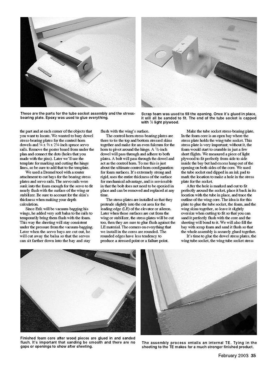
We used a Dremel tool with a router attachment to cut bays for the bearing stress plates and servo rails. The servo rails were sunk into the foam enough for the servo to fit nearly flush with the surface of the wing or stabilizer. Be sure to account for the skin's thickness when calculating depth.
Since Erik will be vacuum-bagging his wings, he added very soft balsa to the rails to temporarily bring them flush with the foam. This way the sheeting will stay consistent under the vacuum-bag pressure. Later when the servo bays are cut out, he will remove the balsa so the servos sit farther down into the bay and remain flush with the wing surface.
The control-horn stress-bearing plates tie the top and bottom skins together and provide an even fulcrum for the horn to pivot around the hinge. A 1/2-inch dowel will pass through and adhere to both plates. A bolt will pass through the dowel and act as the control horn. This configuration is extremely strong and rigid, uses the entire thickness of the surface for mechanical advantage, and is serviceable because the bolt can be removed and replaced without epoxying it in place.
Install the stress plates so they protrude slightly into the cut area for the leading edge (LE) of the elevator or aileron. Later when those surfaces are cut from the wing or stabilizer, the stress plates will be cut too, ensuring they glue flush against the LE material. Round the corners on everything you install in the cores; rounded edges reduce stress concentrations and failure points.
Make the tube-socket stress-bearing plate. In the foam core is an open bay where the stress plate holds the wing tube socket. This plate is very important; without it, the foam would start to crumble after only a few flights. We measured a piece of light plywood to fit perfectly from side to side inside the bay but left excess hanging out of the opening on both sides of the core. We used the tube socket end dipped in an ink pad to mark the location for a hole in the stress plate for the socket.
After the hole is marked and cut to fit perfectly around the socket, place it back in its location with the tube in place and trace the outline of the wing core. The idea is for the plate to glue the tube socket, the foam, and the wing skins together, so leave it slightly oversize when cutting so you can sand it perfectly flush with the core and the sheeting will bond to it. Fill the bay with scrap foam and sand it flush so the whole assembly is securely glued together.
Install the stress plates and servo rails into place before sheeting. In our foam cores, made by FlyingFoam.com, the channels for the servo wires are already cut into the main wing foam. For the stabilizers we'll use a 1/2-inch copper tube to cut a channel later. Cap the end of the tube socket with 1/8-inch light plywood and sand it flush. This will act as a tube stop; without it, the wing or stabilizer tube could migrate into the foam and cut as it goes.
We used epoxy to assemble everything. Other glues compatible with foam, such as carpenter's glue or ProBond polyurethane, are fine too. After the glue sets, sand the installed components flush to the core's surface. Make sure there is at least 3/8 inch of excess socket material extending from the root of the wing or stabilizer. You can see that the stress-plate bay has been filled with scrap foam, the servo rails and stress plates are in and flush, and that everything should glue nicely to the sheeting we are about to apply. The servo bays and holes for the control-horn dowels will be cut after the sheeting is in place.
On our wings and rudder we decided to bury our trailing edges (TEs) inside the sheeting. This method is structurally much stronger than butt-gluing the TE to the wing after it is sheeted. One of the worst enemies of large control surfaces, especially long ailerons, is flex. A flexible surface is more prone to failure because of flutter. We are striving for very light yet very rigid surfaces, and although it may be more work to build the TE into the wings, the strength advantage is well worth the effort.
The idea is simple: glue the TE to the bare foam and shape it to create an extension of the foam, then sheet over the whole assembly. The wings on the Extra were not designed to have completely sharp TEs, but the cores from FlyingFoam.com are cut oversized and go to a point so you can cut them to achieve your desired final result. We cut exactly 1 inch off the TE of the wings and rudder, added a half inch of balsa to create our TE, and sanded the balsa flush with the core. After the wings are sheeted your TEs will already be done; only a cursory sanding will be needed to true up the TE.
Now fit the wings and stabilizers to the fuselage and sand them to get a flush fit. Since you can't cut off the phenolic tube at this point, it may be a good idea to make a thick dummy root rib that will fit over the phenolic and fit tight against the fuselage side. Adjust by sanding the foam wing or stabilizer root until you get a nice, tight fit.
Sheeting Techniques
With a foam wing, strength is achieved by the shearing action between the sheeting and the foam. The thickness of the wing also plays a role. The density or strength of the sheeting itself is the least critical factor in wing strength. The method by which the sheeting is glued will, in large part, determine the wing's strength. A spar may help, but I have not found them necessary when the sheeting is done properly.
I don't claim to have all the answers. For most of us, the ultimate way to accomplish the task may be a combination of methods. Here are three methods for applying the sheeting to the foam: epoxy or ProBond with weights, contact cement, and vacuum-bagging. Erik will vacuum-bag his wings. You can find in-depth info about what we did during that process in the online construction manual; here we'll give a practical overview.
Contact Cement (spray) method
A close friend, Norm Cassella, a longtime builder with more than 60 completed 1/3-scale Lasers and countless other models, uses spray contact cement for all his foam sheeting. His models have proven themselves with countless hours baking in the sun—many are still flying weekly and in perfect condition after 10 years.
The trick is to use an industrial-grade spray glue. Some builders have used 3M #77 with less-than-satisfactory results. We have had great luck with 3M 08074 spray trim adhesive, available at automotive-parts stores. It won't melt the foam when applied correctly, it doesn't lift in hot weather, and it holds fast for years without drying out.
Contact glue is probably the quickest way to sheet foam, and although it is far less messy than other methods, it may not be the easiest. If the two pieces touch in the wrong spot, you could ruin a wing because they instantly adhere and will not separate without destroying one of the parts.
A good, flat table or work surface is essential. We used 5 x 3-foot slabs of machined marble—about as perfect as you can find without the expense of a machinist's table.
With contact glue, trial-fitting is the key. Start with the TE and roll the wing on the flat surface toward the LE. Mark the corners and double-check the marks. Spray the contact cement on both surfaces to be glued and let stand until tacky (usually about 10 minutes). Too much build-up takes longer to dry and may melt the foam, so don't overdo it. You want a medium, even coat. Getting the TE flat on the first contact is very important to obtain a straight TE. Tack down the TE, then roll the panel flat on the table to the LE. I use epoxy to adhere the end caps and edges and make sure they are glued well to any exposed sheeting; this helps prevent the sheeting from lifting at edges.
Weighted epoxy or ProBond method
Most modelers use the weighting method, and it works similarly with epoxy and polyurethane (ProBond). Trim your glued or taped sheets to fit in the shucks as tightly as you want. We leave roughly 1/4 inch overhang all the way around.
Erik likes to seal the wood before applying any epoxy so it does not soak into the wood too heavily. He prefers to use hairspray for its light weight and spray-on convenience, but Balsarite will seal the wood slightly better. Hairspray is ready to sand in a few minutes, whereas Balsarite must dry for several hours. Sand the hairsprayed surface with 320-grit paper on a foam block, and wipe it clean with a tack cloth or vacuum it.
Weigh the epoxy (or at least use a measuring vessel) to get the same amount on each wing panel. Spread it evenly with a plastic spreader or a credit card until the whole surface has a shine. Don't allow any significant buildup. Push any excess off onto waxed paper.
On your flat building surface, place the assembled wing core and skins into the shucks with the top of the wing down. Align the assembly and place a flat, true piece of 3/4-inch particleboard that spans the entire core on top to spread the weight. Most people use bricks or heavy blocks to weight the core. It takes at least 200 pounds or more on a wing this size to get a good, tight bond evenly across the wing surface. Add the weight and let the cores dry overnight.
Newsflash: While writing, Erik weighed the two sheeted wing panels complete with TEs, phenolic sockets installed, servo rails, and dowel plates. They are exactly the same weight (we had to weigh them in grams to verify). That's how accurate you can be when you pay attention to the details. Amazing!
Vacuum-bagging method
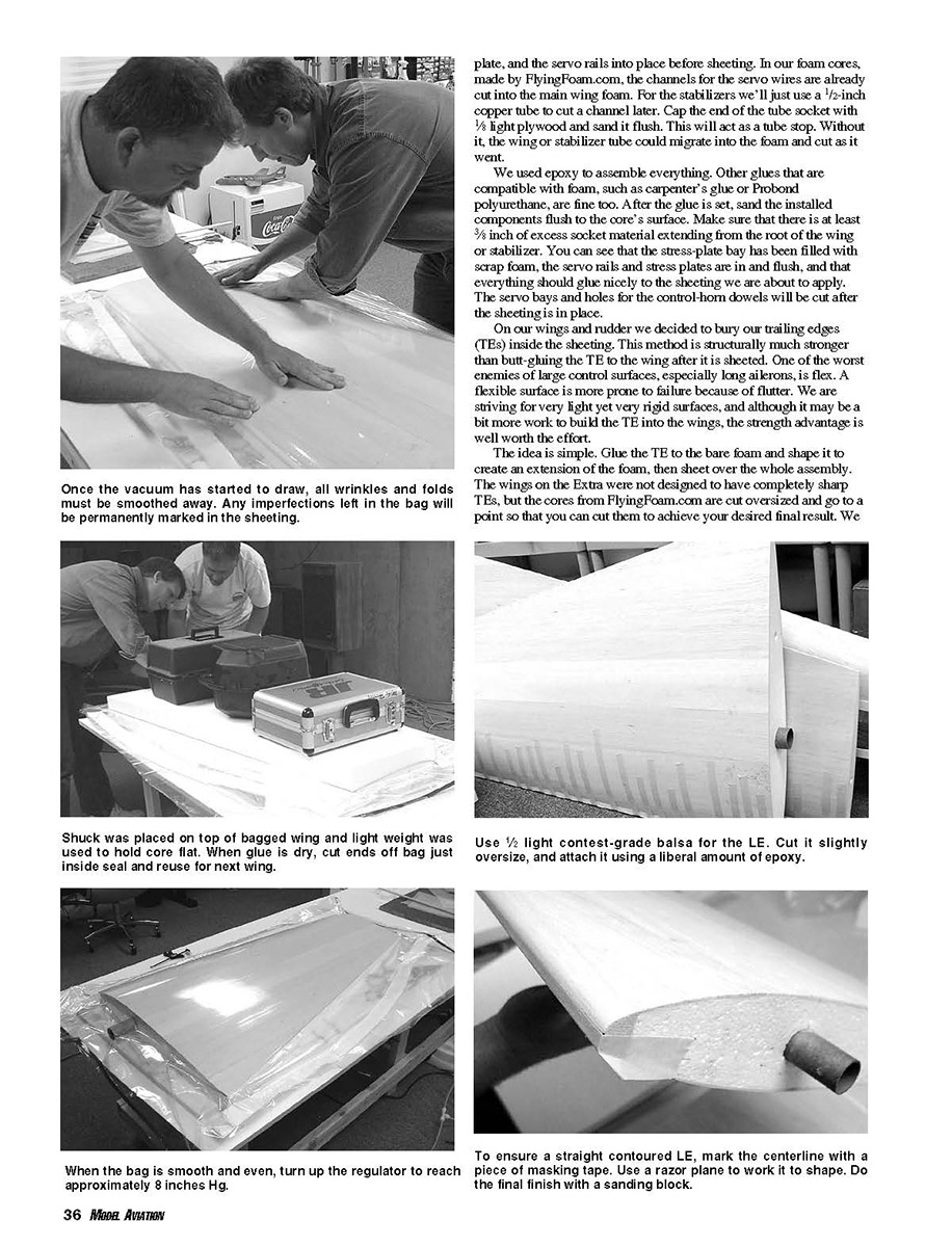
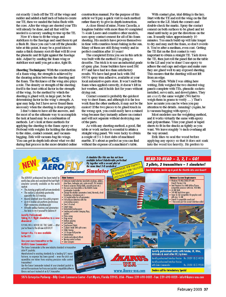
Erik wanted to use vacuum-bagging for our airplane. Vacuum-bagging places the wing in a plastic sleeve and seals it, allowing air to be pulled out with a vacuum pump to create uniform pressure around the entire wing assembly. At 8 inches Hg, the equivalent pressure would be about 1,800 pounds on the wing panel. The vacuum also tends to pull the glue farther into the porosity of the wood and the foam, creating a better bond with less glue.
This method requires special tools and materials. On average you can get started vacuum-bagging for roughly $300. The wing and skins are inside the plastic sleeve while the shucks are lightly weighted on the outside to hold everything in place. The vacuum bag also distributes pressure evenly across the surface, producing a consistent bond.
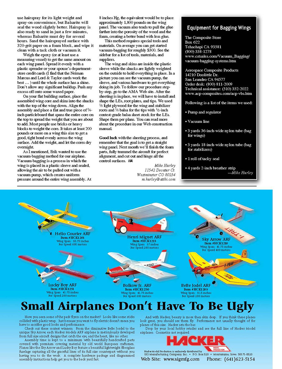
After the sheeting is in place, install and shape the LEs, root plates, and tips. We used 1/8-inch light plywood for the wing and stabilizer roots, 1/8-inch balsa for the tips, and 1/2-inch contest-grade balsa sheet stock for the LEs. Shape them per plans. You can read more about the procedure in our Web construction manual.
Good luck with the sheeting process, and remember the goal is to get a straight wing panel. Next month we'll finish the foam parts, fully trammel the aircraft for perfect alignment, and cut out and hinge all the control surfaces.
—Mike Hurley 11542 Decatur Ct. Westminster CO 80234 [email protected]
Equipment for Bagging Wings
The Composite Store Box 622 Tehachapi CA 93581 (800) 338-1278 www.cstales.com/Vacuum_Bagging/vacuum-bagging-systems.htm
Aerospace Composite Products 14210 Doolittle Dr. San Leandro CA 94577 Order desk: (800) 811-2009 Technical assistance: (510) 352-2022 www.acp-composites.com/acp-vbs.htm
Following is a list of the items we used:
- Pump and regulator
- Vacuum line
- 3 yards 36-inch-wide nylon tube (bag for wings)
- 3 yards 18-inch-wide nylon tube (bag for stabilizers)
- 1 roll of tacky seal
- 4 yards 2-inch breather strip
Transcribed from original scans by AI. Minor OCR errors may remain.

