
Volume IV: Controlling Systems
Mike Hurley
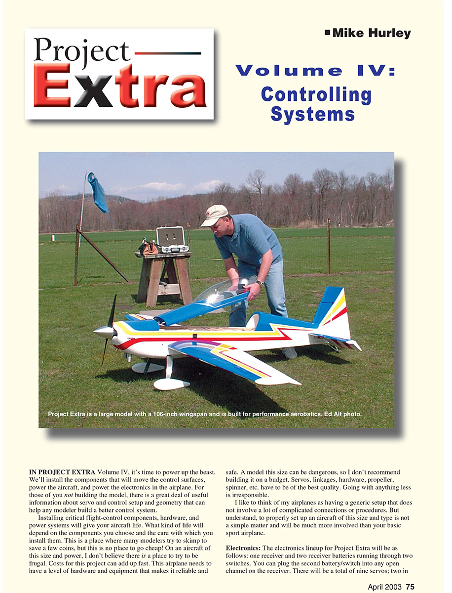
In Project Extra Volume IV, it's time to power up the beast. We'll install the components that will move the control surfaces, power the aircraft, and power the electronics in the airplane. For those not building the model, there's useful information here about servo and control setup and geometry that can help any modeler build a better control system.
Installing critical flight-control components, hardware, and power systems will give your aircraft life. What kind of life that is will depend on the components you choose and the care with which you install them. This is not the place to go cheap. On an aircraft of this size and power, costs can add up fast, but the airplane needs hardware and equipment that make it reliable and safe. A model this size can be dangerous, so I don't recommend building it on a budget. Servos, linkages, hardware, propeller, spinner, etc., should be of the best quality.
I like a generic setup that does not involve a lot of complicated connections or procedures. Still, properly setting up an aircraft of this size is more involved than your basic sport airplane.
Electronics
The electronics lineup for Project Extra will be:
- One receiver.
- Two receiver batteries running through two switches (the second battery/switch can be plugged into any open channel on the receiver).
- A total of nine servos:
- Two servos in each wing (four total).
- Two servos for the rudder (ganged together).
- One servo in each elevator half (two total).
- One throttle servo.
The wing servos will be mixed so differential is adjustable. The servos in each wing half will be matched with JR MatchBoxes. The rudder servos will be mixed through the radio with a multipoint mix.
You can save a few bucks by not buying exotic electronics. Multiple receivers, optical isolators, regulated batteries, and elaborate power-distribution systems are not necessary for this airplane. They do useful jobs, and I use many of those systems in larger models, but for this 35% competition airplane I prefer to keep it simple and concentrate on making the setup secure. I'll cover sophisticated electronics in a future column; you can also learn about multireceiver systems in the May 2002 Model Aviation Radio Control Scale Aerobatics column.
One thing that separates big airplanes from small ones is vibration. All components will experience harder vibration pulses, so electronics should be isolated as much as possible. Most receiver failures are caused by vibration, so proper isolation mounting helps protect your receiver. Even the material you use to fasten components is important: a heavy nylon tie transfers vibration more readily than a soft Velcro strap.
Erik Richards and I use Du-Bro foam rubber sold in hobby stores; it's the right density for vibration protection. A piece of 1/2-inch Du-Bro foam under the receiver, battery, or ignition module fastened with a Velcro strap works well. If you use nylon ties, wrap the entire component before tying it down. Avoid Velcro-fastening electronics directly to the model's wooden structure—that's taking a risk.
When choosing servos, stick with proven name brands for large scale performance airplanes. Futaba, Airtronics, and JR make excellent servos. For this project we chose JR DS8411 digital servos — rated at 155 in-oz torque and 0.16 sec/60° at 4.8 volts.
Servo Arm Geometry
Geometry and force/connection relationships are a big part of this phase. Understand how mechanical connections interact with the parts they link.
- Connections: For control rod ends we use ball links bolted to the servo arms. Ball links are simple and reliable, but because the connection is offset from the rotational center of the servo arm, forces tend to create twisting motion on the servo arm. If the servo arm twists, it places a side load on the control rod. To tame twist and ensure a solid connection, aluminum servo arms are a must when using ball links.
- Plastic arms: Heavy-duty plastic servo arms can work when used with a clevis supported on both sides of the arm, but they will twist when used in an offset environment (such as a ball link bolted to one side). For this project I used SWB aluminum arms pre-tapped for 4-40 bolts.
Mounting and orientation:
- The wings and horizontal stabilizers will have servos mounted in the bottom, vertically, nearly flush with the outer skin.
- A short control rod links the servo arm to a mild-steel bolt that acts as the control horn.
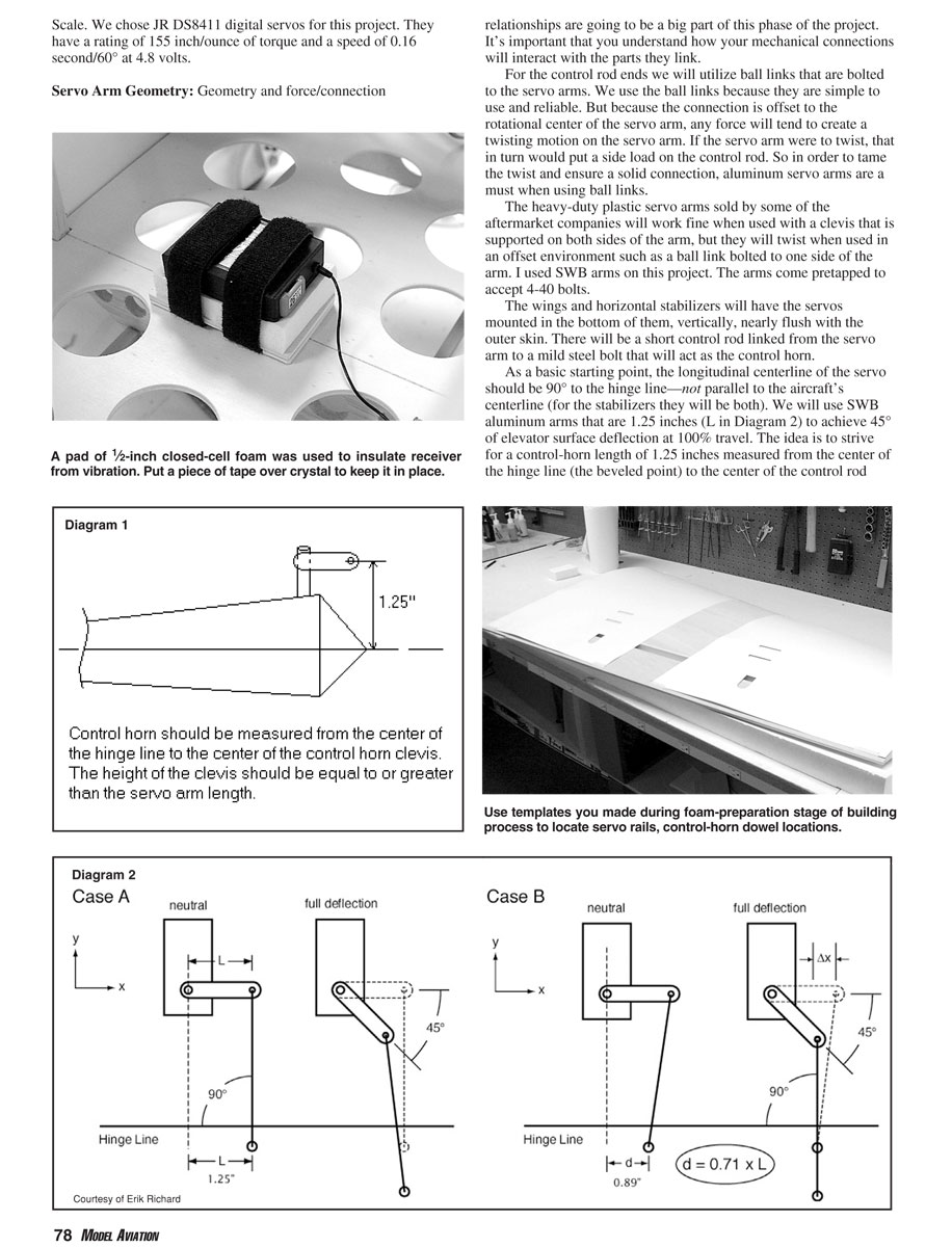
- As a basic starting point, the longitudinal centerline of the servo should be 90° to the hinge line (not parallel to the aircraft centerline). For stabilizers both are 90°.
Servo arm and control-horn sizing:
- We will use SWB aluminum arms that are 1.25 inches long (L in Diagram 2) to achieve 45° of elevator surface deflection at 100% travel.
- Aim for a control-horn length of 1.25 inches measured from the center of the hinge line (the beveled point) to the center of the control-rod clevis connection point (Diagram 1). This creates roughly a 1:1 ratio so you get needed deflection without compromising the servo's mechanical advantage.
- You can increase mechanical advantage by using a control horn longer than the servo arm, but you lose deflection. You can increase throw by using a servo arm longer than the control horn, but that decreases mechanical advantage. I find a 1:1 ratio works well when 45° deflection is desired.
Linkage plane and travel behavior:
- The servo rails mounted in the wings are approximately 2.5 inches, so position servos relative to the control horn when you map out the servo bays.
- Because the servo arm moves in an arc on a different plane from the control horn, the control rod angle changes as the servo travels. In Diagram 2, Case A shows the servo arm centered at 90° relative to the hinge line; as the arm travels (~45° at full travel), the x displacement decreases and the control rod angle moves away from 90°, making the motion nonlinear past ~45°. Mechanical force also decreases as the x distance decreases while aerodynamic loads increase with deflection.
- In Diagram 2, Case B, the control rod is 90° to the hinge line when the servo arm is at full deflection (45°). In this arrangement the force is greatest at full deflection where flight loads are likely highest and motion is closer to linear. We found that with a 1.25-inch servo arm the best location for the control horn is 0.89 inch from the centerline of the servo (d in Diagram 2).
For a software tool to design linkages, see the Linkage Design program from Envision Design: http://members.cox.net/evdesign/.
Installing the Dowels
Find the locations of the stress-bearing plates using the template you made for the wing cores. If you embedded servo rails under the skins as suggested during sheeting, locate them with your original templates. When determining a bay location, the dowel should just touch the beveled leading-edge stock—find the bay location in reference to the dowel position and mark it on the wing panels.
Cutting servo bays:
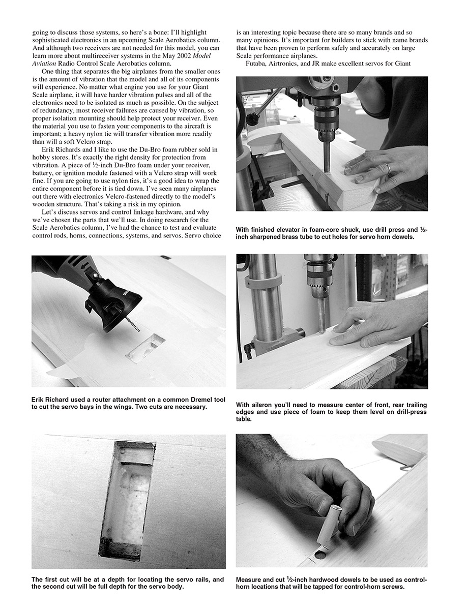
- Use a Dremel tool with a small router attachment to cut servo bays. Mask off the area to protect the wood. We cut the bays freehand, but for cleaner edges you can pin 1/4-inch square balsa sticks to act as a cutting fence.
- Decide how far to recess each servo. We recessed the JR DS8411 servos 3/8 inch. Make the cut to the depth of your servo's outside dimension; finish depth between the servo rails.
- If done correctly, the servo lead tunnels in the FlyingFoam.com wings should be accessible.
Dowel holes and installation:
- For control surfaces, use your template to find stress-plate locations. Tape the control surface into its original shuck and ensure center points (leading and trailing edges) are aligned so the dowels will be level and aligned correctly.
- CNC-cut wings from FlyingFoam.com are cut with dihedral built into the core (cut flat instead of on center), so cutting aileron dowel holes requires propping up the trailing edge to match the centerline height of the leading edge.
- Reamers work, but a sharpened 1/2-inch brass tube gives a smoother cut. The straightest hole comes from a drill press—set it to the slowest speed and work quickly to avoid heating and melting the foam. If foam melts, make a thick epoxy paste with microballoons to reset the dowels. Clean the cutting tube between cuts.
- Use good-quality hardwood dowels—maple is preferable, birch acceptable. Avoid pine or poplar. Insert a length of 1/2-inch dowel, mark and cut it; the dowel will follow the control surface contour. Avoid finish-sanding (hard to sand). Epoxy dowels in place.
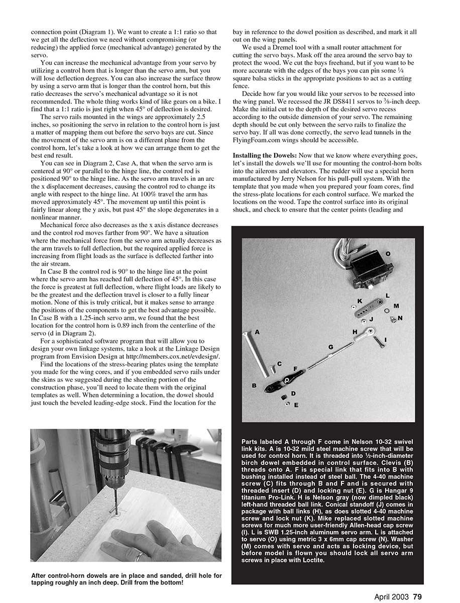
- Drill the dowels for your control-horn bolt. Tap the bolt into the dowel—do not drill completely through the dowel to exit the top of the control surface. Drill on the bottom side and use the proper drill size to tap for the thread. Drill and tap to about an inch depth.
Control Hardware
Attention to geometry separates a 60-size sport airplane from a Giant Scale airplane in terms of precision and reliability.
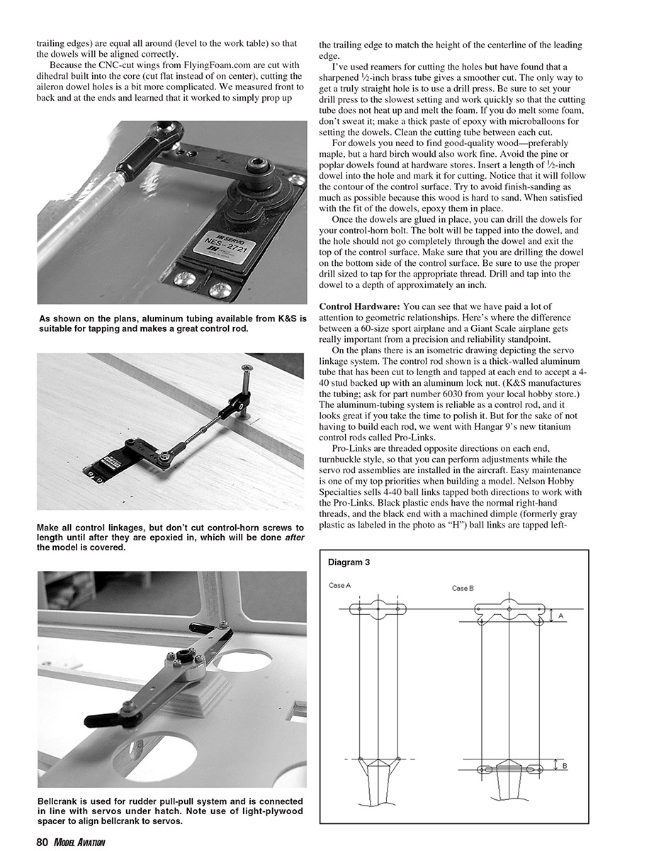
- Plans show an isometric drawing depicting the servo linkage system. The control rod shown is a thick-walled aluminum tube cut to length and tapped at each end to accept a 4-40 stud backed with an aluminum lock nut (K&S part number 6030).
- For convenience and easy adjustment, we used Hangar 9's Pro-Link titanium control rods. Pro-Links are threaded opposite directions on each end (turnbuckle style) so you can adjust while the rods are installed.
- Nelson Hobby Specialties sells 4-40 ball links tapped both directions to work with Pro-Links. Black plastic ends have normal right-hand threads; the black end with a machined dimple (formerly gray) is tapped left-hand so it threads onto Pro-Links properly.
Servo arm attachment:
- L is an SWB 1.25-inch aluminum servo arm. The arm (L) attaches to the servo (O) using a metric 3mm x 6mm cap screw (N). I replace factory Phillips screws with cap screws for ease of use. The washer (M) comes with the servo and acts as a locking device; use Loctite on servo arm screws before flight.
Assembly notes:
- We prefitted everything in the wings and made up control linkages and servo extensions. Control-horn bolts are not glued in until after covering; then we epoxy them into the dowels and use a Dremel cutoff wheel to remove the bolt head and trim to length.
Pull-Pull (Rudder)
We updated the rudder control from my prototype. The plans show a pull-pull rudder control; we used that with variations for a new-style rudder horn.
- Rudder setup:
- Two JR DS8411 servos ganged together and attached to a bellcrank.
- The bellcrank uses two Kevlar "Kev-cord" cables that attach to the rudder horn.
- Kev-cord and Kev-cord connectors are available from Aerospace Composite Products.
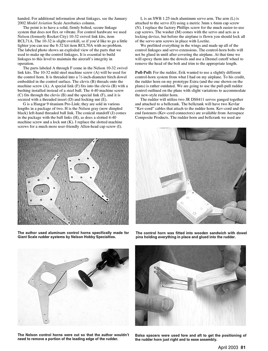
- The rudder horn and bellcrank used are from Nelson Hobby Specialties and are matched for this setup.
Geometry:
- Exact geometry is critical; improper geometry may allow cables to droop when the surface is deflected. Diagram 3 shows setup examples to ensure tight cables through the motion range.
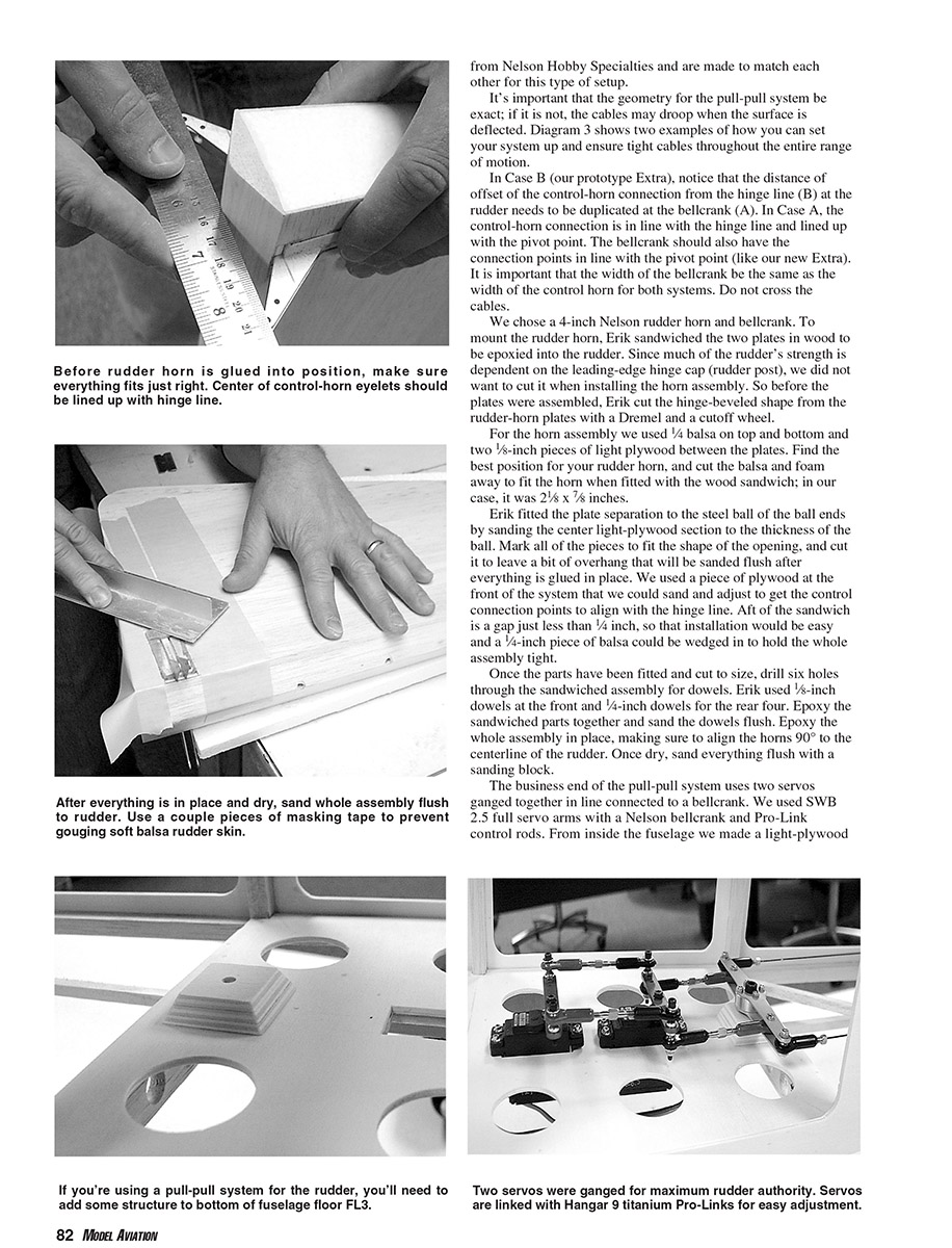
- In Case B (our prototype Extra), the control-horn connection offset from the hinge line at the rudder (B) must be duplicated at the bellcrank (A). In Case A, the control-horn connection is in line with the hinge line and pivot point; the bellcrank should likewise have connection points in line with its pivot. Ensure bellcrank width matches control-horn width. Do not cross the cables.
Horn and sandwich installation:
- We used a 4-inch Nelson rudder horn and bellcrank. To mount the rudder horn, Erik sandwiched the horn plates with wood to be epoxied into the rudder. Because much of the rudder's strength depends on the leading-edge hinge cap (rudder post), we avoided cutting it when installing the horn assembly.
- Before assembly, Erik cut the hinge-beveled shape from the rudder-horn plates with a Dremel and cutoff wheel.
- The horn assembly uses 1/4-inch balsa on top and bottom and two 1/8-inch pieces of light plywood between the plates. Find the best position, and cut balsa and foam away to fit the horn with the wood sandwich—in our case the sandwich was 2-1/2 x 7/8 inches.
- Fit the plate separation to the steel ball of the ball ends by sanding the center plywood to the thickness of the ball. Mark and cut pieces to leave a bit of overhang that will be sanded flush after gluing. Use a piece of plywood at the front of the system to sand and adjust to get control connection points aligned with the hinge line. Aft of the sandwich leave a gap just under 1/4 inch so a 1/4-inch piece of balsa can be wedged to hold the assembly tight.
- Drill six holes through the sandwiched assembly for dowels: we used 5/8-inch dowels at the front and 1/4-inch dowels for the rear four. Epoxy the sandwich together, sand dowels flush, then epoxy the whole assembly in place, aligning the horns 90° to the rudder centerline. Once dry, sand everything flush.
Bellcrank and servos:
- The pull-pull system uses two servos ganged in line connected to a bellcrank. We used SWB 2.5 full servo arms with a Nelson bellcrank and Pro-Link control rods.
- From inside the fuselage we made a light-plywood platform to raise the bellcrank to line up with the servo arm.
- Benefits of a bellcrank: it takes the load from tightly stretched cables off the servo grommets, output shaft, and bearings, and it enables correct geometry.
Final notes
I hope this gives you a better understanding of Giant Scale performance control systems. It would be impossible to document every building step in this magazine, so the basics are covered here, and there is much more on the AMA web site: www.modelaircraft.org/mag/index.htm — further details on control systems, fuel system, mounting the fiberglass, installing the engine, and lots of pictures in an easy-to-download PDF format.
Now that you've set up your airplane for its engine and flight controls, rip it back out and grab some sandpaper. It's time to start the covering and painting process — that's what we'll do in the next issue.
See you then.
Mike Hurley 11542 Decatur Ct. Westminster, CO 80234 [email protected]
Transcribed from original scans by AI. Minor OCR errors may remain.

