


Project Extra Volume VI: Setup and Flight Preparation
Mike Hurley
On a recent trip to the local flying field, one of the members had brought his latest project—shiny and new—ready for the initial test flight. I watched as he and his buddies began to go over the aircraft, checking this and checking that. They adjusted the servo throw, and two or three guys started to remove pieces from the airplane while others made adjustments. Soon there was a large crowd around the airplane. After some time it was determined that the owner needed to take the airplane back home for some finishing before it could be flown.
Sound familiar? You might have seen this happen at one time or another. This particular flier was not a novice pilot; he had years of experience and was considered by many to be one of the best pilots in the area. Yet he came to the field with the intention of flying an unprepared and untested aircraft with the idea that a few last-minute items would be no big deal once he was there. Come on! Don’t go to the field and install your servos! Make all of your last-minute adjustments in the workshop and be 100% prepared to fly when you leave your shop.
It’s important to fully finish and ready any aircraft before it goes to the field, but it is especially important with an aircraft the size of the 35% Extra 300LX. If you need the help of others in your club, ask those you know have the experience you need rather than taking the chance on whoever may be present the day you go out for the initial flight. Get the help you need and test every aspect of your airplane, then you can be confident that you’re ready when you finally do get to that first flight.
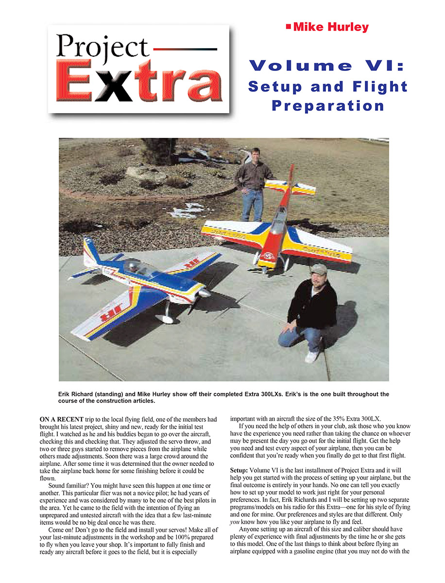
Setup: Volume VI is the last installment of Project Extra and it will help you get started with the process of setting up your airplane, but the final outcome is entirely in your hands. No one can tell you exactly how to set up your model to work just right for your personal preferences. In fact, Erik Richards and I will be setting up two separate programs/models on his radio for this Extra—one for his style of flying and one for mine. Our preferences and styles are that different. Only you know how you like your airplane to fly and feel.
Anyone setting up an aircraft of this size and caliber should have plenty of experience with final adjustments by the time he or she gets to this model. One of the last things to think about before flying an airplane equipped with a gasoline engine (that you may not do with smaller models) is to Loctite all of the metal-to-metal hardware that does not need field assembly. Use thread locker made for hand-tool removal (usually the blue formula—check the label).
I’m assuming you know about basic preflight and finishing procedures for a new aircraft: installing, charging, and checking batteries; sealing any exposed wood in the engine compartment; range checking; and other standard modeling procedures, so I won’t detail those steps. But you know as an experienced modeler that all of those things are important for a successful aircraft. Again, if you have questions, get help from someone who has the experience. There’s a good article on range checking at http://horizon.hobbyshopnow.com/articles/1079.asp.
In this issue we’ll look at basic programming for the Extra so that all servos work together and you have an idea of how to set up a large aerobatic airplane. I’ll give guidelines for balance and control throws and discuss standard trimming for a precision aircraft. I’ll use the JR 10X radio for examples because that’s what I use, but you can do most of these things with any modern computer radio. Refer to your transmitter’s instruction manual, and remember that many functions that perform the same tasks are referred to differently by manufacturers. Each of these topics could encompass an entire article, so I’ll be limited to the basics. You'll want to expand the information on your own with experimentation, practice, and help from friends. Another useful article is at http://horizon.hobbyshopnow.com/articles/1169.asp (click the PDF).
Mixing
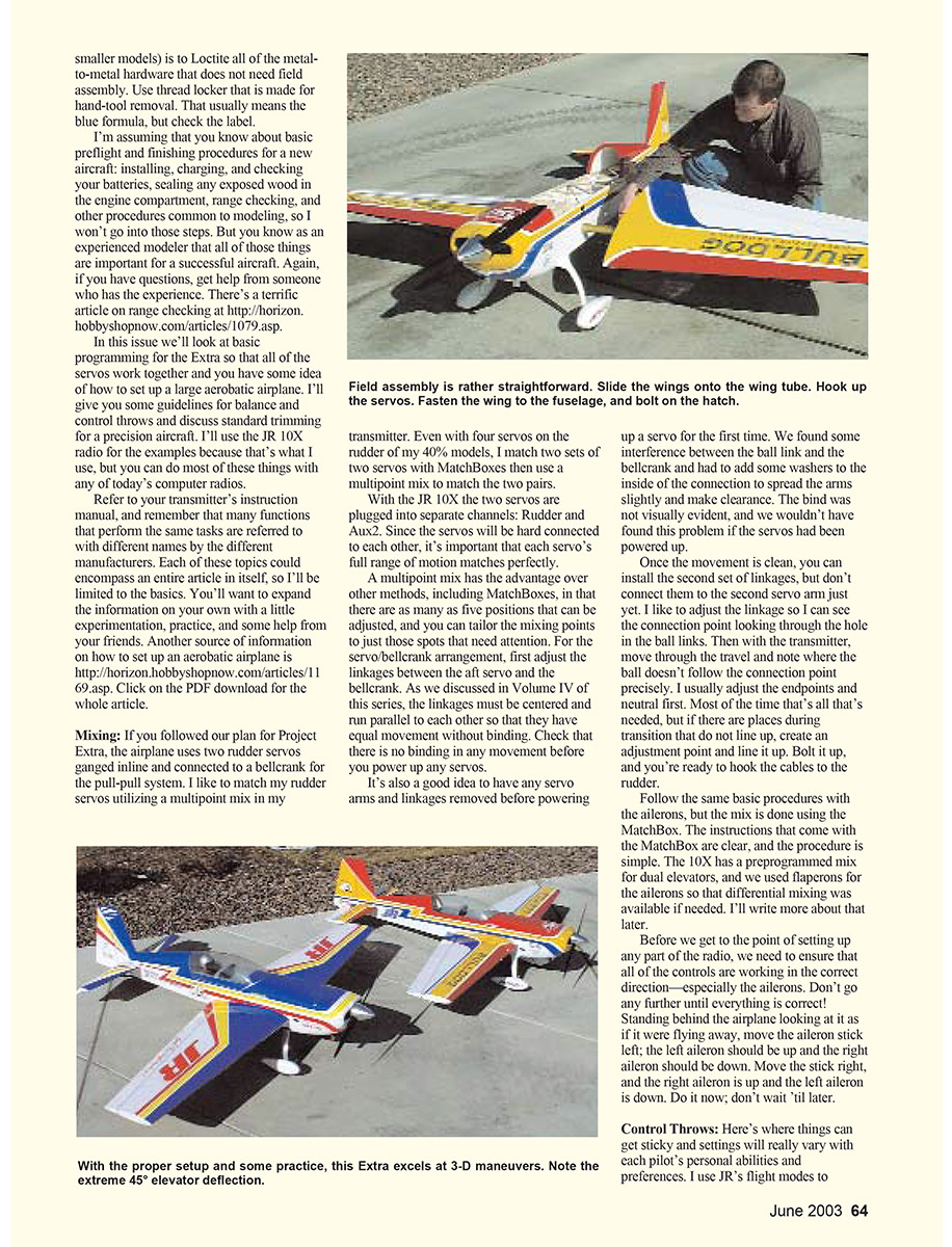
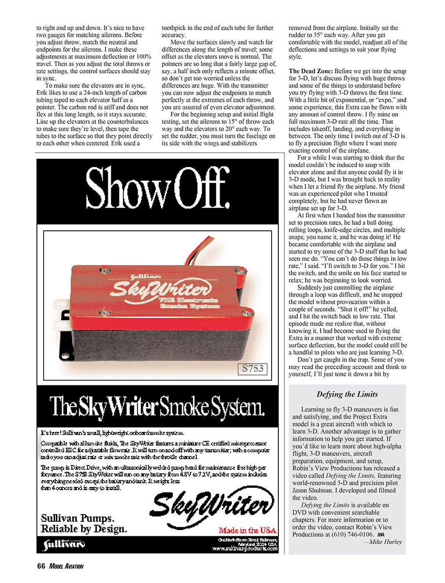
If you followed our Project Extra plan, the airplane uses two rudder servos ganged inline and connected to a bellcrank for a pull-pull system. I like to match rudder servos using a multipoint mix in my transmitter. Even with four servos on the rudder of my 40% models, I match two sets of two servos with MatchBoxes and then use a multipoint mix to match the two pairs.
With the JR 10X the two servos are plugged into separate channels: Rudder and Aux2. Since the servos will be mechanically connected, it's important that each servo's full range of motion matches perfectly. A multipoint mix has the advantage over other methods (including MatchBoxes) in that there are as many as five positions that can be adjusted, so you can tailor the mixing points to the spots that need attention.
For the servo/bellcrank arrangement, first adjust the linkages between the aft servo and the bellcrank. As discussed in Volume IV, the linkages must be centered and run parallel to each other so they have equal movement without binding. Check that there is no binding in any movement before you power up any servos.
It's a good idea to have servo arms and linkages removed before powering up a servo for the first time. We found some interference between the ball link and the bellcrank and had to add washers to the inside of the connection to spread the arms slightly and create clearance. The bind was not visually evident, and we wouldn't have found this problem if the servos had been powered up.
Once movement is clean, install the second set of linkages but don't connect them to the second servo arm yet. I adjust the linkage so I can see the connection point through the hole in the ball links. Then, with the transmitter, move through the travel and note where the ball doesn't follow the connection point precisely. I usually adjust endpoints and notch them first. Most of the time that's all that's needed, but if there are places during travel that do not line up, create an adjustment point and line it up. Bolt it up, and you're ready to hook the cables to the rudder.
Follow the same basic procedures with the ailerons, but the mix is done using the MatchBox. The MatchBox instructions are clear and the procedure is simple. The 10X has a preprogrammed mix for dual elevators, and we used flaperons for the ailerons so that differential mixing was available if needed.
Before setting up any radio programming, ensure all controls work in the correct direction—especially the ailerons. Don't go further until everything is correct. Standing behind the airplane looking at it as if it were flying away, move the aileron stick left; the left aileron should go up and the right aileron down. Move the stick right and the opposite should occur. Do it now; don't wait until later.
Control Throws
Control throw settings vary by pilot preference and ability. I use JR's flight modes to control all my rates with a single switch; flight modes help me avoid confusion. You should set up your radio in the way you’re most comfortable. After you get comfortable with the airplane, you can experiment with new switches and rate types, such as flight modes. If you're fairly new to 3-D, be sure to have a quick and easy way to escape the 3-D setting, and never fly a new model without an option for a reduced-rate elevator.
For starters, set up the Extra with two sets of control rates: a standard rate for everyday flying (later optimized for precision) and a maximum control-throw setting for 3-D.
Setting surface deflection is critical. For control setup I use CRC Throw Meters to tell me, in degrees, exactly where control surfaces are set. The CRC gauges are available from Central Hobbies at www.centralhobbies.com/.
Match aileron throw left to right and up and down. Two gauges help for matching ailerons. Before you adjust throws, match the neutral and endpoints for the ailerons—make these adjustments at maximum deflection or 100% travel. As you adjust total throws or rate settings, the control surfaces should stay in sync.
To sync elevators, Erik likes to use a 24-inch piece of carbon tubing taped to each elevator half as a pointer. The rod is stiff, so it stays accurate. Line up the elevators at the counterbalances to make sure they're level, then tape the tubes so they point directly to each other when centered. Erik used a toothpick in the end of each tube for further accuracy.
Move the surfaces slowly and watch for differences along the length of travel; some offset as the elevators move is normal. The pointers are long enough that a fairly large physical gap can still represent a minute offset, so don't worry unless differences are large. With the transmitter you can now adjust endpoints to match perfectly at extremes of each throw, ensuring even elevator adjustment.
Initial recommended throws for first flights:
- Ailerons: 15° each way
- Elevators: 20° each way
- Rudder: 35° each way (set with fuselage on its side and wings/stabilizers removed)
After you get comfortable with the model, readjust deflections and settings to suit your flying style.
The Dead Zone
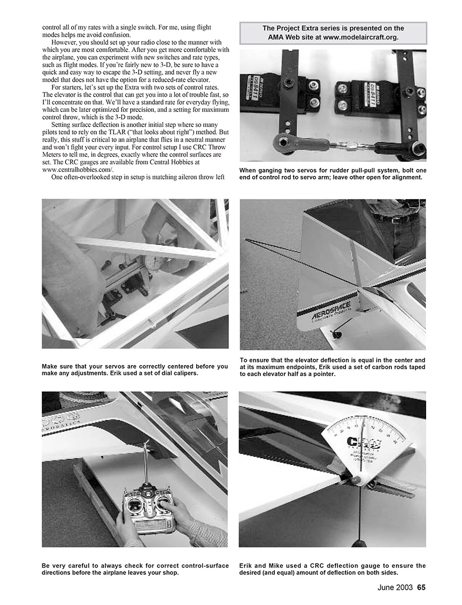
Before diving into 3-D setup, understand the dead zone. With a bit of exponential (expo) and experience, this Extra can be flown with very large throws. I fly mine on full maximum 3-D rate all the time—takeoff, landing, and everything in between. The only time I switch out of 3-D is to fly a precision routine.
I once thought the model couldn't be induced to snap with elevator alone and that anyone could fly it in 3-D mode. I was brought back to reality when a trusted, experienced friend who had never flown a 3-D‑setup took the transmitter. He flew beautifully in precision rates, then I switched to 3-D. Suddenly controlling a loop was difficult and he snapped the model almost immediately. He yelled, “Shut it off!” and I switched back to low rate.
Don't get caught in the trap. Some may think, “I'll just tone it down a bit by reducing the control throw and work up to more throw as I get comfortable.” That's exactly what can get you into trouble. The secret to entering and exiting 3-D is having the pitch authority to power past a stalled attitude and hold it with massive surfaces, deflection, and prop blast. If you lower surface deflection too much, the airplane won't have the required pitch authority and will stall. I call that lowered surface deflection the dead zone: too low for 3-D and too high for precision control. The dead zone will get you into trouble quickly.
Defying the Limits
Learning 3-D is fun and satisfying, and the Project Extra model is a great aircraft with which to learn. If you'd like more on high-alpha flight, 3-D maneuvers, aircraft preparation, equipment, and setup, Robin's View Productions released a video called Defying the Limits, featuring world-renowned 3-D and precision pilot Jason Shulman. I developed and filmed the video.
Defying the Limits is available on DVD with searchable chapters. For more information or to order, contact Robin's View Productions at (610) 746-0106.
Flying 3-D
When flying the model, be committed to getting into and out of a high-alpha (HA) attitude. It's important to have enough airspeed or power to transition into a high angle of attack. People get into trouble when they move too slowly into the transition or don't use enough elevator deflection or engine power.
You don't necessarily need higher forward airspeed for 3-D, but if speed is low you must use engine power to move the tail into position. You can slow the model to a stall as long as you keep inducing power to keep the tail below the airplane; you can then transition into a hover with no forward airspeed. Conversely, you can transition into HA with power off if you maintain speed to pop the model into position, but once in position you must power up to hold altitude.
Learning to fly into and out of HA safely is the beginning of 3-D; it takes finesse. If you're not getting it right, the aircraft will let you know with a wing drop or a snap.
My recommendation—even for experienced pilots—is to start slow and use the rate switch. Have enough expo dialed in to keep the airplane controllable and switch into 3-D only to execute a specific 3-D maneuver, then switch back to low rate to fly out.
Recommended 3-D deflections and dead zone:
- Elevator: 45° for 3-D. Dead zone: 27–37° (avoid).
- Ailerons: 25–30° for 3-D.
- Rudder: 45° for 3-D.
There is no dead zone for rudder or ailerons.
If you must significantly reduce travel on your radio to get ailerons down to 30°, move the control-rod mounting position on the servo arm inboard toward the output shaft until you get the desired deflection with the radio at 100%.
Exponential
Expo allows nonlinear stick response relative to servo output. Pilots use expo to soften stick feel around neutral, especially with large surface deflection. Expo moves a portion of servo travel farther out in the stick travel so the servo moves less near center and more exponentially toward full travel.
Note: JR radios use positive expo to soften the neutral area, while Futaba uses a negative value for the same effect—read your manual.
I can't set your expo for you, so you must experiment. Change one setting at a time. These are my settings at max 3-D deflection:
- 3-D expo: aileron +50%, elevator +55%, rudder +30%
- Precision expo: aileron +30%, elevator +30%, rudder +40%
I use more rudder expo in precision to smooth rudder wobble. Expo can greatly smooth center-stick control while preserving large deflection when needed—be careful not to numb the center entirely.
Balance
The center of gravity (CG) shown on the plans is conservative, about 32% of chord at the mean aerodynamic center (MAC). I fly my airplane at this forward position; it works well for both 3-D and precision. It's safe to locate the CG anywhere between F3 and the forward edge of the wing tube socket. Within limits, CG location can be a personal preference: many top pilots fly forward for precision and move the CG aft for freestyle.
A rear-biased CG is not required for 3-D. A rearward CG can slightly enhance some 3-D maneuvers, but performance often suffers in other attitudes. I prefer to sacrifice a small amount of 3-D performance to keep the aircraft’s integrity intact; with practice I can still perform many 3-D maneuvers.
Trimming
Trimming for neutral flight is the difference between a model that flies well and one you fight to keep on track. Trimming is also commonly overlooked in competition-readying. It takes time: I spent almost 100 flights getting a competition airplane where I wanted it. The plane wasn’t problematic—it had high potential and that’s why I spent the time to get it nearly perfect.
Look for the ability to fly precision up-and-down lines, 45s, and loops without continuous stick input. Many good trimming procedures and charts exist; I’d be doing you a disservice to condense them too much. You can download a chart from the National Society of Radio Controlled Aerobatics at www.nsra.org/trimA.htm. While you’re there, explore the site; NSRA leads the way in precision aerobatics.
Common Mixes
Most Scale Aerobatics (SA) airplanes have some unwanted coupling to the rudder. Ideally, rudder movement imparts yaw only, but many scale aircraft also induce roll and/or pitch. To achieve precision, create mixes to trim out those effects. After you’re comfortable with the airplane, you can add these trimming mixes.
Check rudder coupling by flying the airplane in knife-edge. Set the mix by flying at an even medium speed with only enough rudder to sustain level knife-edge flight. Many modern radios have special mixes for this trimming procedure. JR computers from the 662 up to the 10X include this feature.
Rudder is the master channel. Aileron is slaved for roll and elevator for pitch. Mix amounts depend on your model and dynamic forces like atmospheric density, balance, airspeed, and servo power. No mix will be 100% foolproof; variations between models and flights are normal.
Left-rudder and right-rudder mixes often differ, so trim them one step at a time. Our Extra does not have roll coupling, but it tucks slightly, so I use 10% up-elevator mixed for left and right rudder. That number would decrease with a more rearward balance. To be conservative, start at approximately 5% up if it tucks toward the gear or down if it pulls to the canopy, then adjust as needed.
I like to put the mix on a switch so it can be defeated if necessary—useful during rolling maneuvers like slow rolls or rolling circles—although I tend to leave the switch on.
More Mixes
Other common mixes for 3-D aircraft include a throttle curve and aileron differential. I don’t use either on my airplane, but here’s why they’re used:
- Throttle curve: smooths engine power feel across stick range. Carburetor butterfly position doesn’t translate linearly to rpm, so most power change comes at the lower end of stick movement. A curve can give a more even feel and help with torque rolling if hovering rpm is touchy. I used throttle curves at sea level, but after moving to high altitude in Colorado I removed them.
- Aileron differential: evens out drag on each wing during rolling. The down aileron usually creates more drag (adverse yaw). Differential programs reduce the down aileron travel to balance yaw during rolls. Visualizing this can be tricky; it often comes down to experimentation until the roll looks right. Historically, designers adjusted the aileron hinge line to change differential—thankfully we have computers now. Our Extra has an axial roll, so I have no differential programmed.
Ready to Fly!
If you’ve followed Project Extra through the building process, you’re probably just putting the last drops of Loctite on your bolts and checking throw directions one final time before heading to the field for first flights.
Who would have imagined five years ago when I started dreaming about the type of scale aerobatic model I wanted that it would turn into a major project to share with the modeling community? I hope you come away from this series with new knowledge or ideas about your own modeling experiences. And if you come away with a new airplane, even better!
It’s been incredibly gratifying to read so many letters and emails from AMA members who have followed and enjoyed the series. Documenting this construction would not have been possible without Erik Richards’ tireless effort and perfectionism. When we started this project, Erik’s wife Angela was newly expecting their first child. Erik’s daughter Julia is a year old now! Throughout it all, Erik’s commitment to the project has been unwavering.
Oh, don’t think for a minute that he’s going to have time to sit around at home with his family now. We have plenty more ideas and projects ready to start, and we can stay busy for a long, long time.
— Mike Hurley
11542 Decatur Ct Westminster, CO 80234 [email protected]
Transcribed from original scans by AI. Minor OCR errors may remain.

