
PT-3
Frank Baker
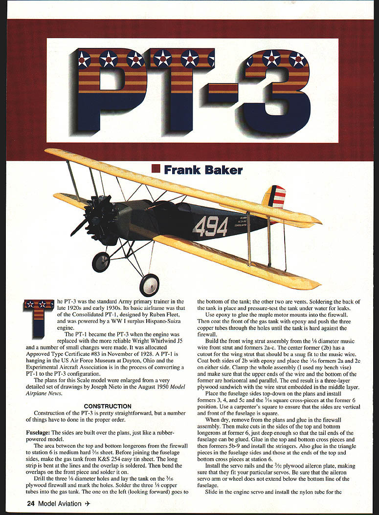
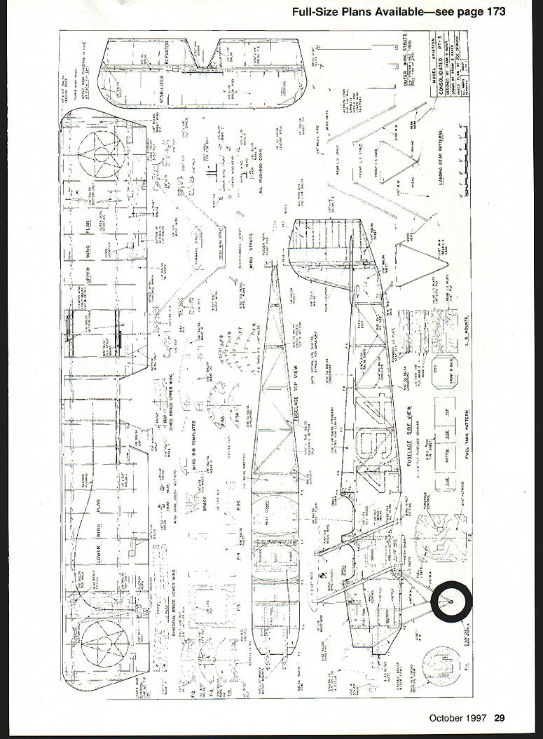
The PT-3 was the standard Army primary trainer in the late 1920s and early 1930s. Its basic airframe was that of the Consolidated PT-1, designed by Ruben Fleet, originally powered by a World War I surplus Hispano-Suiza engine. The PT-1 became the PT-3 when the engine was replaced with the more reliable Wright J-5 Whirlwind and a number of small changes were made. It was allocated Approved Type Certificate #83 in November 1928. A PT-1 is hanging in the U.S. Air Force Museum at Dayton, Ohio, and the Experimental Aircraft Association is in the process of converting a PT-1 to the PT-3 configuration.
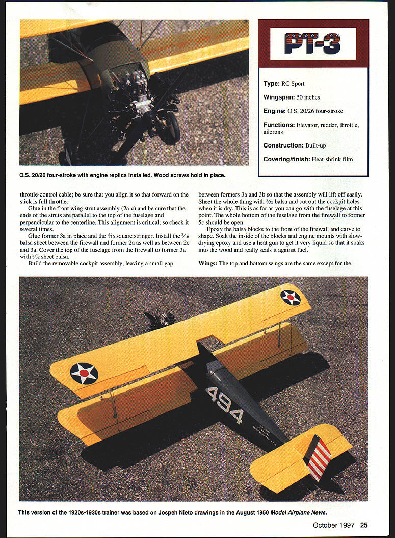
The plans for this scale model were enlarged from a very detailed set of drawings by Joseph Nieto in the August 1950 Model Airplane News.
Construction
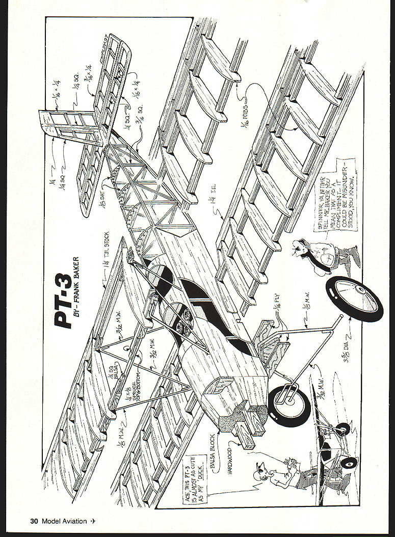
Construction of the PT-3 is straightforward, but many operations must be done in the proper sequence.
Fuselage
Build the fuselage sides over the plans, as you would for a rubber-powered model.
- To the line between the top and bottom longerons from the firewall to station 6, attach medium-hard 3/16" sheet.
- Before joining the fuselage sides, make the gas tank from K&S 254 easy tin sheet. Bend the long strip at the lines, solder the overlap, then bend and solder the overlaps on the front piece.
- Drill three 1/8" diameter holes and solder three 1/8" copper tubes into the gas tank. The left tube (looking forward) is the feed tube and should reach the bottom of the tank; the other two are vents. Solder the back of the tank in place and pressure-test the tank under water for leaks.
- Epoxy the maple motor mounts into the firewall. Coat the front of the gas tank with epoxy and push the three copper tubes through the firewall holes until the tank is hard against the firewall.
Front wing strut assembly:
- Build the front wing strut assembly from 1/8" music wire and formers 2a–2c. The center former (2b) has a cutout for the wire and should be a snug fit.
- Coat both sides of former 2b with epoxy, place 1/16" formers 2a and 2c on either side, and clamp. Ensure the upper ends of the wire and the bottom of the former are horizontal and parallel. The result is a three-layer plywood sandwich with the wire embedded.
Assemble fuselage structure:
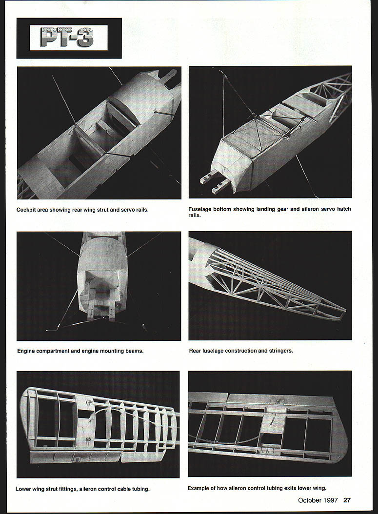
- Place the fuselage sides top-down on the plans and install formers 3, 4, and 5c and the 1/16" square cross-pieces at former 6. Use a carpenter’s square to ensure sides are vertical and the front is square.
- When dry, remove from the plans and glue in the firewall assembly. Cut slots in the sides of the top and bottom longerons at former 6, just deep enough so the tail ends of the fuselage can be glued. Glue in the top and bottom cross pieces, then formers 5b–9 and install the stringers. Glue in the triangular pieces in the fuselage sides and those at the ends of the top and bottom cross pieces at station 6.
- Install servo rails and the 3/32" plywood aileron plate, making sure they fit your servos. Ensure the aileron servo arm or wheel does not extend below the bottom line of the fuselage.
- Slide in the engine screw and install the nylon tube for the throttle-control cable. Align the throttle so forward stick equals full throttle.
- Glue the front wing strut assembly (2a–2c) in place, making sure the ends of the struts are parallel to the top fuselage and perpendicular to the centerline; alignment is critical—check several times.
- Glue former 3a and the 3/32" square stringer. Install 1/16" balsa sheet between the firewall and former 2a, and between 2c and 3a.
- Cover the top fuselage from the firewall to former 3a with 3/32" sheet balsa. Build a removable cockpit assembly, leaving a small gap between formers 3a and 3b so the assembly will lift off easily. Sheet the cockpit with 1/2" balsa and cut out the cockpit openings. Dry-fit as far as possible.
- The bottom fuselage at the firewall and former 5c should open. Epoxy balsa blocks to the front firewall and carve to shape. Soak the inside blocks and engine mounts with slow-drying epoxy; warming the epoxy with a heat gun makes it penetrate and seal against fuel.
Wings
The top and bottom wings are essentially the same except for center-section cutouts in the top wing for the cabane struts and the aileron control exits; only the bottom wing has nylon tubes and cables to drive the ailerons.
- Wing spars are laminated: outer laminations and a balsa core. The front spar includes a 1/16" square member.
- When building the lower wing, install but do not glue the ribs adjacent to the fuselage; you may need to adjust them later. Note the bottom of each aileron is a piece of 1/16" sheet balsa. Use a small plane to trim the two balsa false spars at the ailerons to match the rib contour.
- Once the basic wings are complete, cut them at the dihedral breaks and glue in the plywood dihedral braces.
- Fabricate .015" aluminum wing strut brackets and bend them per the plans. Place a piece of 3/16" plywood in the open gap and use a drill press to drill the 3/32" bolt hole.
- File two small notches on each side of the horizontal rails of the brackets. These brackets are held to the wing spars by short pieces of copper wire that wrap around the spar and bracket and are twisted together inside the wing. Clip the ends, leaving about 2–3 turns, and fold the ends down. Install the correct bracket in its location and glue 1/16" balsa sheet around each bracket to anchor the covering.
- Install removable-pin hinges (for example, Klett-type) in the wing and ailerons so ailerons can be removed or covered easily. Glue 1/16" balsa plates in the bottom of the wing for the aileron push-cable exits.
Nylon tube for aileron cables:
- I used Hobby Lobby bulk pack #HLH 805 nylon tube and cable. The tubing arrives coiled; cut the tube a few inches longer than needed and insert a 1/16" length of music wire. Heat evenly with a heat gun and let cool; then remove the wire. Repeat carefully if necessary to straighten the tube.
- Use a 9/64" drill bit to cut the holes in the bottom wing ribs for the cable. The holes in the last two ribs before the bottom plate should be above the front spar so the tube exits through the balsa plate at an angle. Make the holes incrementally higher as you approach these ribs for a smooth path.
- Bolt the aileron horns to a 1/8" plywood plate in each aileron and install the ailerons. Run the cable through the nylon tube and tape each end to the outer end of the aileron horn to set the tube angle. Once aligned, glue the nylon tube in place with clear silicone RTV.
Repeat glue-in of front wing strut assembly:
- Glue the front wing strut assembly (2a–2c) and confirm ends are parallel to the top of the fuselage and perpendicular to the centerline. Alignment is critical—check multiple times.
Specifications
- Type: RC Sport
- Wingspan: 50 inches
- Engine: O.S. 20/26 four-stroke
- Functions: Elevator, rudder, throttle, ailerons
- Construction: Built-up
- Covering/finish: Heat-shrink film
Completing the Fuselage and Landing Gear
- Fabricate the four landing-gear components. Bend landing-gear wires at plan-indicated points and directions. Use clothespins or pliers to rough-assemble wires and plywood parts.
- Place the components in the fuselage and confirm bends and hook-ups are correct. Use the same laminating process as the front wing strut to epoxy plywood and music wire together.
- Slide the plywood sandwich into the fuselage and check the wire matches. Adjust by clamping and bending in a vise if necessary. Make the rear wing strut assembly in the same manner. This free-flight technique yields a very strong assembly.
- Cut rectangular slots in the bottom of the fuselage for the lower wing spars and the aileron control nylon tube. Slip in the lower wing and check alignment and a 1-1/2° incidence. Use a carpenter’s square to ensure the leading edges of the wing are perpendicular to the fuselage sides. If trimming is required, glue shims to the fuselage to achieve proper alignment. Glue the lower wing butt ribs, leaving about 1/2" clearance from the fuselage.
- Decide whether to glue the lower wing before covering: covering the lower wing and fuselage sides before gluing prevents oil from the engine from getting into the butt ribs and fuselage sides.
- Glue the wing to the fuselage using a slow-drying glue so you can check alignment and incidence again.
- Install landing gear: glue the rear landing-gear strut sandwich to the front wing spar and fuselage and clamp. Check that the airplane sits level and the axles are perpendicular to the fuselage centerline. Glue the front landing-gear strut assembly to the firewall; this forms the third member of the sandwich.
- When glue is dry, bend the ends of the front strut to match the rear strut. Epoxy the rear landing-gear cage assembly to the front of the rear landing-gear sandwich. Glue in the front landing-gear cage sandwich.
- If all goes well, the cage wires should meet at the V. Bind with copper wire and solder. Bend the ends of the front cage wires to match the rear landing-gear leg.
- Use copper wire to bind the front landing-gear wire, the front landing-gear cage wire, and the rear landing-gear cage strut; solder the assembly.
- Glue a piece of 1/16" plywood under the fuel tank and another on top of the front two landing-gear sandwiches. Your battery pack should fit between these.
- Close the bottom of the fuselage between the firewall and the rear landing-gear cage sandwich with 3/16" sheet. Glue in the 1/4" x 1/4" spruce frame for the aileron hatch and close the bottom from the hatch frame to former 5c with 1/8" balsa.
- Make the aileron hatch cover from 1/16" plywood and secure it with four small wood screws.
Installing the Upper Wing
- Cut the plywood parts for the upper ends of the wing struts, ensuring the wire fits snugly in the slots. The upper wing dihedral braces form the third member of the plywood sandwich.
- Cut away enough of the ribs so the sandwiches can slide in and clamp the upper wing to the front wing strut using the plywood parts, but do not glue yet. Insert the rear wing strut assembly into the fuselage and clamp the upper wing to the rear strut.
- Use an incidence meter to check the incidence of the upper wing, then glue the rear wing strut sandwich and the two Lite Ply doublers to the fuselage.
- Before the glue dries, check that the leading edge of the top wing is parallel to that of the bottom wing. Adjust the rear wing strut sandwich until the wings are parallel and wait for glue to set.
- Remove clamps on the upper wing and use slow-drying epoxy to fabricate all four wing strut sandwiches. Slide the top wing back onto the sandwiches and align the bottoms of the sandwiches with the bottoms of the spars. Clamp to the spars and check that the leading edges of both wings are parallel and that the distance between left and right upper and lower wingtips is equal. Adjust clamps as needed to achieve proper settings.
- When everything is dry, install 3/32" music wire diagonals between the struts, bind with copper wire, and solder.
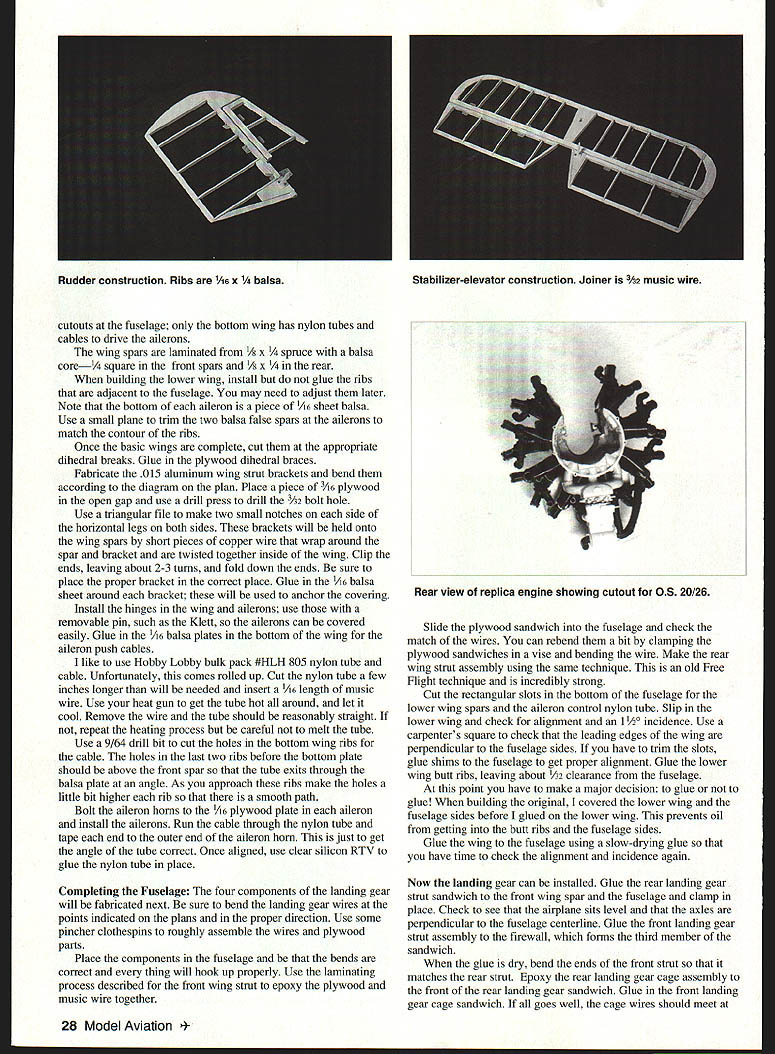
Empennage
- Build the rudder and elevator flat over the plans. All ribs are 1/16" x 1/4" and require a 1/16" x 1/4" slot in the center at the end of each rib to accept the trailing edge. Sand the airfoil shapes afterward.
- Join the elevator halves with a 3/32" piece of music wire.
- The leading edge of the vertical fin fits into a hole in the 1/4" balsa sheet at the center of the stabilizer. Once the stabilizer is glued to the fuselage, scallop the formers between the upper fuselage stringers with a round file or router so that when the upper fuselage is covered only the stringers touch the covering.
Replica Engine
- A plastic kit of the Wright J-5 Whirlwind engine can be used as the basis for an engine replica (or you can build up cylinders from Williams Bros. 1/2"-scale J5 cylinders).
- After assembly (omit the top cylinder), cut away the back of the crankcase to match the engine mounts. Cut a hole in the front of the crankcase to allow the prop shaft and driver to pass through. Install the O.S. 20/26 engine and confirm the plastic engine will slip over the model engine with sufficient prop clearance and that the back of the plastic engine will sit against the engine mounts or balsa blocks.
- Cover the O.S.'s crankcase with clear kitchen wrap. Mix about three ounces of auto-body filler and fill the sides and bottom of the plastic engine. Slip the plastic engine over the model engine, align it, and hold until the filler hardens. Remove the plastic engine and trim excess filler. Small wood screws can hold the replica engine in place.
Covering and Finish
- Use iron-on heat-shrink film for covering. The wings and empennage are bright yellow and the fuselage is olive drab.
- Paint the balsa blocks forward of the firewall with olive-drab dope. Apply national insignia to the top of the upper wing and the bottom of the lower wing from trim film. Large white numbers and the red, white, and blue strips on the rudder are trim film. Small white words and numbers on the fuselage sides were 3/8" press-on vinyl letters.
- The pilots are Williams Bros. 1-1/2" scale sportsman figures painted with plastic model paints. Paint helmets and jackets dark brown.
- I originally used Williams Bros. 3-5/8" Golden Age wheels but later replaced them with three-inch wire-spoke wheels for their appearance.
Flying
- Scale biplanes of this size pair well with the O.S. 20/26 four-stroke; the sound is evocative of a radial engine. Set the needle valve so the engine runs smoothly without over-revving.
- The best propeller found for this combination is a Master Airscrew 9x6. Reset the exhaust pipe to point upward at about 45° to aim oil away from the fuselage and keep the model clean.
- Control throws (recommended):
- Ailerons: 1/2" up, 3/8" down
- Elevator: 1/2" up, 3/8" down
- Rudder: 1" right, 1" left
- Takeoff is straightforward, with little or no rudder input. Once airborne, reduce throttle until the model looks like it is just loafing along. The PT-3 will perform large, lazy loops, open slow rolls, wingovers, and spins.
- The four-stroke engine will throttle down so the prop is just ticking over, making it fun to fly slow patterns and perform touch-and-go landings. Rigid landing gear on models of this type tends to make landings easier and smoother.
Frank Baker 5301 Burnett Dr. Madison, WI 53705
Transcribed from original scans by AI. Minor OCR errors may remain.

