
Pulse Mini-Lab
Bob Kopski
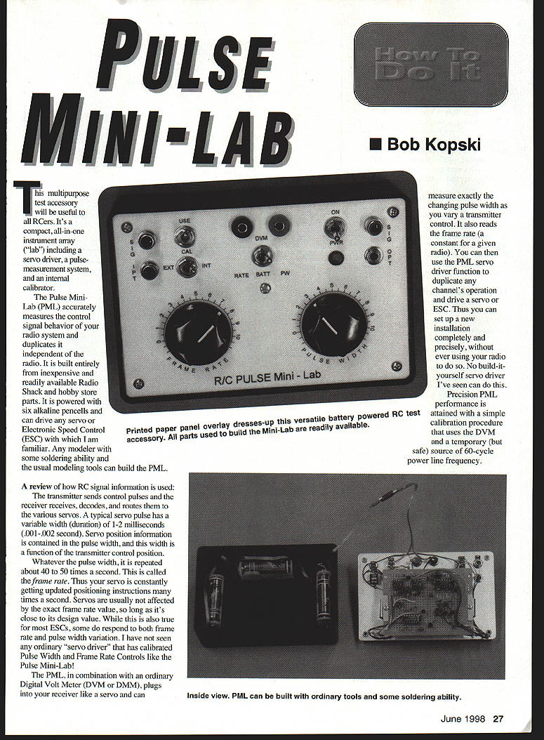
This multipurpose test accessory will be useful to all RCers. It's a compact, all-in-one instrument array ("lab") including a servo driver, a pulse-measurement system, and an internal calibrator.
The Pulse Mini-Lab (PML) accurately measures the control-signal behavior of your radio system and duplicates it independent of the radio. It is built entirely from inexpensive and readily available Radio Shack and hobby-store parts. It is powered with six alkaline pen cells and can drive any servo or Electronic Speed Control (ESC) with which I am familiar. Any modeler with some soldering ability and the usual modeling tools can build the PML.
A review of how RC signal information is used:
- The transmitter sends control pulses; the receiver receives, decodes, and routes them to the various servos.
- A typical servo pulse has a variable width (duration) of about 1–2 milliseconds (0.001–0.002 second). Servo position information is contained in the pulse width, and this width is a function of the transmitter control position.
- Whatever the pulse width, it is repeated about 40–50 times per second (the frame rate). Servos are usually not affected by the exact frame rate value, so long as it's close to its design value. Some ESCs, however, do respond to both frame-rate and pulse-width variation.
The PML, used with an ordinary Digital Volt Meter (DVM or DMM), plugs into your receiver like a servo and can measure the changing pulse width as you vary a transmitter control. It also reads the frame rate (which is essentially constant for a given radio). You can then use the PML servo-driver function to duplicate any channel's operation and drive a servo or ESC. Thus you can set up a new installation completely and precisely without using your radio.
Precision PML performance is attained with a simple calibration procedure that uses the DVM and a temporary (but safe) source of 60 Hz power-line pickup.
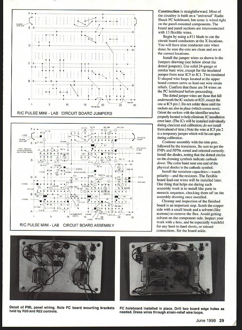
Overview of the circuit and operation
- The basic servo driver consists of a Frame Rate Generator (FRG) and a Pulse Width Generator (PWG). The FRG produces the 40–50 Hz frame rate. The PWG makes the variable-width control pulse. Both generators have control knobs on the PML panel.
- Frame Rate Voltage and Pulse Width Voltage converter circuits individually convert frequency and duration information to DC voltages. Once calibrated, the voltages permit precise display of frame rate and pulse width on an ordinary DVM. Both parameters can be measured for externally supplied signals or internal servo-driver signals.
- The PML operates from an internal six-pen-cell battery and includes a 5 V regulator to power the internal circuitry and the servo or ESC under test.
- Several panel-mounted switches select PML functions by interconnecting input and output signals among internal functional blocks.
Detailed circuit description (summary)
- The servo driver uses a 4069 hex inverter (IC3). Sections c and d form a hysteresis latch; section e is connected as a linear operational integrator (a classic function-generator arrangement). Frame Rate control R20 varies the integration constant; lower resistance raises the function-generator frequency. R20 is designed to vary frame rate over a nominal 30–60 Hz range.
- The latch produces a crisp square wave at IC3d pin 4; the differentiated network (C11, R21, D4) produces negative-going spikes that trigger TLC555 monostable timers IC4 and IC5.
- Timer IC4 is the Pulse Width Generator; it produces the output pulse at the frame rate. Output pulse width is adjustable from about 0.75 to about 2.5 ms via control R22. The combination of FRG and PWG delivers a control pulse that behaves like a receiver output.
- Timer IC5 also produces a frame-rate pulse and serves two purposes:
- For the Frame Rate to Voltage (FR/V) converter: IC5's output is filtered (R30/C17) and buffered by IC1d, resulting in a DC average voltage read by the DVM. The measurement ratio is set during calibration (one volt per 100 Hz nominally).
- IC5 supplies a precision calibration pulse (via Q5) for calibrating the Pulse Width to Voltage (PW/V) converter.
- The PW/V converter (C1 through R11) monitors pulses at the output connector (internal or external). These pulses turn Q1 on and Q2 off for the pulse duration. With Q2 off, an electronic current pump (IC1a, Q3, etc.) linearly charges capacitor C2 at a rate set by trimmer R6. The ramp on C2 is coupled to a peak-hold circuit (IC1b, Q4, etc.), and the peak is held on capacitor C3. IC1e buffers this voltage and drives the external DVM.
- The ramp voltage at the end of the pulse is directly proportional to the pulse width. Once calibrated, the DVM displays pulse duration with a basic relationship of 1 volt per ms. Pulse widths from about 0.5 to more than 2.5 ms (5 to 25 volts as ramp output pre-buffer) can be read with about 1% accuracy.
External-input mode
- With SW3 in the EXT position, the internal function generator is disabled and PML accepts external input pulses (from a receiver, another servo driver, or a 60 Hz calibrator).
- External inputs route to the output connector, the PW/V converter, and the bandpass amplifier block (IC3a/IC3b). The amplifier drives the hysteresis latch and triggers IC4/IC5 as described. IC5 is used to measure the rate of incoming signals and to calibrate the PW/V converter with a 60 Hz external signal.
Construction (overview)
- Most of the circuitry is built on a Radio Shack universal PC holeboard; some wiring is done directly on panel-mounted components. The board and panel are interconnected with flexible wires (13 main connections between board and panel).
- Begin by cutting the circuit board conductors at the X locations on the board drawing. There will be nine conductor cuts; ensure they are clean and correctly located.
- Install jumper wires as shown in the jumpers drawing (see notes about dotted jumpers below). Use solid 24-gauge or similar bare wire, except for the insulated jumper from near IC5 to IC1. Two insulated U-shaped wire loops at the upper board corners serve as lead-out wire strain reliefs. Confirm there are 54 wires on the PC holeboard before proceeding.
- Dotted jumper wires fall underneath IC sockets or R25, except the one at IC5 pin 2. Do not solder these until the sockets are in place. Orient sockets correctly to avoid IC installation errors. The wire at IC5 pin 2 is a temporary jumper that will be cut during calibration.
- Continue assembly with trim pots, then transistors (check PNP vs NPN orientation). Install diodes (observe polarity—the color band marks the cathode). Install tantalum capacitors and resistors. Install flexible board lead-out wires later.
- Clean the copper side with a small brush and solvent (e.g., acetone) to remove flux; avoid getting solvent on the component side. Inspect the board with a lens for shorts or missed connections.
- Panel assembly: mark, drill, deburr holes, and install panel-mounted components. A printed paper overlay can be applied before installing parts. PC board mounting brackets are held between controls R20 and R22 and the panel. Regulator IC2 is mounted to the panel (its metal mounting surface and the panel are electrical ground). Bend and cut IC2 leads to serve as wiring points. Observe polarity for C4, C5 and LED D1.
- Use colored R/C wire for panel wiring and board-to-panel wiring. Solder wires to the board first, dress them as needed, then cut to final length to reach panel components. The board and panel should be able to lay flat with about 1½" separation for final wiring.
- Battery holders: three two-cell holders are attached to the case walls with hook-and-loop (Velcro). Solder wires directly to the battery case terminals—do not use nine-volt snaps. Wire the holders in series to produce nominal 9 V from six pen cells. Consider using two pins of a three-pin Deans connector between the battery and the electronics to allow convenient disconnection. Check for mechanical interference before final assembly.
PML Checkout / Calibration Please follow this sequence and do not proceed to the next step until the current one is working as described. During the steps below you will connect a DVM to various internal test points. Connect the DVM negative lead to the bare wire loop marked "test clip loop" on the board assembly drawing (near location 20). Use small test clips and take care not to short adjacent pins. Use the DVM DC range of 20 V (or 30 V). In actual use the DVM will only be connected to the two banana jacks on the PML panel.
- Initial power checks
- Set switches:
- SW1 = OFF
- SW2 = USE
- SW3 = EXT
- SW4 = mid-position (BATT)
- Set all controls and trim pots to mid-range.
- Install the battery but do not connect signal inputs or outputs.
- Temporarily connect the DVM (+) lead to the (+) DVM banana jack.
- Turn on SW1; LED D1 should light. The DVM should read approximately 9 V (or slightly more).
- Switch SW4 to RATE, then to PW; the DVM reading should drop to about 0.1 V and 0.2 V respectively. Leave SW4 on PW.
- Connect the (+) meter lead to regulator IC2 output pin (where C4 is connected) and check for 5.0 ± 0.1 V. Note this exact regulator voltage and turn SW1 off.
- IC3 check and 60 Hz pickup test
- Install IC3 only (ensure correct orientation). Turn SW1 on.
- Measure IC3 pin 12 and pin 8 voltages; both should be about 2.5 ± 0.3 V.
- Measure IC3 pin 4; it will normally be around 0 V or 5 V, and pin 6 will be the opposite. With SW3 on INT, pin 4 should read around 2.5 V and may jitter.
- Switch SW3 to EXT.
- Connect a length of wire to the input jack and hold this wire in your hand while near a line-operated appliance (lamp, radio, toaster) so the wire acts as a 60 Hz pickup/antenna. Proper operation is indicated by a DVM reading of about 2.5 ± 0.3 V on IC3 pin 4. If it remains at 0 or 5 V, there is either insufficient 60 Hz pickup or wiring is incorrect. Otherwise, remove the antenna and turn off SW1.
- IC5 calibration (Frame Rate to Voltage)
- Install IC5 and turn on SW1.
- Measure voltage on IC5 pin 3; it should equal the regulator voltage noted earlier.
- Cut the temporary jumper from IC5 pin 2 to ground; IC5 pin 3 should drop to zero.
- Reactivate the 60 Hz antenna; IC5 pin 3 voltage should rise to several hundred millivolts.
- Adjust R26 for IC5 pin 3 to read 0.60 V. This calibrates the FR/V converter. Later, with IC1 installed, the same reading will be verified at the DVM terminals.
- Remove the antenna and switch off SW1.
- Set Frame Rate control range (R19)
- This step sets the Frame Rate control knob range and involves adjusting R19 (made in two parts a and b).
- Turn SW1 on, set SW3 to INT, vary R20 over its range, and note IC5 pin 3 DVM readings. The goal is to have the range cover about 30–60 Hz (0.30–0.60 V).
- If the range does not cover this, adjust R19 (increase R19 to shift downward, decrease to shift upward). Replace R19a or R19b with the nearest resistor value step-by-step until a suitable range is obtained (aim to cover ~0.40–0.50 V with some margin).
- Final range need not be perfect; just ensure it more-than-covers normal transmitter limits. Turn SW1 off when done.
- IC4 pulse-width-endpoint trim
- Install IC4 and connect the DVM positive lead to IC4 pin 3.
- With SW1 on, SW3 on EXT, and the 60 Hz antenna operational, vary the Output Pulse Width knob limit-to-limit and note the two DVM readings.
- Adjust R25 to obtain knob-limit values of about 0.24 V and 0.74 V. This will be verified later at the DVM panel jacks. Turn SW1 off.
- Install IC1 and calibrate PW/V
- Install IC1, set SW2 to CAL, SW3 to EXT, SW4 to RATE, reconnect the 60 Hz pickup, and turn on SW1.
- Verify a meter reading of 0.60 V at IC5 pin 3 and at the DVM positive panel jack. Switch SW4 to PW; the DVM should read between 1.5 and 2.5 V.
- Using the previously noted IC2 regulator voltage (Vreg), adjust R6 for a DVM reading given by V = 10 / (Vreg). Example: if IC2 reads 4.96 V, adjust R6 for V = 10 / 4.96 ≈ 2.016 V; choose 2.02 V on the meter. This calibrates the PW/V circuit.
- Final PW range verification
- With the DVM connected to the panel-mounted jacks, set SW1 on, SW2 to USE, SW3 to INT, SW4 to PW.
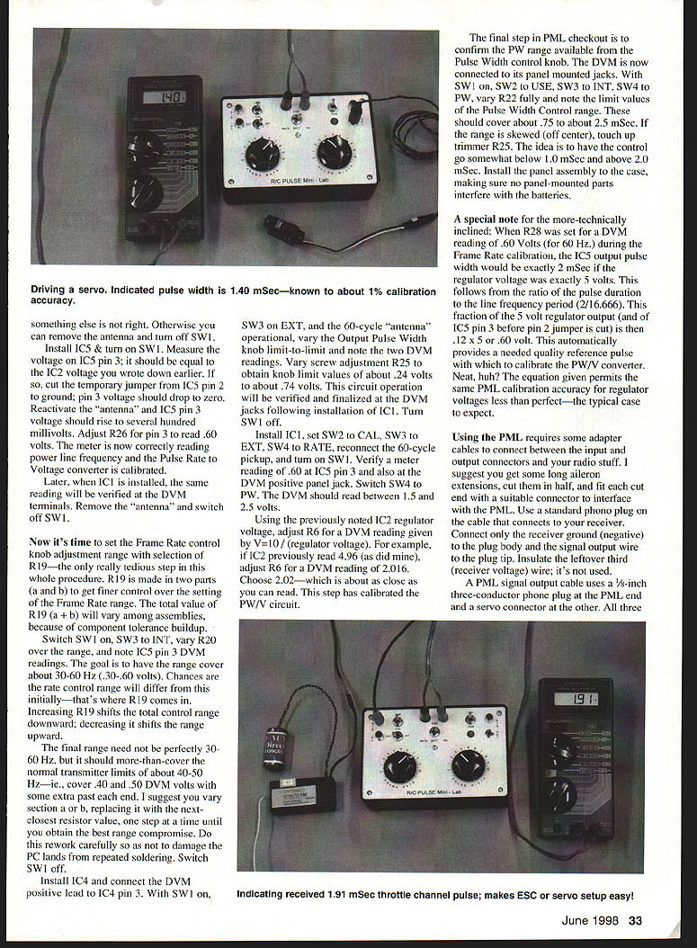
- Vary R22 fully and note pulse-width control limits; they should cover about 0.75 to about 2.5 ms.
- If off-center, adjust trimmer R25. Aim for a control range that goes somewhat below 1.0 ms and above 2.0 ms.
- Install the panel assembly to the case, ensuring no panel-mounted parts interfere with the batteries.
Calibration note for the technically inclined:
- When R28 is set so that the DVM reads 0.60 V (for 60 Hz) during Frame Rate calibration, the IC5 output pulse width will be exactly 2 ms if the regulator voltage is exactly 5 V. The ratio arises from pulse duration to line-frequency period and the fraction of the 5 V regulator output. The equation used allows accurate PW/V calibration even when regulator voltage is not exactly 5 V.
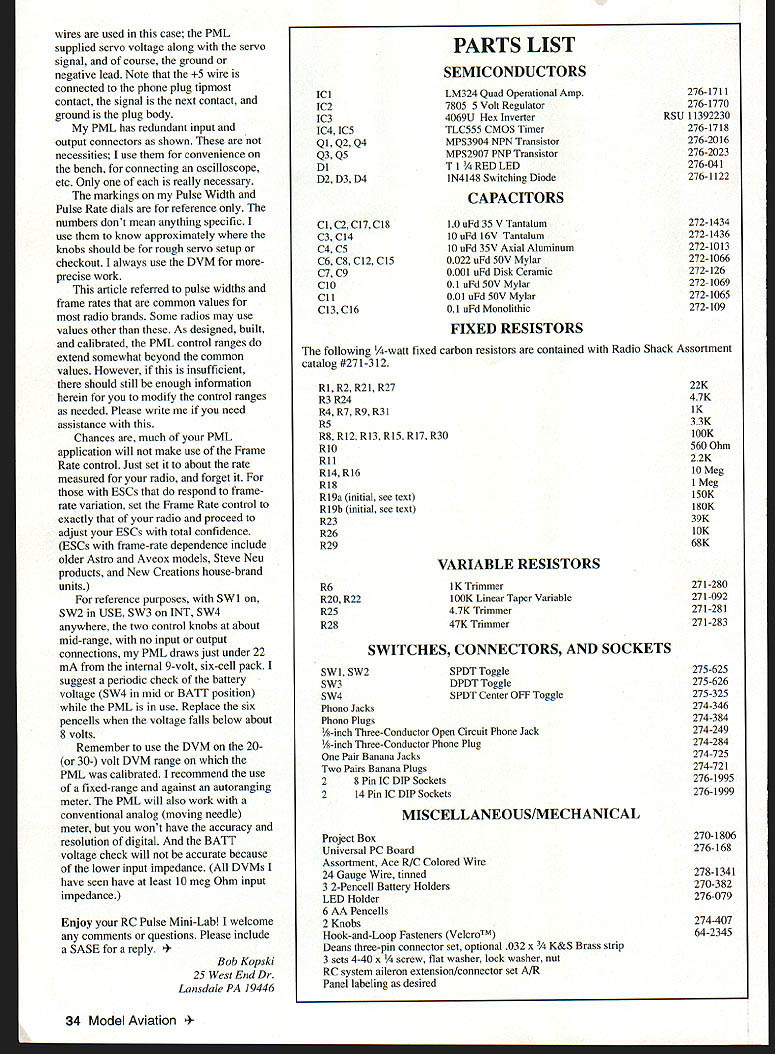
Cables and connections
- You will need adapter cables to connect the PML to your radio equipment. Suggested method:
- Get long servo extensions, cut them in half, and fit each cut end with a suitable connector for the PML.
- Use a standard phono plug on the cable that connects to your receiver: connect only receiver ground (negative) to the plug body and the signal wire to the plug tip. Insulate the unused receiver-voltage wire.
- A PML signal output cable uses a 1/8-inch three-conductor phone plug at the PML end and a servo connector at the other. All three conductors are available to test both standard and JR/Futaba wiring. If you buy a ready-made cable, look for a stereo plug and a 3-pin servo connector. Making your own is cheaper and convenient.
Note on phone-plug wiring:
- Three wires are used: +5 V, signal, and ground. The PML supplies servo voltage (+5), the servo signal, and ground.
- Mapping on the 1/8" phone plug: +5 wire to the tipmost contact, signal to the next contact, and ground to the plug body.
Miscellaneous notes
- My PML has redundant input and output connectors for convenience (scope, bench use). Only one of each is necessary.
- The markings on the Pulse Width and Pulse Rate dials are for reference only. I use a DVM for precise work.
- Some radios may use pulse widths or frame rates outside the common values; the PML control ranges extend somewhat beyond common values. If insufficient, the circuit can be modified—contact me for assistance.
- Most PML applications will not require frequent frame-rate adjustment—set it to your radio's measured rate and leave it.
- Certain ESCs (older Astro, Aveox models, Steve Neu products, New Creations house-brand units) do respond to frame-rate changes; for those, match the PML frame rate to your radio when setting up ESCs.
- With SW1 on, SW2 in USE, SW3 on INT, SW4 anywhere, knobs at mid-range, and no I/O connections, my PML draws just under 22 mA from the internal 9 V pack. Periodically check battery voltage (SW4 in mid or BATT position) and replace the six pen cells when voltage falls below about 8 V.
- Use the same DVM range used for calibration (20 V or 30 V). Fixed-range meters are recommended over autoranging. Analog meters can work but lack the accuracy and resolution of a digital meter; analog input impedance can also affect battery checks.
Enjoy your RC Pulse Mini-Lab! I welcome comments or questions. Please include a SASE for a reply.
Bob Kopski 25 West End Dr. Lansdale, PA 19446
Parts List
Semiconductors
- IC1: LM324 Quad Operational Amp
- IC2: 7805 5 Volt Regulator
- IC3: 4069 Hex Inverter
- IC4, IC5: TLC555 CMOS Timer
- Q1, Q2, Q4: MPS3904 NPN Transistor
- Q3, Q5: MPS2907 PNP Transistor
- D1: T1 3/4 RED LED
- D2, D3, D4: 1N4148 Switching Diode
Capacitors
- C1, C2, C17, C18: 1.0 µF 35 V Tantalum
- C3, C14: 10 µF 16 V Tantalum
- C4, C5: 10 µF 35 V Axial Aluminum
- C6, C8, C12, C15: 0.022 µF 50 V Mylar
- C7, C9: 0.001 µF Disk Ceramic
- C10: 0.1 µF 50 V Mylar
- C11: 0.01 µF 50 V Mylar
- C13, C16: 1.0 µF Monolithic
Fixed Resistors (1/4-watt carbon unless noted)
- R1, R2, R21, R27: 22K
- R3, R24: 4.7K
- R4, R7, R9, R31: 1K
- R5: 3.3K
- R8, R12, R13, R15, R17, R30: 100K
- R10: 560 Ω
- R11: 2.2K
- R14, R16: 10 MΩ
- R18: 1 MΩ
- R19a (initial, see text): 150K
- R19b (initial, see text): 180K
- R23: 39K
- R26: 10K
- R29: 68K
Variable Resistors
- R6: 1K Trimmer
- R20, R22: 100K Linear Taper Variable
- R25: 4.7K Trimmer
- R28: 47K Trimmer
Switches, Connectors, and Sockets
- SW1, SW2: SPDT Toggle
- SW3: DPDT Toggle
- SW4: SPDT Center-OFF Toggle
- Phono jacks and plugs
- 1/8-inch three-conductor open-circuit phone jack
- 1/8-inch three-conductor phone plug
- One pair banana jacks
- Two pairs banana plugs
- 2 × 8-pin IC DIP sockets
- 2 × 14-pin IC DIP sockets
Miscellaneous / Mechanical
- Project box
- Universal PC board
- Assortment Ace R/C colored wire
- 24-gauge tinned wire
- 3 × 2-pen-cell battery holders
- LED holder
- 6 AA pen cells
- 2 knobs
- Hook-and-loop fasteners (Velcro™)
- Deans three-pin connector set (optional)
- .032 x 3/4 K&S brass strip (optional)
- 3 sets 4-40 × 1/4 screw, flat washer, lock washer, nut
- RC system aileron extension/connector set (as required)
- Panel labeling as desired
Transcribed from original scans by AI. Minor OCR errors may remain.

