
Quick and Clean Canopy Attachment System - 2008/09
Introduction
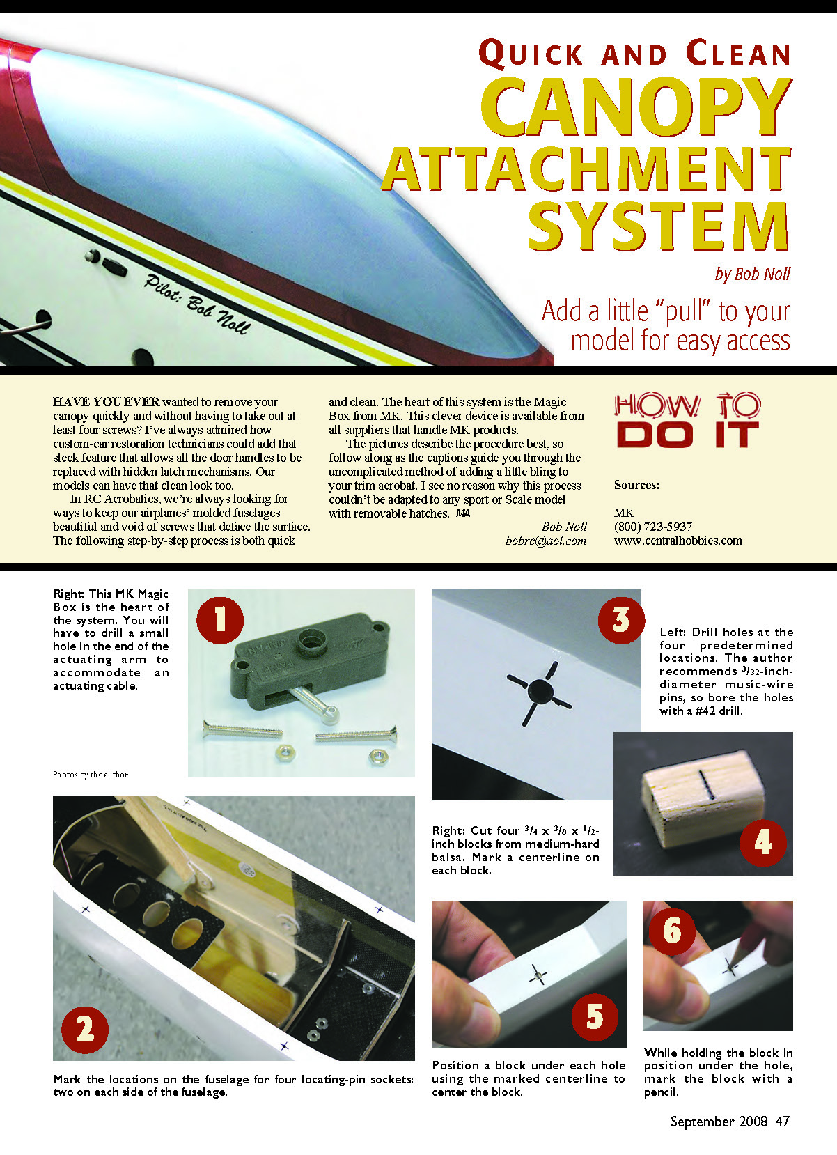
Have you ever wanted to remove your canopy quickly without having to remove four or more screws? In RC aerobatics we try to keep molded fuselages beautiful and free of screws that mar the surface. The following step-by-step system is quick and clean. The heart of this system is the MK Magic Box, available from suppliers that handle MK products. The pictured captions in the original article describe the procedure; the text below follows that uncomplicated method and can be adapted to sport or scale models with removable hatches.
Author
- Bob Noll
- [email protected]
Materials
- MK Magic Box
- Brass tubing (7/32" diameter) sharpened with a #11 blade (to make a hole cutter)
- Drafting template and drill press
- Blocks (for drilling and mounting)
- Medium fuel tubing, cut into 1/2" pieces
- 1/16" plywood (to retain fuel tubing)
- Music wire, cut into 5/8" lengths
- Pins and small mounting blocks
- Canopy and fuselage
- Leather punch
- Small square pieces of waxed paper (shields)
- Masking tape (small pieces as dams)
- Epoxy and microballoons
- 1/8" diameter aluminum tubing
- Hard balsa blocks (drilled to accept tubing)
- Coated cable (for pull cord)
- Two pieces of 1/8" x 1/2" medium-hard balsa (for crossmember)
- 1/4" clearance drill and two 3/32" mounting holes drill
- 1/4-square medium-hard balsa (for canopy pin support)
- 1/8" plywood or phenolic tabs
- 1/8" light plywood backers (front and rear)
- Fiberglass and/or microballoon mixtures for reinforcement
- Loop and ferrule for pull cord finish
Procedure
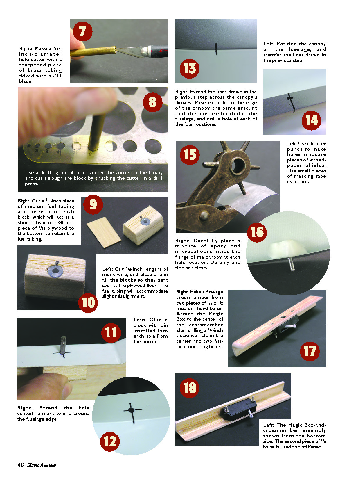
- Make a 7/32" diameter hole cutter from a sharpened piece of brass tubing (skived with a #11 blade). Use a drafting template to center the cutter on the block and cut through the block by chucking the cutter in a drill press.
- Cut 1/2" pieces of medium fuel tubing and insert one into each drilled block; these will act as shock absorbers. Glue a piece of 1/16" plywood to the bottom of each block to retain the fuel tubing.
- Cut 5/8" lengths of music wire and place one in each block so the wire seats against the plywood floor. The fuel tubing will accommodate slight misalignment.
- Glue each block (with pin installed) into its hole from the bottom.
- Extend the hole centerline mark to and around the fuselage edge.
- Position the canopy on the fuselage and transfer the centerline/edge lines you just drew.
- Extend the transferred lines across the canopy flanges. Measure in from the edge of the canopy the same distance the pins are set into the fuselage and drill a hole at each of the four locations.
- Use a leather punch to make holes in small square pieces of waxed paper shields. Use small pieces of masking tape as dams where needed.
- Carefully place a mixture of epoxy and microballoons inside the canopy flange at each hole location. Do only one side at a time to maintain alignment and cleanliness.
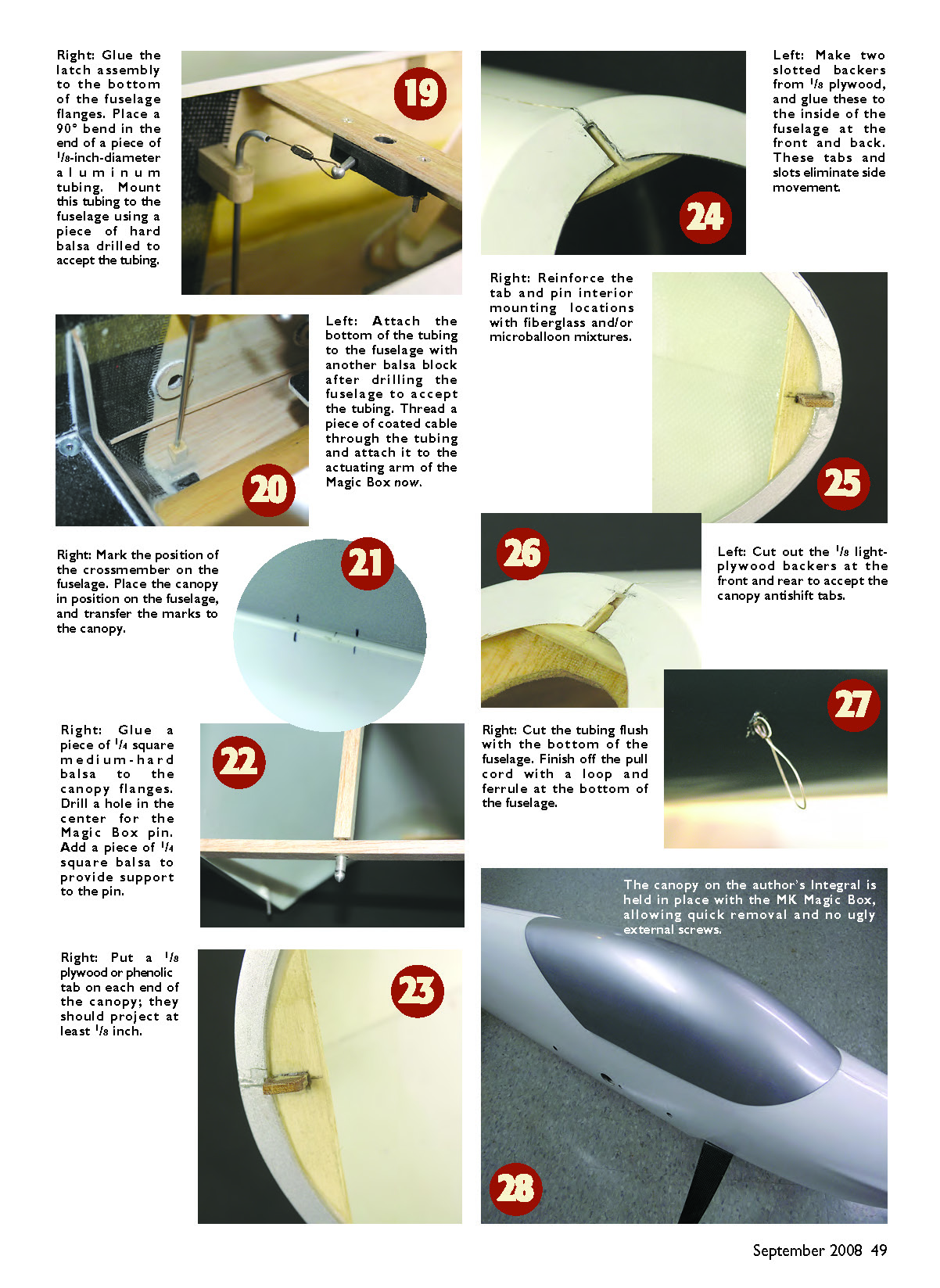
- Glue the latch assembly to the bottom of the fuselage flanges. Form a 90° bend in the end of a piece of 1/8" diameter aluminum tubing and mount this tubing to the fuselage using a hard balsa block drilled to accept the tubing.
- After drilling the fuselage to accept the tubing, attach the bottom of the tubing to the fuselage with another balsa block. Thread a piece of coated cable through the tubing and attach it to the actuating arm of the Magic Box.
- Mark the position of the crossmember on the fuselage. Place the canopy in position and transfer the crossmember marks to the canopy.
- Make a fuselage crossmember from two pieces of 1/8" x 1/2" medium-hard balsa. Drill a 1/4" clearance hole in the center and two 3/32" mounting holes, then attach the Magic Box to the center of the crossmember. Use the second 1/8" balsa piece as a stiffener.
- Glue a piece of 1/4-square medium-hard balsa to the canopy flanges. Drill a center hole in this balsa for the Magic Box pin. Add another piece of 1/4-square balsa to provide additional support for the pin.
- Put a 1/8" plywood or phenolic tab on each end of the canopy; the tabs should project at least 1/8".
- Make two slotted backers from 1/8" plywood and glue these to the inside of the fuselage at the front and rear. These tabs and slots eliminate side movement of the canopy.
- Reinforce the tab and pin interior mounting locations with fiberglass cloth and/or microballoon mixtures for added strength.
- Cut out the 1/8" light-plywood backers at the front and rear to accept the canopy anti-shift tabs.
- Cut the aluminum tubing flush with the bottom of the fuselage. Finish the pull cord with a loop and ferrule at the bottom of the fuselage for neat, accessible operation.
Notes
- Work one side at a time when glassing or epoxy-setting canopy flange areas to maintain precise alignment.
- The fuel-tubing shock absorbers allow for small misalignments between pins and holes.
- The Magic Box-and-crossmember arrangement centralizes the latch mechanism, and the 1/4-square balsa supports the pin to prevent flange tearing.
The canopy on the author's Integral is held in place with the MK Magic Box, allowing quick removal and eliminating unsightly external screws.
Sources
- MK
- Phone: (800) 723-5937
- www.centralhobbies.com
Transcribed from original scans by AI. Minor OCR errors may remain.

