
RADIO CONTROL SCALE AEROBATICS
Mike Hurley 11542 Decatur Ct., Westminster CO 80234 E-mail: [email protected]
Introduction
When JR first introduced its digital servos, I was one of the first in line to take advantage of the new technology. Digital servos offer increased position-holding ability and precision that is unmatched by an analog servo. At the time of their introduction I was flying large aerobatic aircraft, and the need for a stronger, more precise servo was evident. But when I installed the servos ganged together to operate a single control surface, it became clear that there was a downside to precision position-holding with a very low tolerance.
The problem with ganged digital servos
All servos have manufacturing differences in centering position, endpoints, and total overall travel. When a servo that has low positioning tolerance is coupled to another servo with low tolerance but differing points of reference, problems can occur. Analog servos tolerate being forced to work together when not exactly synchronized; digital servos, however, output full power to retain their precise position and only work together when endpoints and centering are exactly matched.
Early attempts to match servos
When I first ran into this problem, I devised a measuring device that could be used to match individual servos to find ones that could be used together on a single surface (see the September 2001 Scale Aerobatics column). Although measuring and matching works in many cases, it is a limited solution at best. One answer would be servos that were individually programmable through your transmitter, a computer, or a handheld device. Programmable servo technology is available from other manufacturers, but JR chose a different approach.
I spoke with JR Research and Development about why they have chosen not to build programmable servos. JR tested the IC chips that would allow programmability and felt the compromise in quality, precision, and reliability would be too great given currently available parts. R&D concluded they could not create a programmable servo that met JR’s specifications. Instead, JR developed an external device placed in line from the receiver to the servo called the MatchBox.
JR’s MatchBox solution
Initially I was skeptical. At first glance it seemed like more equipment and more electronics to add to the mix. But for people who already have a significant investment in JR digital servos, the MatchBox is a much better, cost-effective upgrade that improves the manageability and flexibility of any JR servo.
Key points about the MatchBox:
- Works with any JR servo, analog or digital.
- Allows real-time adjustments in the airplane rather than setting points on a test jig.
- Helps compensate for slight imperfections in airplane construction.
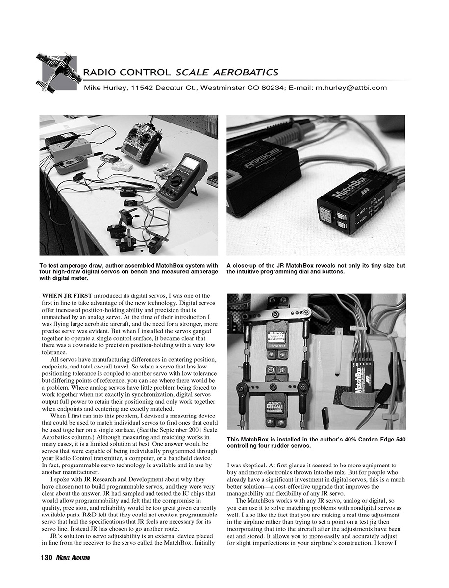
The MatchBox is a surprisingly tiny device weighing just 0.32 ounce. It is designed to operate from one receiver channel and can control up to four servos separately.
MatchBox features and programming
Programming the MatchBox is quick and easy once installed. Controls include a dial and increase/decrease buttons:
- The dial has eight positions. For example, positions 1–4 select the four servos; positions 5–8 select the same servos while reversing their direction.
- The radio stick position dictates whether you’re adjusting endpoints or centering.
- To store a setting, rotate the dial past 9 and back to 0 before powering off.
- Once programmed and the dial is in the 0 position, no further adjustments can be made, so vibration cannot affect the settings.
Because the unit can operate four servos from one channel, it includes a provision for an external battery that isolates and supplies power only to the servos attached to the MatchBox. Many pilots use the MatchBox powered only from the receiver; to use receiver power, the supplied jumper must be installed in the auxiliary power channel of the MatchBox.
Power and testing
I wanted to determine whether powering four servos through one receiver channel caused issues, so I conducted a few practical tests. JR states that a fully stalled DS8411 draws 1.6 amps; four of them together would attempt to pull 6.4 amps through one receiver channel. The MatchBox itself uses about 12 mA.
My testing equipment could not capture millisecond-level peak draws, but I performed simple load tests:
- Measured approximately 800 mA draw from a single servo under heavy load (my test setup).
- Measured roughly 3.3 amps with all four servos stalled together.
- Idle draw was approximately 130 mA when servos were powered through the receiver with the MatchBox jumpered.
- When powered directly through the MatchBox (external power), idle draw dropped to about 80 mA because the receiver was not being powered.
- Tests with Ni-Cd and NiMH batteries yielded essentially identical results and never exceeded what the receiver bus or battery packs could handle.
I could not find an instance where the power supply faltered through a single channel, whether the MatchBox was powered externally or through the receiver. JR reports units in aircraft across the country performing as expected without external power.
Recommendations:
- Avoid exceeding 10 servos on one receiver through multiple MatchBoxes.
- When more than 10 servos are needed, use the MatchBox external battery port, an isolated power bus, or split the load between two receivers.
Suggested installations and plans
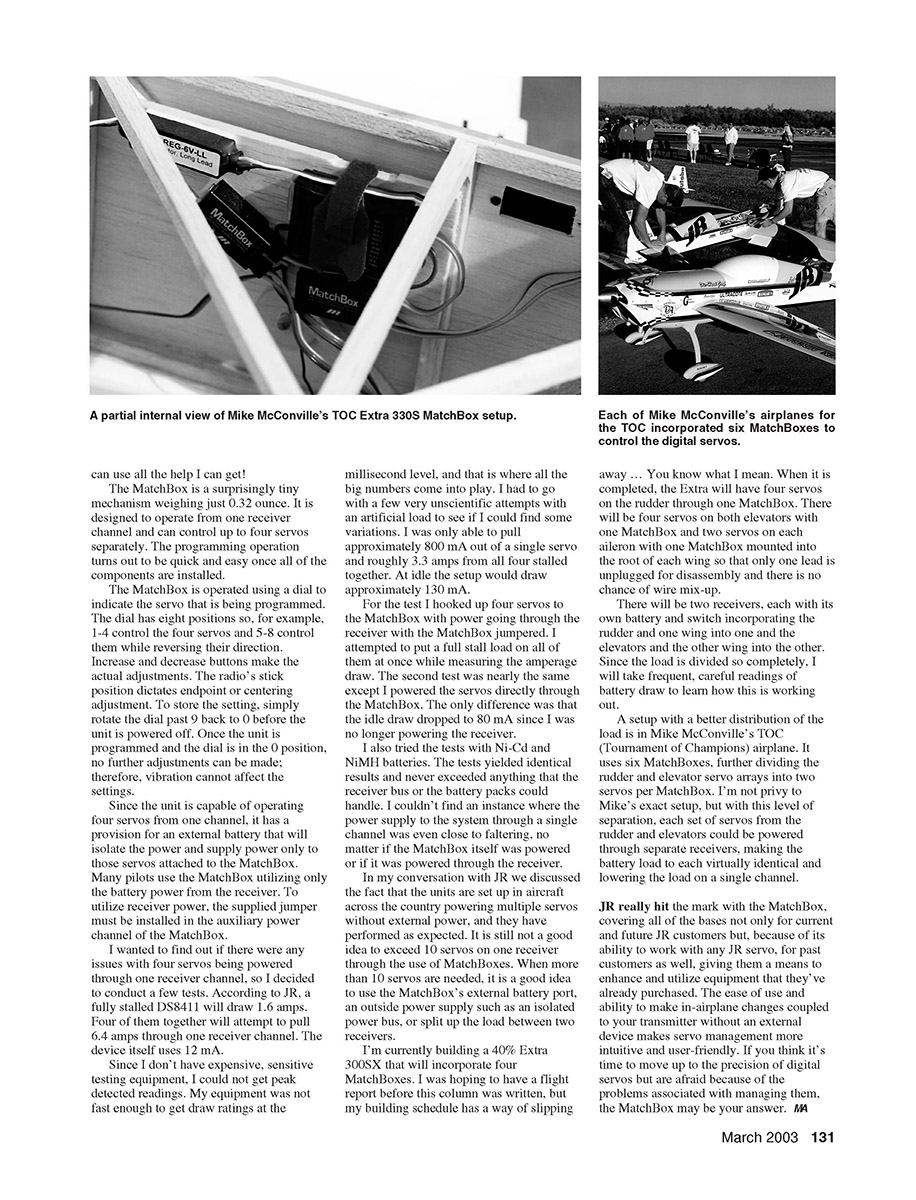
I’m building a 40% Extra 300SX that will incorporate four MatchBoxes. Planned layout:
- Four servos on the rudder controlled by one MatchBox.
- Four servos on each elevator controlled by one MatchBox.
- Two servos on each aileron with one MatchBox mounted in the root of each wing so only one lead is unplugged for disassembly (reduces chance of wire mix-up).
- Two receivers, each with its own battery and switch: one receiver will handle the rudder and one wing; the other will handle the elevators and the other wing.
I will take frequent, careful readings of battery draw to evaluate performance.
A different distribution approach is used by Mike McConville in his TOC Tournament of Champions airplane. He has six MatchBoxes, further dividing the rudder and elevator servos and isolating servo groups per MatchBox. With that separation, each group could be powered through separate receivers, making battery load more equal and lowering the load on any single channel.
Conclusion
JR’s MatchBox addresses the common problems of ganged digital servos by providing a flexible, user-friendly means of matching and managing servos in the airplane. It works with existing JR servos (analog or digital), enables in-airplane adjustments via your transmitter, and reduces the need to replace perfectly good hardware. If you want the precision of digital servos but are concerned about managing them when multiple servos drive a single surface, the MatchBox is a practical solution.
Mike Hurley
Transcribed from original scans by AI. Minor OCR errors may remain.

