
RADIO CONTROL AEROBATICS
Eric Henderson 303 Shady Ln., Marlton NJ 08053 E-mail: [email protected]
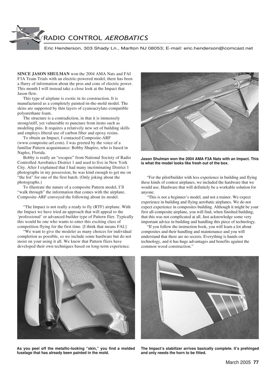
SINCE JASON SHULMAN won the 2004 AMA Nats and FAI F3A Team Trials with an electric-powered model, there has been a flurry of information about the pros and cons of electric power. This month I will instead take a close look at the Impact that Jason flew.
This type of airplane is exotic in its construction. It is manufactured as a completely painted-in-the-mold model. The skins are supported by thin layers of cyanoacrylate-compatible polyurethane foam.
The structure is a contradiction: immensely strong and stiff, yet vulnerable to puncture from items such as modeling pins. It requires a relatively new set of building skills and employs liberal use of carbon fiber and epoxy resins.
To obtain an Impact, I contacted Composite-ARF (www.composite-arf.com). I was greeted by the voice of a familiar Pattern acquaintance: Bobby Shapiro, who is based in Naples, Florida.
Bobby is really an "escapee" from National Society of Radio Controlled Aerobatics District 1 and used to live in New York City. After I explained that I had many incriminating District 1 photographs in my possession, he was kind enough to get me on "the list" for one of the first batch. (Only joking about the photographs.)
To illustrate the nature of a composite Pattern model, I'll walk through the information that comes with the airplane. Composite-ARF conveyed the following about its model:
"The Impact is not really a ready-to-fly (RTF) airplane. With the Impact we have tried an approach that will appeal to the 'professional' or advanced-builder type of Pattern flier. Typically this would be one who wants to enter this exciting class of competition flying for the first time. [I think that means FAI.]
"We want to give the modeler as many choices for individual completion as possible, so we include some hardware but do not insist on your using it all. We know that Pattern fliers have developed their own techniques based on long-term experience.
"For the pilot/builder with less experience in building and flying these kinds of contest airplanes, we included the hardware that we would use. Hardware that will definitely be a workable solution for anyone.
"This is not a beginner's model, and not a trainer. We expect experience in building and flying aerobatic airplanes. We do not expect experience in composites building. Although it might be your first all-composite airplane, you will find, when finished building, that this was not complicated at all. Just acknowledge some very important advice in building and handling this piece of technology.
"If you follow the instruction book, you will learn a lot about composites and their handling and maintenance and you will understand that there are no secrets. Everything is hands-on technology, and it has huge advantages and benefits against the common wood construction."
Construction and materials
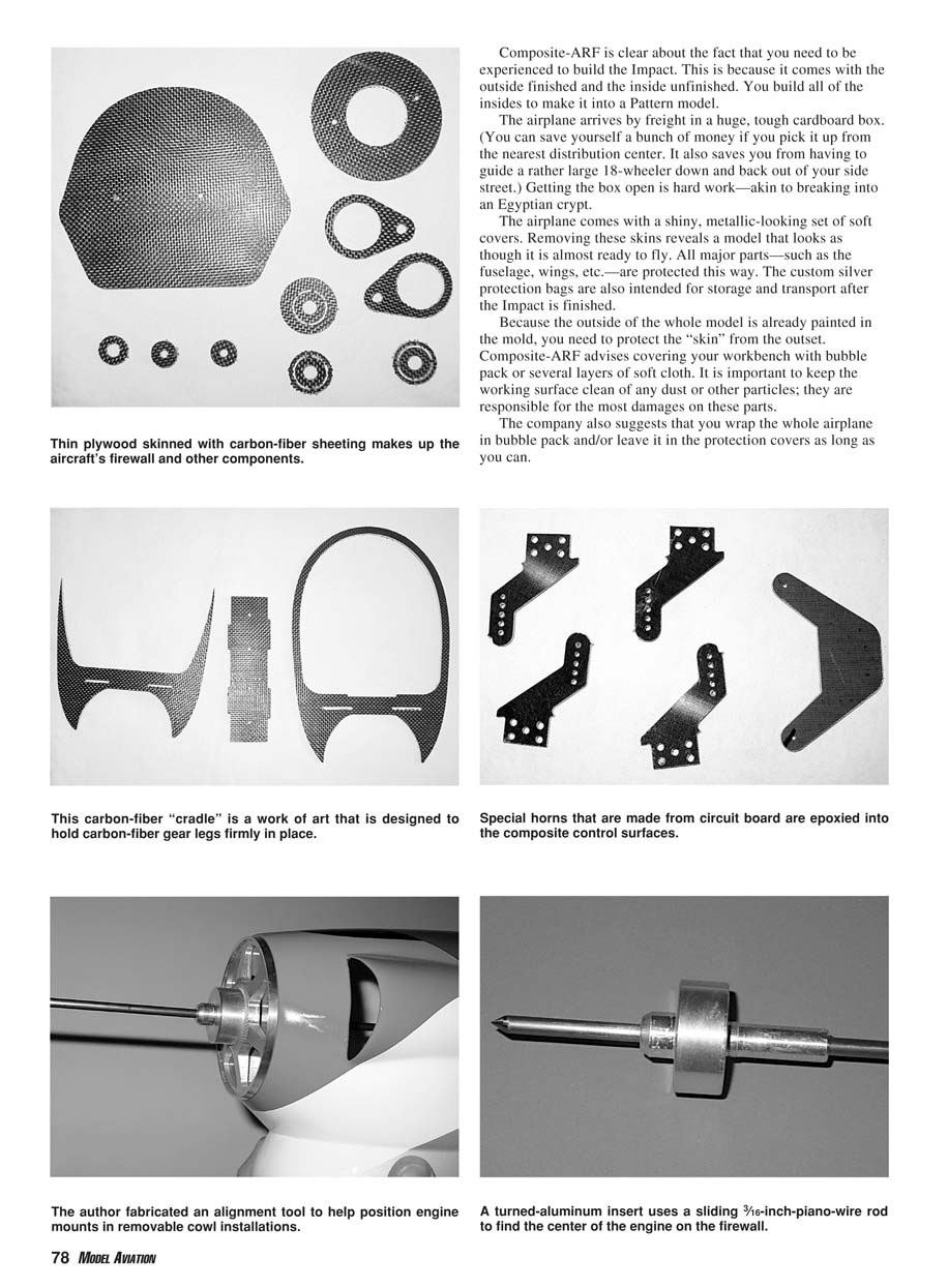
A turned-aluminum insert uses a sliding 3/16-inch piano-wire rod to find the center of the engine on the firewall. Thin plywood skinned with carbon-fiber sheeting makes up the aircraft's firewall and other components. This carbon-fiber cradle is a work of art designed to hold carbon-fiber gear legs firmly in place. Special horns made from circuit board are epoxied into the composite control surfaces. I fabricated an alignment tool to help position engine mounts in removable cowl installations.
Composite-ARF is clear that you need to be experienced to build the Impact. This is because the outside is finished and the inside is unfinished — you build all of the internal structure to make it into a full Pattern model.
Arrival, packaging, and initial handling
The airplane arrives by freight in a huge, tough cardboard box. (You can save yourself a bunch of money if you pick it up from the nearest distribution center. It also saves you from having to guide a rather large 18-wheeler down and back out of your side street.) Getting the box open is hard work—akin to breaking into an Egyptian crypt.
The airplane comes with a shiny, metallic-looking set of soft covers. Removing these skins reveals a model that looks almost ready to fly. All major parts—fuselage, wings, etc.—are protected this way. The custom silver protection bags are also intended for storage and transport after the Impact is finished.
Because the outside of the whole model is already painted in the mold, you need to protect the skin from the outset. Composite-ARF advises covering your workbench with bubble pack or several layers of soft cloth. It is important to keep the working surface clean of dust or other particles; they are responsible for most damages to these parts.
The company also suggests that you wrap the whole airplane in bubble pack and/or leave it in the protection covers as long as you can.
Glues and adhesives
There are many glues that will work with composite aircraft parts and the hardware. Recommended adhesives include thick and thin cyanoacrylate (CA) and 30-minute epoxy. For certain purposes, a thin laminating resin (12- to 24-hour cure type) would be useful.
Use extreme caution with CA. The sandwich of foam will soak up any excess CA, which will then start to cure and generate heat. This heat can be so high that it will deform the outside skin of the fiberglass part.
- Use CA for tacking things in place and epoxy for permanent joints.
- If you want to use CA extensively, use the thick kind; it soaks in more slowly and cures slower.
Landing gear and wing tube installation
The landing-gear support plate is designed to spread the load of the undercarriage through the shell of the fuselage. It consists of a carbon-fiber-and-plywood composite cradle that you glue into the fuselage using an epoxy-resin-and-chopped-fiberglass patch. The result is lightweight and extremely strong.
The wing and stabilizer tubes must be fitted. This is a relatively high-skill task and is crucial to the finished model's performance. The positions of the tubes and adjusters are premarked on the fuselage, but they still need to be fine-tuned for best alignment.
Engine mounting
Composite-ARF recommends a Hyde mount without a nose ring (the "A" type of mount). Fit the firewall and then the Hyde mount to the firewall by trial-fitting the firewall into the fuselage with the correct distance from the nose ring. A good starting position is 2° of side thrust and 0° of downthrust.
After confirming distance and angles, mark the holes showing where to drill to attach the Hyde mount to the firewall. Use a small amount of CA to tack the mount into position. Tack the firewall in position, then permanently glue it in place with resin and chopped fibers.
There are many steps just to mount the engine, and none are easy tasks. Building this airplane is much more like a kit than an ARF in terms of time and effort needed.
Fuselage internals, airflow, and exhaust
The fuselage is completely hollow — an empty shell. This means you must fit a floor to separate the tuned pipe or four-stroke muffler from the fuel tank and the electronics. The floor is supplied with the kit and needs to be fitted and sealed.
Composite-ARF points out that there can be high pressure in the fuselage during flight, which can damage the structure or pop the canopy off, so sealing the airflow from the rest of the fuselage is a requirement not to be ignored.
You also need sufficient cooling air exits in the bottom of the fuselage and at the end of the pipe compartment. Mill out the slots in the side scoops to increase airflow around your engine's crankcase, which provides more engine power and longer life for the crankshaft bearings.
Servos, horns, and hardware
It is unusual, but the company actually recommends specific servo models: JR DS8411 on the ailerons and DS3821 on the elevators (I think the latter would be DS4231 in the U.S.). The cutouts in the stabilizer and wing ribs are made for these servos.
You will have to decide whether to use the supplied hardware. The horns are specially designed to be epoxied into the slots in the control surfaces instead of bolting a horn through the surface. Composite structures do not handle compression well, so gluing the supplied horns is the better option.
Practical tips and wiring
- Make sure fuel lines cannot rub where they pass through carbon-sheeted plywood formers. The edges of carbon components are sharp and can cut fuel tubes in a single flight. Always use bigger holes and appropriate rubber grommets.
- Secure all wiring in the fuselage and wings. Attach wiring every 7–8 inches with a drop of soft hot-glue or silicone to the fuselage walls or other appropriate spots. Vibration and carbon edges will strip wire insulation quickly if not secured.
Finishing thoughts
There is much more to finishing this type of airplane. Building it will definitely make for a fun winter. One can derive a great deal of pleasure from trying these new technologies and techniques.
This walk-through was intended to take you inside the technology of one of these newer composite airplanes. Next month I will take a look at another new, high-end, more conventional airplane that is arriving on the Pattern scene.
Building Tip
Lining up an engine mount with the spinner ring of a removable cowl or finding the right spot on an ARF's firewall is a difficult task. If the cowl is removable, it is not too hard to line it up with the rest of the fuselage so that it looks right. The next challenge is to find the centerline of the engine crankshaft.
The device described here was turned from aluminum so it would be a snug fit in the backplate of the spinner that will be used. A hole drilled in the center allows a pointed 3/16-inch-diameter piano-wire rod to be inserted. The spinner backplate can then be held in place with one hand.
- Insert the piano-wire rod through the backplate into the firewall.
- A light tap with a hammer will mark the firewall exactly where the center of the engine should be.
- Use the mark as a reference to align the engine mount.
- As always, drill a pilot hole or two to make sure firewall angles are consistent with the engine's position before permanently fixing the mount.
Have a good building season! MA
Transcribed from original scans by AI. Minor OCR errors may remain.

