
RADIO CONTROL ELECTRICS
Bob Kopski, 25 West End Dr., Lansdale PA 19446
This month's column covers an "SSC Champion," USC reader reaction, hobby project panel labels, an easy foam-repair technique, small-airplane pushrod adjustments, and a quarter-century-old electric model resurrected.
SSC Champion
The often-mentioned Sport Speed Control (SSC) construction article (9/99, 10/99 MA) has brought a wide array of reader comments and questions, but one piece of correspondence stands apart.
In the May 2000 issue, I wrote about a reader who had built three SSCs at once—quite a leap of faith. Since then, I met a reader at a meet who told me he also built three SSCs.
Now those stories have been topped; the first reader I mentioned reported building six additional SSCs, for a grand total of nine! I have no choice but to pronounce him "Grand SSC Champion."
There is more to the story. The "Champ" had previously reported making an error common to the first three assemblies: a missed wire. When this was corrected, all three SSCs worked perfectly.
More recently, his goal was to build six new units perfectly the first time. He came close—five worked immediately. Although it was a disappointment, the sixth only had a mixed-up resistor problem. This guy had made piles of all the parts at the start, and somehow one wrong resistor got into one of the parts groups and went undetected until checkout.
Nevertheless, this is a grand accomplishment. I can hardly wait to see what this e-aeromodeler does next!
Universal Slow Charger (USC)
The Universal Slow Charger (USC) article (9/00 MA) has also brought in quite a few reader comments and questions.
Perhaps the most impressive information was from two readers who had built, and were using, the dual version—within three weeks of reading the article! That's really moving, given that all the parts and supplies had to be ordered, purchased, and then assembled. Both readers independently figured out that the article had some typos, and both worked through them with quick inquiries to me. (USC article errata were covered in the 10/00 and 11/00 MAs.)
One of these gentlemen is not an e-flier, and the other had never built anything on pc holeboard before!
Most reader interest has been in the dual version of the USC. This is interesting, because the dual is a larger, more costly undertaking. I guess this says that aeromodeling has a "whole lotta chargin' to do"!
This is supported by another frequent reader comment: many who used the old ACE dual charger for years really liked it, but have contemporary charging needs beyond that discontinued product. They were very happy to see the USC article.
Some readers inquired if the USC was available ready-built or as a kit. Sorry, but no.
I'm really happy and gratified that so many readers have reacted so positively to the USC. I'm especially happy that no one expressed upset or impatience with the few typos that crept into that presentation. All patiently pursued those things, and all has worked out fine, as far as I know.
As is always the case, if anyone has a comment or question about the USC (or about anything else), write and I'll do my best to answer all.
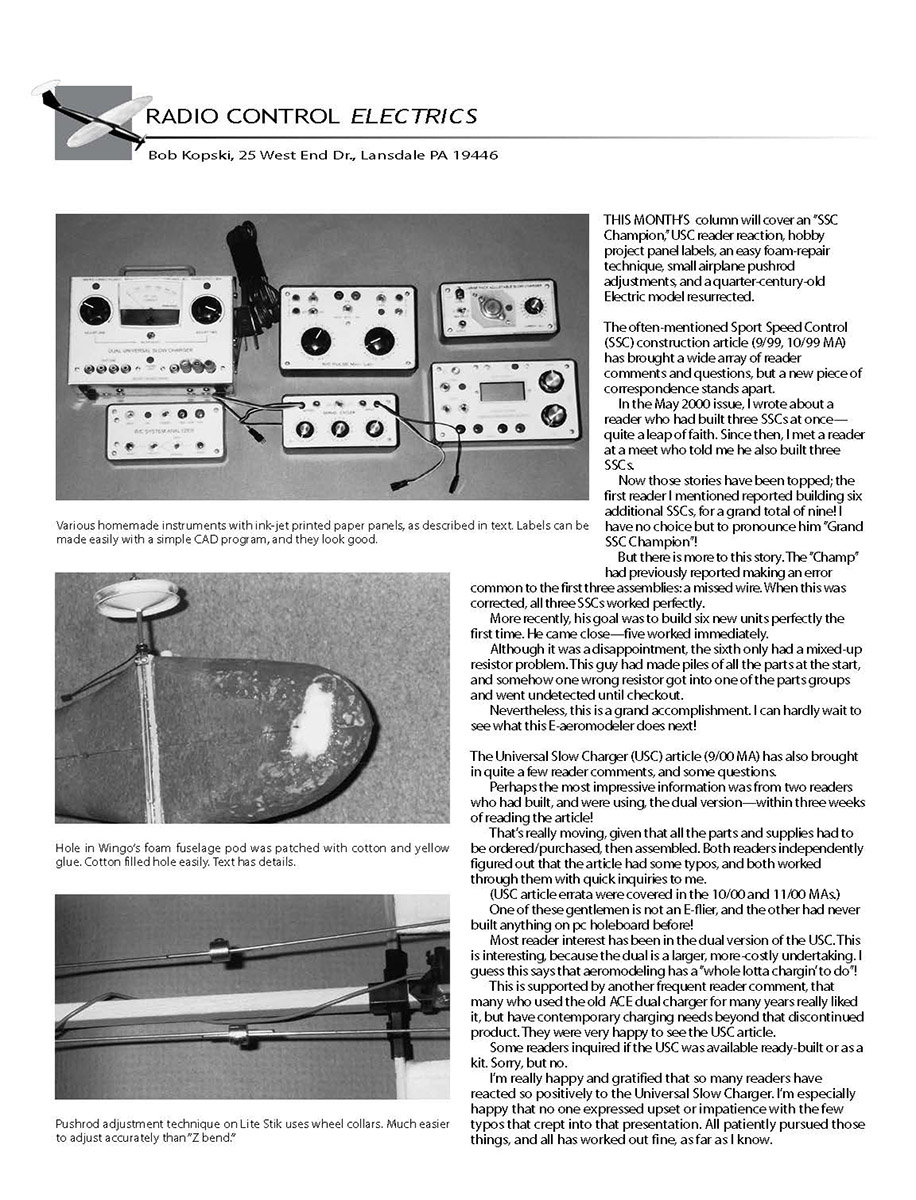
Hobby Project Panel Labels
Labels such as those in the USC and in other articles, like the Pulse Mini-Lab (6/98 MA) and the Servo Cycler (9/98 MA), add considerable appeal to homemade instruments and frequently bring reader inquiries. Since so many have asked, here's how I do it.
- Sketch a rough panel layout at the outset of a project—an initial arrangement of switches, knobs, connectors, etc.
- Follow that up with a more-serious, dimensioned layout on a personal computer. My software is TurboCAD by IMSI; I also use it for pc-board assembly drawings, schematics, and model-construction plans.
- Draw and print panel layouts full-size. I normally print two versions for each panel:
- Construction version: shows all drill centers and is used as a drilling template. Attach it to the metal panel (usually aluminum) by smoothing an Elmer's Glue Stick on the panel, positioning the paper pattern, then pressing it in place. Center-punch and drill the hole locations. Soak the panel and paper in warm, soapy water to dissolve the Elmer's, rinse, dry, and deburr the holes.
- Final label: printed on higher-quality paper with the mechanical details removed and the appropriate lettering added. Use the program's layer feature to manage content. Cut a few hole locations with a fresh X-Acto #11 blade, use these holes to align with the drilled panel holes, then glue the label in place with an Elmer's Glue Stick. Smooth it with finger pressure using a temporary cloth over the paper.
- Protect the printed label with clear contact paper. Sometimes make the paper label slightly undersize so the clear cover extends roughly 1/16-inch past the paper onto the aluminum. Finish by cutting out remaining label holes with the X-Acto at the drilled hole locations.
Visit turbocad.com to download a free, smaller demo version. It is fully workable and can open files from the full product. When I gave a friend copies of my SSC drawing files, he opened and printed them on the demo version and subsequently purchased the full software. It is economical and powerful, and transfers files with AutoCAD.
EMPS MGK Motor Kit and a Resurrected ZAP III
The MGK motor kit from EMPS, Inc. (Box 134, Robesonia PA 19551; web: www.empsinc.com) is an increasingly popular small power system that works very well. The kit consists of a small motor, gears, propeller shaft and bearing, and propeller. This $13.95 (plus postage) system is used with three to six cells.
I got one of these kits to try. After simple assembly work and a bench run, I needed something to put the motor in. Inspiration struck, and I remembered an old electric model I had up in the attic.
I dug around and recovered my 26-year-old ZAP III—all dirty, twisted, and "moused." ZAP III has history: it was my first electric model that actually climbed. Notes from 1974 indicate the model was powered by a Mattel toy motor/gears (no longer available) and it used a now-missing "super-regent" receiver with an Adams pulse actuator on rudder and motor control.
I recovered the well-aged, very warped Solarfilm-covered surfaces with MonoKote. I replaced wood where mice had munched and located the receiver assembly. A few days of repair got everything up and running. My rules of thumb, combined with weight and power measurements, showed I needed four Ni-Cd cells. This was a problem because the original installation was designed for three Ni-Cd pencils.
After some circuit modifications and a charge-up of my 1970 homebuilt six-meter Galloping Ghost transmitter, it was off to the field!
Since I didn't have elevator, the on/off motor control was crude, and I really didn't know what was going to happen. I used the old "limited charge" technique: roughly 20 seconds worth of motor run in the new four-cell 500 mA pack, and launched.
The ZAP III had good forward speed but steady sink. I added positive incidence, got less sink, added slightly more shim and some recharge, and up it went, wiggling all the way! What memories this rekindled.
In those days one had to work hard, with determination, to get an electric model to fly—not anywhere near the way things are now. But it was fun, and ZAP III is fun again. I've been flying ZAP III regularly, and I flew it at a meet. People are amazed at the pulsing rudder, the pulse-rate change to effect motor on/off, and the more-than-10-minute flights I'm getting with this 12-ounce, quarter-century-old airplane, receiver, and transmitter. The new EMPS MGK is doing a great job in this old, born-again attic find.
Easy Foam-Repair Technique
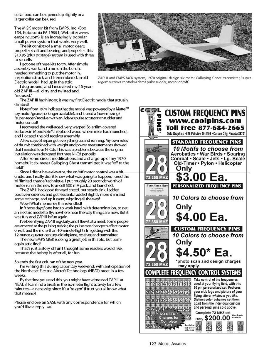
The Wingo from Hobby Lobby is an incredibly popular Almost Ready-to-Fly (ARF) electric model. The mostly-foam assembly notwithstanding, it is a rather robust airplane and relatively hard to damage. However, damage is possible. One local modeler landed a bit fast onto a small stone; the stone punched a hole in the bottom front of the fuselage pod roughly one inch by two inches.
This was not a balsa repair—the opening was crumbly foam. I soaked some cotton with Titebond yellow glue (carpenter's glue). The trick is to not use too much glue, but to soak the cotton wad thoroughly. I stuffed the glued cotton into the jagged foam opening, packed and smoothed it so it filled the void and blended into the rough perimeter. Drying took two full days, but the cotton/glue combo turned into one tough patch that seemed every bit as durable as the original foam structure.
I put an overcoat of five-minute epoxy on the bottom front of the pod for added durability; that area often encounters Mother Earth in a nose-down landing. This remedy has worked well so far. Next time I'll thin the yellow glue a bit with water and use a heat lamp to speed drying—this should produce an even better, quicker outcome.
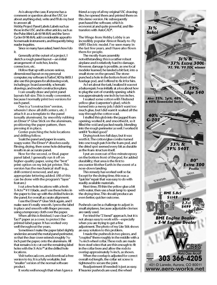
Small Airplane Pushrod Adjustments
Pushrods can be a challenge to adjust in small airplanes because adjustable clevises are rarely used. I've tried the "Z-bend" approach, but it's not always easy—especially when you need fine adjustment. An easy solution I use is to make the pushrods in two pieces and couple them roughly in the middle with a 1/16-inch wheel collar.
- Use steel wires thin enough to fit in the collar bore and allow the rods to overlap about 3/8 inch.
- Adjust the overlap for the correct overall rod length, then tighten the collar set screw to secure the joint.
- Readjustment, if needed, is easy—just loosen the set screw and move the rods.
- If heavier pushrods are used, the wheel collar bore can be opened up slightly or a larger collar can be used.
This method simplifies fine adjustments and is robust enough for most small-airplane applications.
Closing
That's just a story of fun I thought some readers would like—because the hobby is, after all, for fun.
So ends the first column of the new year. I'm writing this during Labor Day weekend with anticipation of the Northeast Electric Aircraft Technology (NEAT) meet in a few weeks. By the time you read this, you might have witnessed ZAP III at NEAT, if I can find a break in the six-meter flight activity for a few minutes—a necessity, since it's a "re-gen" (I trust you all know what that means)!
Please enclose an SASE with any correspondence for which you'd like a reply.
Transcribed from original scans by AI. Minor OCR errors may remain.

