
RADIO CONTROL ELECTRICS - 2001/02
Bob Kopski, 25 West End Dr., Lansdale PA 19446
This column will cover a meet announcement, the Electric Connection Service, some USC reader inputs, using LEDs, and writing to me.
Mid-Winter Electric Festival (meet announcement)
The Mid-Winter Electric Festival, presented by the Silent Electric Flyers of San Diego (SEFSD) for the past several years, is scheduled for February 16–18, 2001, at Mission Bay, CA.
Features:
- Presented by Hitec RCD, SEFSD, and Model Airplane News.
- Events and demonstrations, substantial prizes, supplier booths, and more.
- Two days of indoor flying in a nearby facility.
For more information:
- Web: www.sefsd.org
- Bill Everitt: (760) 753-1055; Fax: (760) 633-2271; E-mail: [email protected]
- Glen: (858) 747-6948 ext. 310
Tell ’em Bob sent you!
Electric Connection Service (ECS)
The Electric Connection Service is a free column feature intended to help E-modelers connect with other E-modelers in their vicinity.
- Dick Gum, 26828 Racquet Cir., Leesburg FL 34746-8083, is seeking others to help him get started in E-power.
The ECS generally works well, and I’m counting on this edition to work well too. Anyone anywhere who wants to be connected, just write me!
USC reader inputs — Slow Reactions
Readers continue to respond to the Universal Slow Charger (USC) construction article (9/00 MA) with stories of success and with some questions. Several readers have inquired about adding a peak detector to the USC.
Important points:
- The USC is a slow charger—no peak detector is needed or useful because there is no sharp voltage peak to detect in the usual sense.
- Fast-charge techniques (used for flightline charging) deliver high current and must be terminated precisely (timer or electronic peak detection) to avoid pack damage.
- Slow (overnight) charging is different. The commonly used rate is C/10 (one-tenth of the pack capacity). For example, a 500 mAh pack is charged at roughly 50 mA.
- At C/10, an empty Ni-Cd pack typically charges fully in about 14–16 hours. Because the current is low, a modest overrun of time does little immediate harm; this is unlike high-rate charging, where a few extra minutes can cause damage.
- With slow charging, there is no significant pack-voltage peaking at the full condition because internal temperature rise is slight. Therefore peak-detector termination is not effective or necessary for slow charging.
Time-switch option:
- If you want charging to end when slow charging is complete, a household timer can be used. Plug the timer into an outlet and plug the charger into the timer.
- Most hardware stores carry suitable timers; choose one that meets your needs.
Reader question:
- Will the pack discharge back through the USC circuitry when a timer shuts the charger off? No — the USC circuitry does not allow back-discharge through the charger when it is powered down.
LEDs — Recommended LED bias circuit (primer)
You have probably seen or used LEDs sometime in your life. Light-Emitting Diodes (LEDs) are solid-state lamps available in many colors, sizes, and package styles. They are rugged, long-lived, and efficient for visual indications.
NOTE: LED terminal "a" (anode) is the positive connection. It is typically the longer of the two LED leads. Terminal "c" (cathode) is the negative connection and is typically located near the flat on the base of round-cased LEDs.
Key principles:
- LEDs are diodes and have polarity (anode and cathode).
- Use LEDs by setting a current through them, not by attempting to set a fixed voltage across them. The current determines the voltage drop of the LED.
- Connecting an LED directly across battery cells is risky because small voltage changes produce large current changes.
- High-brightness LEDs can be painfully bright and are relatively costly, so current-limiting and proper biasing are important.
Bias circuit basics:
- A simple LED bias circuit consists of a battery (or pack), a series resistor, and the LED.
- Resistor value (ohms) = (Source voltage − LED forward voltage) / Desired LED current.
- Resistor power dissipation (watts) = Resistor voltage × LED current.
Example (my NiteLite):
- Power source: six-cell 500 mAh pack used as motor and receiver battery via BEC ESC. Average flight voltage ≈ 6.6 V.
- Typical LED forward voltage at 20 mA: ~2.0 V (values vary by color; blue/white often ≈3.0 V).
- If using one 2.0 V LED: resistor voltage = 6.6 − 2.0 = 4.6 V.
- Desired LED current = 20 mA = 0.02 A.
- Resistor value = 4.6 / 0.02 = 230 Ω. Standard values 220 Ω or 240 Ω are acceptable.
- Resistor power = 4.6 × 0.02 = 0.092 W (92 mW). A 1/4 W resistor is more than adequate.
Additional notes:
- For two 2.0 V LEDs in series: total LED voltage = 4.0 V, leaving enough voltage for a small resistor to stabilize current during pack voltage variation.
- Two 3.0 V LEDs in series (total 6.0 V) are close to the pack average of 6.6 V and leave too little headroom for a stable resistor-based current; avoid this for stable operation.
- When paralleling LEDs, give each LED its own current-limiting resistor to ensure even current sharing.
- White LEDs are blue LEDs with a phosphor coating and have forward voltages similar to blue LEDs (~3.0 V).
Practical results:
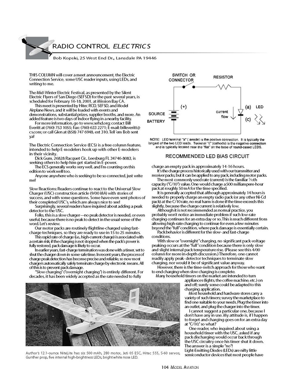
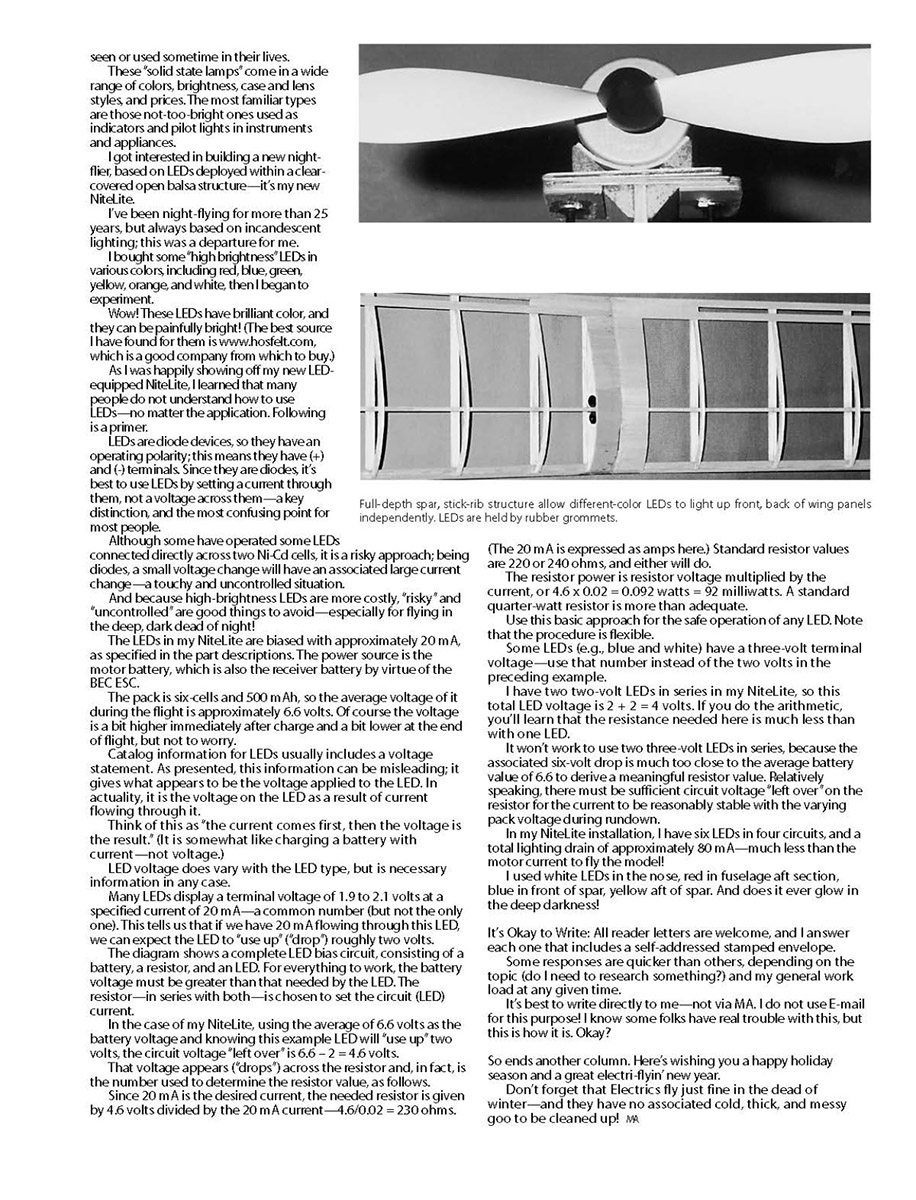
- In my NiteLite I used six LEDs in four circuits, total lighting drain ≈ 80 mA — much less than motor current.
- LED placement: white in the nose, red in fuselage aft, blue in front of the spar, yellow aft of the spar — produced a very bright night glow.
- Good source for high-brightness LEDs: www.hosfelt.com
Writing to me
All reader letters are welcome, and I answer each one that includes a self-addressed stamped envelope (SASE).
- Responses vary in speed depending on topic and my workload.
- Write directly to me — I do not use e-mail for this purpose.
So ends another column. Wishing you a happy holiday season and a great electr-i-flyin' new year.
Don't forget that electrics fly just fine in the dead of winter — and they have no associated cold, thick, and messy goo to be cleaned up!
MA
Transcribed from original scans by AI. Minor OCR errors may remain.

