
RADIO CONTROL ELECTRICS
Bob Kopski, 25 West End Dr., Lansdale, PA 19446
This column announces two meets, has helpful hints for the FMA Direct Razor and some related interference matters, and shares new reader input on the Universal Slow Charger.
Fifth Old Time Eagles All Electric Fly-In
- When: Saturday, May 12, 2001, 9 a.m.–4 p.m.
- Where: Near Hope, NJ
- Host: Old Time Eagles model airplane club
- Sponsor: Flying Models magazine (Gold Sponsor)
The fly-in is a fun-fly promoting all types of electric-powered models, including radio control (RC), free flight, modern, vintage, etc. One competitive event is planned: Elexaco. For complete meet information and a detailed description of the Elexaco event, send a self-addressed stamped envelope (SASE) to Contest Director Joe Beshar, 198 Merritt Dr., Oradell, NJ 07649. (Editor's note: Model Aviation will soon publish a complete description of the Elexaco event.)
An AMA license is required to participate. I attended last year and am eagerly looking forward to going again.
NEAT fair (Northeast Electric Aircraft Technology fair)
- When: September 14–16, 2001
- Where: Peaceful Valley Campgrounds, New York
- Sponsor/Manager: SEFLI—the Silent Electric Flyers of Long Island; managed in part by Tom Hunt of Modelair-Tech
The NEAT fair began in September 2000 as a follow-on to the long-running but discontinued KRC Electric Fly. Coverage of the inaugural affair appears in the February 2001 Model Aviation. Tom tells me this year's meet will be much like last year’s, with some modifications to field setup to better accommodate all attending—especially the expected growth. New this year will be a Saturday-night barbecue social on-site and some other goodies.
More info, photos, maps, and motel listings can be found at www.nyblimp.com/NEAT.htm. I encourage you to attend; I had a great time last year and am looking forward to this year’s meet.
FMA Direct Razor — my experience
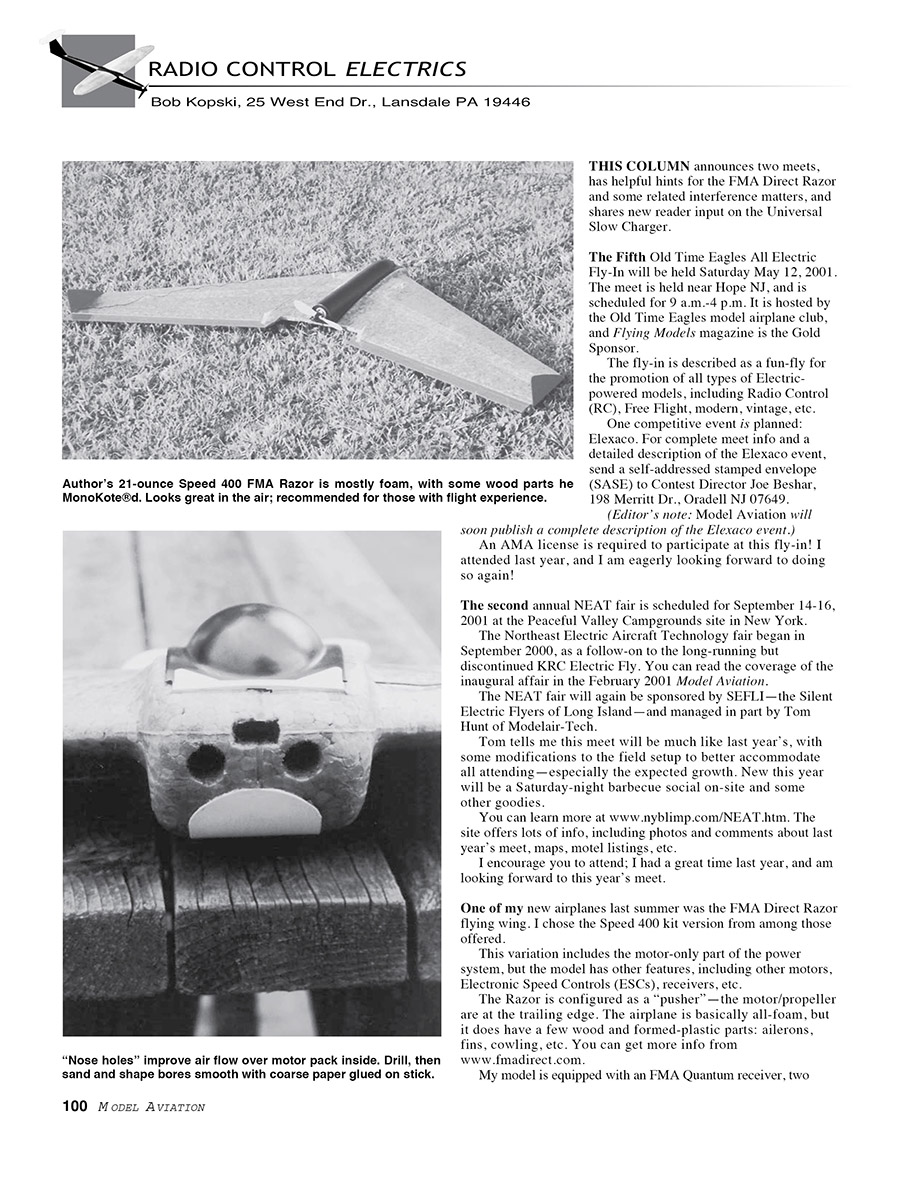
One of my new airplanes last summer was the FMA Direct Razor flying wing. I chose the Speed 400 kit version. This variation includes the motor-only part of the power system, but other motors, electronic speed controls (ESCs), receivers, etc., are available. The Razor is configured as a “pusher” — the motor/propeller are at the trailing edge. The airplane is basically all-foam, with a few wood and formed-plastic parts: ailerons, fins, cowling, etc. More info: www.fmadirect.com.
My model is equipped with an FMA Quantum receiver, two FMA S80 servos, seven 600AE cells, and a Pixie 14 ESC. I’m flying it direct-drive with a Gunter 5-1/4-inch propeller. All-up weight is 21.4 ounces.
The Razor flies with a certain “personality.” In the process of building and flying this airplane I learned some things that may be helpful.
Cooling the battery pack
Regular readers know I favor good airflow over a battery pack. Airflow won’t make much difference in airplanes flown very briefly at very high power, but cooling airflow can be beneficial for models flown more moderately with longer flights.
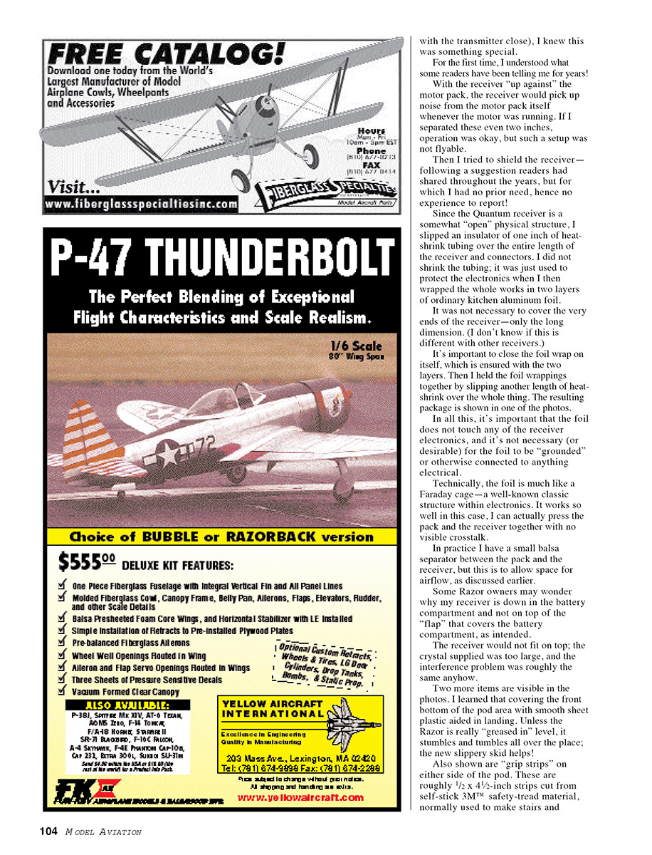
As designed, the Razor allows no cooling air to the pack. The pack is nested in a hot foam box and must be removed between flights for cool-down and recharge. Since I prefer not to remove packs unless necessary, I looked for a compromise.
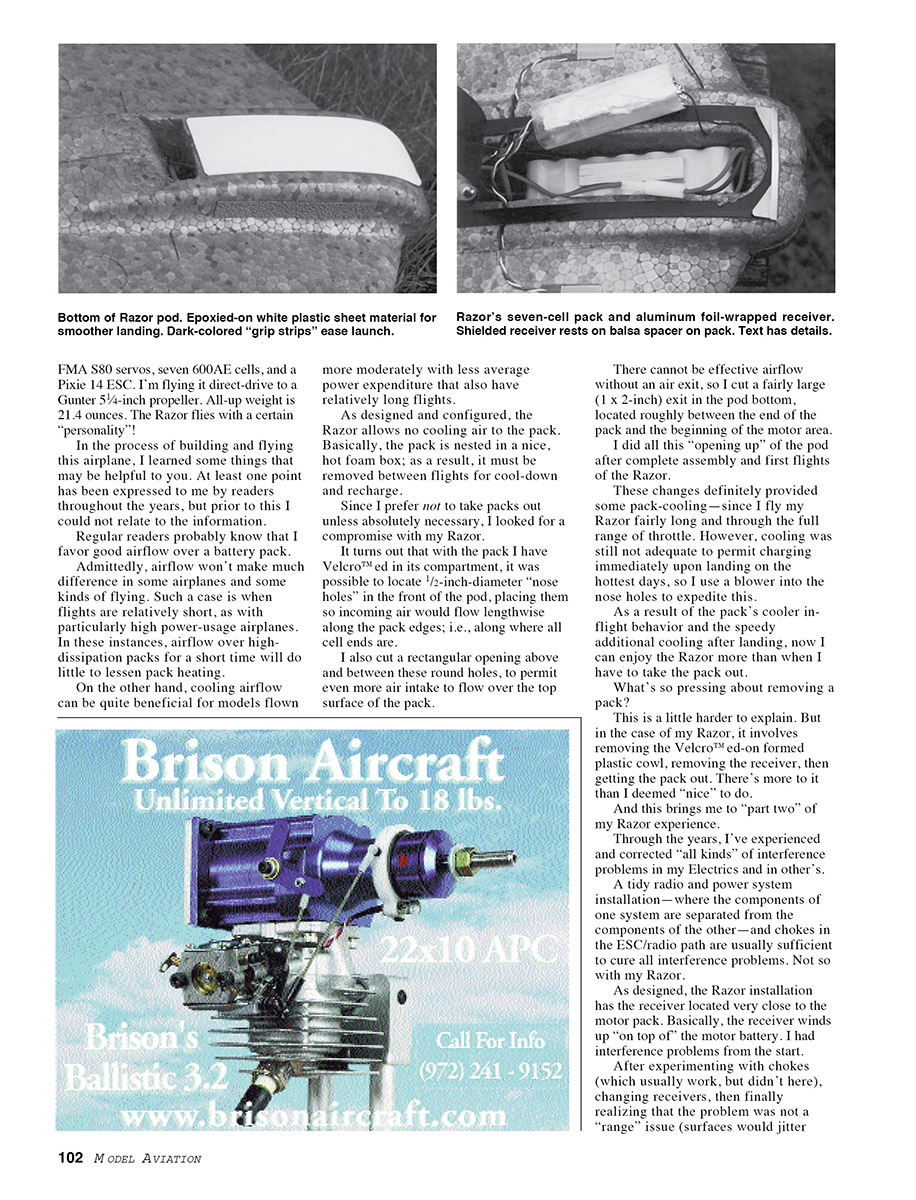
- I had the pack Velcroed in its compartment and located two 1/2-inch-diameter “nose holes” in the front of the pod so incoming air would flow lengthwise along the pack edges (along the cell ends).
- I cut a rectangular opening above and between these round holes to permit more air intake over the top surface of the pack.
- I cut a fairly large exit (about 1 x 2 inches) in the pod bottom, located roughly between the end of the pack and the start of the motor area, because effective airflow requires an exit.
I made these openings after completing assembly and first flights. These changes provided some pack cooling. On the hottest days cooling was still not adequate to allow charging immediately upon landing, so I use a blower into the nose holes to expedite cool-down. With inflight cooling and quick postflight cooling, I now enjoy flying the Razor more than when I had to remove the pack.
Removing the pack on this model is somewhat inconvenient: remove the Velcroed-on formed plastic cowl, remove the receiver, then get the pack out. That's more work than I like.
Interference and shielding
Over the years I’ve experienced and corrected many interference problems in electrics. A tidy radio and power-system installation—separating components and using chokes in the ESC/radio path—is usually sufficient. Not so with my Razor.
As designed, the receiver is located very close to the motor pack, essentially "on top of" the motor battery. I had interference problems from the start. After experimenting with chokes (which usually work, but didn't here), changing receivers, and finally realizing the problem was not a range issue (surfaces would jitter even with the transmitter close), I knew this was something special.
For the first time I understood what some readers have been telling me for years: with the receiver up against the motor pack, it would pick up noise from the pack whenever the motor ran. Separating them by even two inches helped, but such a setup was not flyable in the Razor’s layout.
I tried shielding the receiver as readers had suggested. The Quantum receiver is a somewhat open structure, so I slipped an insulator of one inch of heat-shrink tubing over the entire length of the receiver and connectors (I did not shrink the tubing). I then wrapped the whole assembly in two layers of ordinary kitchen aluminum foil. It wasn’t necessary to cover the very ends of the receiver—only the long dimension. Close the foil wrap on itself (two layers helps), then hold the foil in place with another length of heat-shrink over the whole thing. The result is a neat package.
Important points:
- The foil must not touch any of the receiver electronics.
- It is neither necessary nor desirable for the foil to be grounded or connected to anything electrical.
- The foil acts like a Faraday cage and works so well I can press the pack and receiver together with no visible crosstalk.
In practice I keep a small balsa separator between the pack and the receiver to allow some airflow.
Some Razor owners may wonder why my receiver is down in the battery compartment and not on top of the battery flap, as intended. The receiver would not fit on top because the supplied crystal was too large, and the interference problem was roughly the same there.
Other small modifications
- Skid: A skid glued to the front bottom of the pod, with smooth sheet plastic, helps landings. Unless the Razor is greased in level, it can stumble and tumble; a slippery skid helps.
- Grip strips: I glued 1/2 x 4-1/2-inch strips cut from self-stick 3M safety-tread material (used to make stairs and walkways slip-proof) on either side of the pod. This material is available at hardware stores and works well as skid material for glider bottoms. It also makes hand-launching easier because you don't have to squeeze the foam pod as hard.
My Razor is a bit spirited and displays in-air personality, so I feel it’s not suited for very inexperienced fliers. This was my first RC electric wing configuration and it’s been a good education.
Universal Slow Charger — reader feedback
Readers continue to send comments and queries about the Universal Slow Charger (9/00 Model Aviation). Several points and questions have come up:
- Connector styles: No, you do not have to use the multiple-output connector strips I used. Many readers have substituted alternate connectors (for example, banana connectors) to suit their preferences. Use any connector style that fits, but make sure there is no metallic connector contact with the metal case.
- Missing jumpers: A few readers missed the jumper wires that are on top of the holeboard, but underneath the IC sockets. They found and corrected this by installing the jumpers on the bottom (conductor) side of the holeboard. Just be sure these repair wires do not contact lands they are not supposed to.
- Fit of parts: Contrary to one reported experience, the specified wire and IC socket pins do fit in the holeboard holes as shown—use the specified parts and material.
- "#55" drill: Some readers did not understand the "#55" drill called out on the assembly drawings. Common fractional drill sets are familiar to many modelers, but there are also numbered drill sets. Numbered sets often go #1 through #60 (and #61–#80 in another set). A #1 bit is 0.228 inch, and a #80 is 0.0135 inch. A #55 bit is 0.0520 inch in diameter—just right for the component leads that need to go in it and small enough to avoid breaking the PC board lands. Most good hardware stores sell numbered drill bits individually and in sets. There are also lettered and metric sets—choose the hole size for your need.
Please enclose an SASE with any correspondence for which you want a reply. I respond to every letter I receive that is accompanied by an SASE. If you sent one and have not received a reply, I did not get what you sent (this happened to one reader).
Happy and numerous E-landings, everyone!
MA
Transcribed from original scans by AI. Minor OCR errors may remain.

