
RADIO CONTROL ELECTRICS
Bob Kopski, 25 West End Dr., Lansdale PA 19446
THIS COLUMN OFFERS one meet announcement, describes an electric built to meet a design challenge, and reviews a variety of new and classic reader questions.
Event announcement
Colin McKinley—an E-modeler friend from long ago—wrote to announce an Electric funfly hosted by the Riverside Aero Modelers. It is scheduled for August 23–24 in King, North Carolina (near Winston-Salem). Not all details were finalized when this was written, but they should be by the time you read it.
- Contest Director: Randy Covington — (336) 983-9126
- Email: [email protected]
- Colin McKinley: 4003 Poindexter Ave., Winston-Salem NC 27106
When you see Colin at the meet (he'll be the guy flying numerous vintage RC E-conversions), be sure to tell him Bob sent you!
Design challenge: Stikum
As described in recent columns, last summer I noticed the special difficulties would-be electric aeromodelers can face when getting started—many problems stem from products sold as Almost Ready-to-Fly (ARF) "trainers" that were anything but. Trying to help some people in this situation and reflecting on more than 40 years of watching first-timers, I set myself a fun design challenge: produce a compromise beginner's design that addresses common early-flight problems.
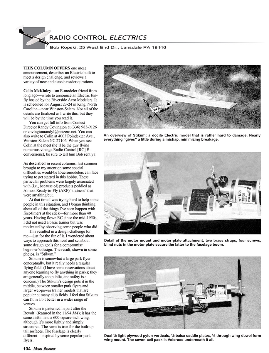
The result is "Stikum." Conceptually it is somewhat a large park flyer, but it really needs a regular flying field (I have reservations about first learning in parks; they are often too public and safety is a concern). Stikum sits between smaller park flyers and larger glow-powered trainers popular at many club fields, so it can fit a wider range of venues.
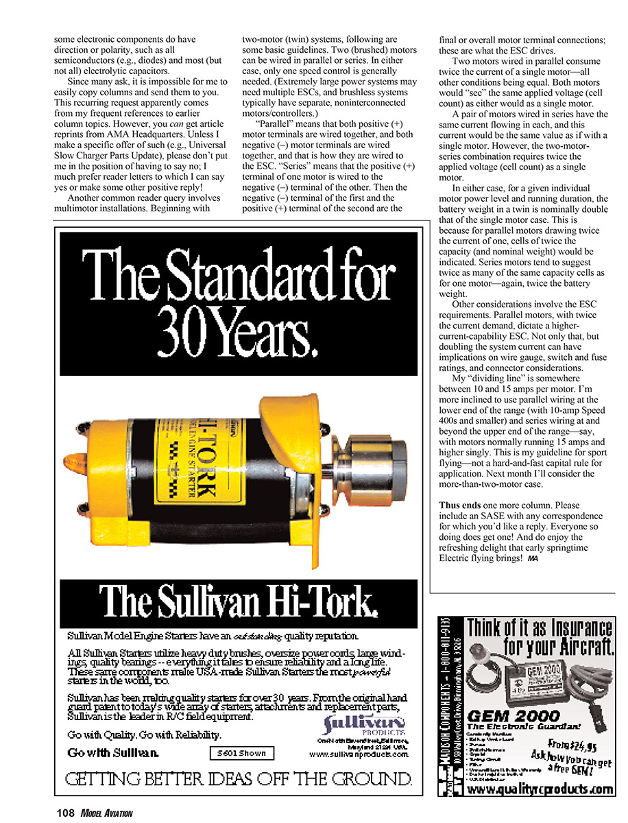
Stikum is patterned in part after the Revolt! (featured in the 11/94 MA): it uses the same airfoil and a 600-square-inch wing but is more lightly and simply structured. The built-up tail surfaces are similar, but the fuselage is clearly different—partly inspired by some popular park flyers. A simple connector set serves as airplane wiring and also functions as the "switch"; everything is powered when the pack is plugged in.
Construction and component choices
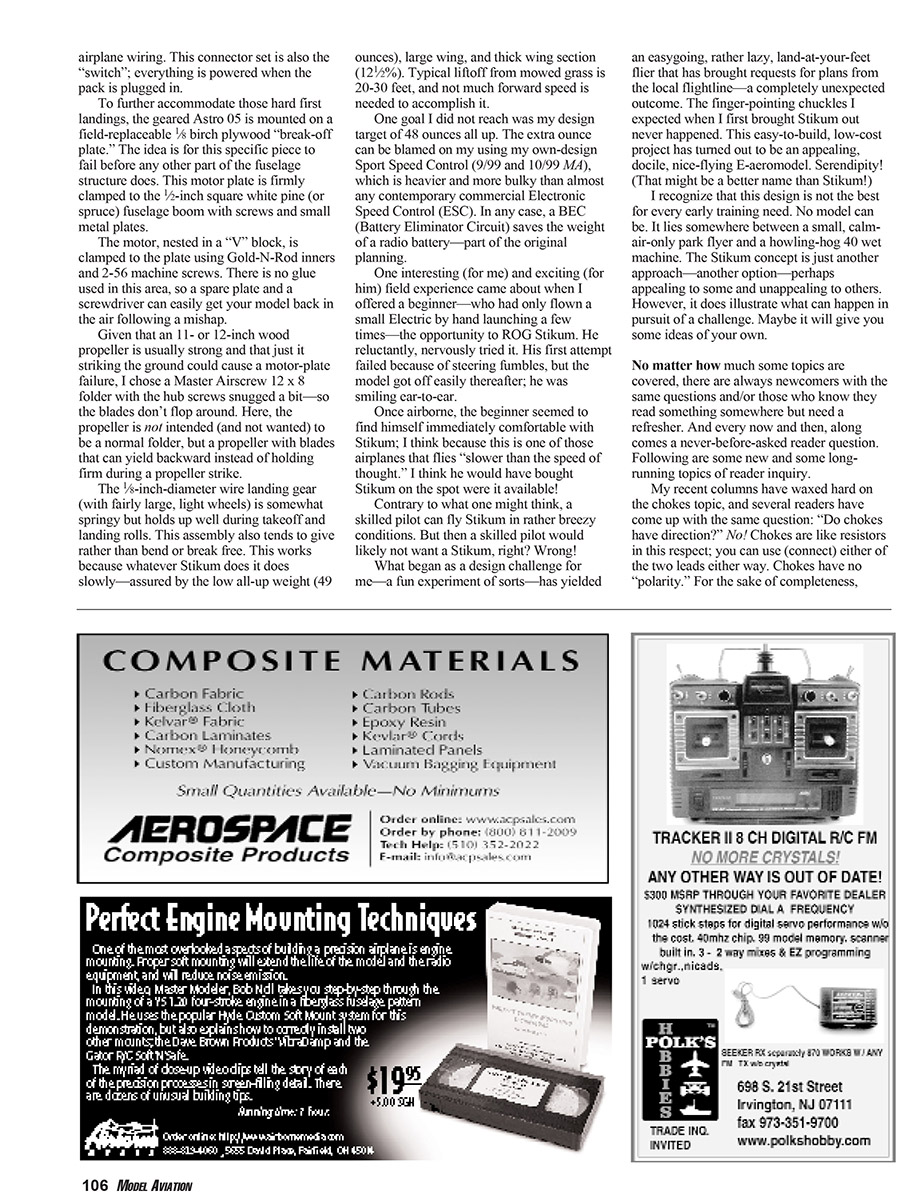
- To accommodate hard first landings, the geared Astro 05 motor is mounted on a field-replaceable 1/8" birch plywood "break-off plate." The idea is for this piece to fail before any other fuselage structure does. The motor plate is firmly clamped to the 1/2" square white pine (or spruce) fuselage boom with screws and small metal plates.
- The motor is nested in a "V" block and clamped to the plate using Gold-N-Rod inners and 2-56 machine screws. No glue is used in this area, so a spare plate and a screwdriver can easily get your model back in the air following a mishap.
- Because an 11"–12" wood propeller is usually strong and striking the ground could still cause motor-plate failure, I chose a Master Airscrew 12 x 8 folder with the hub screws snugged a bit so the blades don't flop. Here the prop is not intended to act as a normal folder but to allow blades to yield backward on a strike.
- The 5/8" diameter wire landing gear (with fairly large, light wheels) is somewhat springy and tends to give rather than bend or break. This complements Stikum's slow, gentle behavior.
- Stikum's all-up weight is 49 ounces, with a large wing and a thick wing section (about 12.5%). Typical liftoff from mowed grass is 20–30 feet; not much forward speed is needed.
- One design target I missed was 48 ounces all-up. The extra ounce is largely due to my using my own-design Sport Speed Control (9/99 and 10/99 MA), which is heavier and bulkier than most contemporary commercial ESCs. A BEC (Battery Eliminator Circuit) saves the weight of a radio battery—part of the original planning.
Flight experience and reception
One memorable field experience: I offered a beginner—who had only hand-launched a small electric a few times—the chance to ROG (rise off ground) Stikum. He was reluctant and nervous. His first attempt failed because of steering fumbles, but the model got off easily thereafter and he was smiling ear-to-ear. Once airborne he seemed immediately comfortable with Stikum; it flies "slower than the speed of thought." He likely would have bought one on the spot if they were available.
Contrary to what one might think, a skilled pilot can fly Stikum in rather breezy conditions. What began as a personal design challenge has yielded an easygoing, lazy, land-at-your-feet flier that attracted requests for plans at the local flightline—an unexpected outcome. The finger-pointing chuckles I expected never happened. This easy-to-build, low-cost project is an appealing, docile, nice-flying electric aeromodel. Serendipity might even be a better name than Stikum!
I recognize this design is not the best for every early training need. No model can be. It lies between a small, calm-air-only park flyer and a loud 40-size wet machine. Stikum is just another approach—another option that may appeal to some and not to others. Perhaps it will give you ideas of your own.
Reader questions and clarifications
My recent columns have covered chokes extensively, and several readers asked the same question: "Do chokes have direction?" No. Chokes are like resistors in this respect; you can use either lead either way. Chokes have no "polarity." For completeness: some electronic components do have direction or polarity, such as all semiconductors (e.g., diodes) and most (but not all) electrolytic capacitors.
Many readers ask for copies of past columns. It's not easy for me to copy and mail columns on request. You can obtain article reprints from AMA Headquarters. Unless I specifically offer a reprint (for example, "Universal Slow Charger Parts Update"), please don't put me in the position of having to say no; I much prefer reader letters I can answer directly or positively.
Please include a stamped, self-addressed envelope (SASE) with any correspondence for which you'd like a reply. Everyone who does so receives one.
Multimotor installations (basic guidelines)
Beginning with two-motor (twin) systems, here are some basic points for brushed-motor installations. (Extremely large power systems may need multiple ESCs; brushless systems typically have separate, non-interconnected motors and controllers.)
- Parallel wiring:
- Both positive (+) motor terminals are wired together and both negative (–) terminals are wired together; those two combined terminals connect to the ESC.
- Both motors see the same applied voltage (same cell count) as a single motor would.
- Current draw is twice that of a single motor (all else equal), so the ESC must handle the higher current; wire gauge, switch and fuse ratings, and connectors must also be upgraded.
- For battery weight: parallel motors typically indicate cells of twice the capacity (and nominal weight) for a given run time.
- Series wiring:
- The positive (+) terminal of one motor is wired to the negative (–) terminal of the other. The remaining negative of the first motor and positive of the second become the overall motor terminals the ESC drives.
- The same current flows through both motors, and that current equals the single-motor current.
- The required applied voltage (cell count) is doubled compared to a single motor.
- For battery weight: series motors tend to require twice as many of the same-capacity cells as for one motor—again, roughly doubling battery weight.
Other considerations: parallel motors with twice the current demand need a higher-current-capacity ESC; doubling system current affects wire gauge, switch/fuse ratings, and connector choices.
My practical guideline (not a hard-and-fast rule) is a dividing line somewhere between 10 and 15 amps per motor. I'm more inclined to use parallel wiring at the lower end (for 10-amp Speed 400s and smaller) and series wiring at and beyond the upper end (motors normally running 15 amps and higher singly). This is my guideline for sport flying. Next month I'll consider more-than-two-motor installations.
Thus ends one more column. Do enjoy the refreshing delight that early springtime electric flying brings! MA
Transcribed from original scans by AI. Minor OCR errors may remain.

