


RADIO CONTROL ELECTRICS
Bob Kopski 25 West End Dr., Lansdale PA 19446
Introduction
This column shares some reader reaction to Dump’r and continues the topic of basic electrical terms and concepts which began last month.
I introduced Dump’r in the June column with a photo and a brief description. It is a versatile, home-brew battery discharger I developed for my own use. It is intended to safely discharge 4- to 18-cell motor packs which I’ve charged for flight but did not use (I prefer not to store charged packs for a variety of reasons). The discharge current is a constant 500 mA. As I described, I intended to build more of them, and now I have four Dump’rs in use.
As I write this, several weeks have passed since the June issue came out, and reader reaction to Dump’r has been amazing. Everyone who wrote requested that I make it available to all. Given the substantial reaction, I have begun a construction article that MA will publish in next month’s issue. Thanks to all of you for showing so much interest and support!
I introduced the topic of electrical terms and concepts last month, and it will continue now and in the future. This offering is in response to a slow but steady flow of reader mail throughout the years indicating the continuing need for basic electrical information, understanding, and "how to."
Last month’s discussion was an attempt to convey a feel for terms and concepts such as voltage, current, and power. This even included taking liberties with the pure technical definition of these and related terms—solely for the purpose of making the topic more comfortable. This theme continues now.
Fortunately, all common electrical parameters are easy to measure, and almost anyone can do so with minimal investment and some insight. Having interest and ability in this area can make electric power all the more enjoyable for those who want to pursue such detail. On the other hand, it is unnecessary to get into this stuff to enjoy electric flight; consider that the equivalent is unavailable to the wet-power crowd. It’s similar to computers: some use them as tools and others know all about what makes them tick.
Voltage and Multimeters
Let’s begin again with voltage. It is physically measured with a voltmeter, but nowadays one can be hard-pressed to find a simple standalone voltmeter. It’s far more common, convenient, and practical to use a "multimeter." Multimeters are "many meters" (i.e., many meter functions) in one box. They typically include:
- a voltmeter,
- a current meter (ammeter),
- an ohmmeter (resistance meter),
- and sometimes other less-familiar functions.
Function selection is usually made by switch settings and/or multimeter terminal connections.
There are two kinds of multimeters: the classic analog ("moving needle") and the contemporary digital counterpart. The former are getting harder to buy, but there are still present-day applications for which many prefer them (trend measurements are easier to see with analog meters). Digital multimeters (DMMs) display a measurement result numerically, eliminating the need to interpret an analog needle position. Digital meters typically offer greater reading resolution (more significant digits) than an analog meter can.
Economy DMMs are so pervasive now that they can be found at many local stores such as RadioShack, hardware and auto-parts places, and often at variety stores. It should be easy for most E-aeromodelers to have a suitable instrument.
One photo shows several analog and digital multimeters, a panel analog ammeter, and the AstroFlight Whattmeter, which I will discuss in the future. Other photos show multimeters in comparative application.
Measuring Voltage
Recall that voltage is electrically what appears at your household outlets, the auto-battery terminals, and at the terminals of your radio and motor batteries. Voltage sources never have current flow from them unless something (a "load") is connected. Your flashlight battery has only voltage and no current present while the flashlight is off.
Anyone can measure a voltage level by switching a multimeter to the "voltage" function and connecting the two meter leads to the unknown voltage-source terminals. But to do so properly requires one more determination: that of choosing the meter "range."
Most metering functions within a multimeter have several ranges or scales from which to select. A range is the full-scale value that can be displayed, and analog and digital meters both have ranges.
Common full-scale ranges found in the voltmeter portion of DMMs include:
- 200 millivolts (0.2 V)
- 2 volts
- 20 volts
- 200 volts
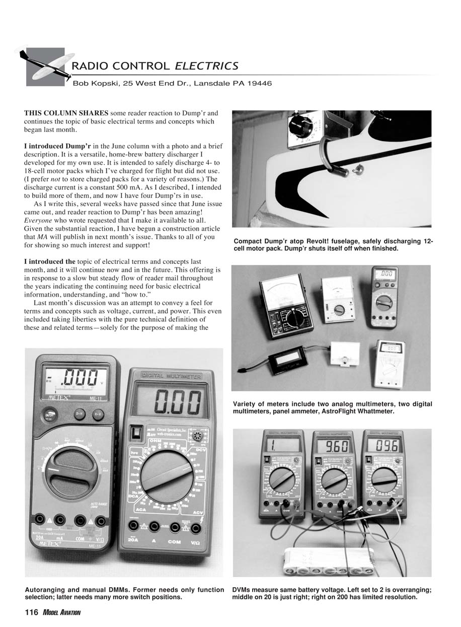
Although these are typical, other full-scale values are also common. Manual meter-range selection is usually made with a simple rotary switch, although some DMMs feature "autoranging." Autoranging requires the operator to select the function (volts, amps, etc.), then the meter adjusts itself for the proper range once a measurement commences.
Some DMMs offer operator choice; you can choose "manual" or "autorange" modes of operation. Several versions are shown in the photos. I generally prefer the "fully manual" (non-autoranging) version, at least for beginning hobbyists.
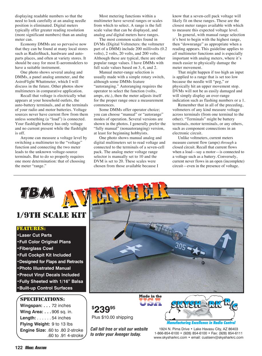
One photo shows manual analog and digital multimeters set to read voltage and connected to the terminals of a seven-cell pack. The analog meter voltage range selector is manually set to 10 and the DVM is set to 20. These scales were chosen from those available because I know that a seven-cell pack voltage will likely fit on these ranges. These are the closest meter ranges available with which to measure this expected voltage level.
In general, with manual range selection it's best to begin with the highest range, then "downrange" as appropriate when a reading appears. This guideline applies to all multimeter functions and is especially important with analog meters, where it's much easier to physically damage the meter movement.
That might happen if too high an input is applied to a range that is set too low because the needle will "peg," or physically hit an upper movement stop. DMMs will not be as easily damaged and will simply display an over-range indication such as flashing numbers or a leading 1.
Remember that voltmeters of any kind measure voltage across terminals (from one terminal to the other). "Terminals" might be battery terminals, motor terminals, or any others, such as component connections in an electronic circuit.
Current and Ammeters
Unlike voltmeters, current meters measure current flow (amps) through a closed circuit. Recall that current flows when a load—say a motor—is connected to a voltage such as a battery. Conversely, current never flows in an open (incomplete) circuit—even in the presence of voltage.
The unit of measure for current is amps. Current is measured with an ammeter, and it could be an individual panel meter movement (such as the one in the photo) or a multimeter's current function.
The most important point is that current meters are connected in series with the voltage source and the load. The meters are displaying the current flowing in the path; i.e., from the battery through the meters to the load. This is a closed circuit: a necessity for any current to flow.
Never connect a current meter across a voltage source!
Voltmeters vs. Ammeters (Input Resistance and Burden)
Now that I am discussing two entirely different kinds of measurement meters (voltmeters and current meters), another fundamentally important distinction can be made: a voltmeter is typically a high-resistance device. That means a good voltmeter takes ("steals") little current from the device or circuit under test, to minimally disturb or influence the true value being measured.
Ideally a voltmeter would have infinite resistance and would take no current while making a reading. Most DMMs (DMMs set to the voltmeter function) have a 10-megohm (10 million ohms) input resistance.
On the other hand, a good current meter has low resistance, and when it's connected in a closed-circuit path it uses up little of the total available voltage. This is sometimes called ammeter "insertion loss" or "burden." Ideally an ammeter would have zero resistance and thereby introduce no loss when in place in a circuit.
Putting it yet another way, an ideal current meter would require no voltage on its own terminals to operate. This is the "dual" of the voltmeter case: the ideal current meter would "take" no voltage and the ideal voltmeter would "take" no current.
In practice, all current meters have some burden, and in the case of DMMs this is often equal to or slightly higher than the multimeter's lowest scale voltage. Thus most DMM current functions require (use) approximately 0.2 volts for a full-scale current reading.
That is, if a current meter were indicating a reading of full-scale value (on any range), it would be "robbing" about 0.2 volts of the voltage available within a circuit path. This would have the same effect as lowering the source voltage by this amount. Later in this discussion series I'll examine why this is so and how and why the insertion loss of a current meter may sometimes be significant to E-aeromodellers.
Demonstration Circuit
One photo shows a seven-cell pack, one of each current-meter type, and a load resistor—all connected in series, or "daisy chain" fashion. The load could just as easily be a motor, a light bulb, or some electronic device such as a radio.
The resistor in this demonstration circuit is 510 ohms. The expected current (voltage divided by resistance) is roughly 9 divided by 510, or approximately 0.018 amps (18 milliamps, mA). ("Milli" means 1/1000.)
As in the voltmeter case described earlier, a suitable ammeter range needs to be selected. An autoranging DMM will do this automatically, but manual multimeters should be set to a high-value range before a test connection is made. In the example shown, the analog multimeter is set to the 50 mA scale (range), and the DMM is set to the 20 mA (0.02 A) range.
Closing
This topical discussion will continue in upcoming columns. For now, do remember that voltmeters are connected across terminals, and current meters (ammeters) are connected in series with the circuit path.
Thus ends another column. Please enclose a self-addressed, stamped envelope with any correspondence for which you'd like a reply. Everyone so doing does get one. Happy summertime electric landings, everyone! MA
Transcribed from original scans by AI. Minor OCR errors may remain.

