

RADIO CONTROL ELECTRICS — November 2003
Bob Kopski 25 West End Dr., Lansdale PA 19446
This column announces one meet, offers two Electric Connection Service (ECS) entries, describes a mishap you'll want to avoid, recommends a growing E-resource, and continues the ongoing discussion of basic electrical terms, concepts, and how-tos.
Meet announcement — Fourth Annual Southwest Florida All‑Electric Event
Don McGillivray, 13371 Sylvan Ave., Fort Myers FL 33919; Tel.: (239) 481-0063, wrote about the Fourth Annual Southwest Florida All‑Electric Event, Saturday–Sunday, November 8–9, 2003, in Cape Coral, Florida. The Cape Coral R/Sea Hawks sponsors the meet; club Web site: www.rseahawks.org.
Site features: a 500-foot paved runway, grass within a large open field, shelters, and unlimited parking. Sunday noon is the time for an All‑Up/Last‑Down event (the only event listed on the mailer). The mailer includes detailed driving directions; you can request a copy from Don. Be sure to tell him Bob sent you.
Electric Connection Service (ECS)
Contacts seeking E-fliers in their areas:
- Jack Green, 2914 Yale Dr., Janesville WI 53548; Tel.: (608) 754-6335; E‑mail: [email protected]. Jack recently moved to this location and is eager to find E-others. He is a member of a largely wet‑power club and would like to find more people nearby who enjoy electrics.
- Jim Samuel, 81 Meer Dr., Upper Holland PA 19053; Tel.: (267) 994-3195; E‑mail: [email protected]. Jim is a newcomer to radio control and is interested in E‑power; he wants to hook up with other E‑fliers in his area.
E‑fliers in Jack’s and Jim’s vicinities can get in touch with them to share the quiet joy of E‑power. If you are seeking E‑association in your area, please use this ECS: send me all relevant info and I’ll include it in a future column. The ECS is available free to individuals and clubs.
Mishap: watchband shorting and burn warning
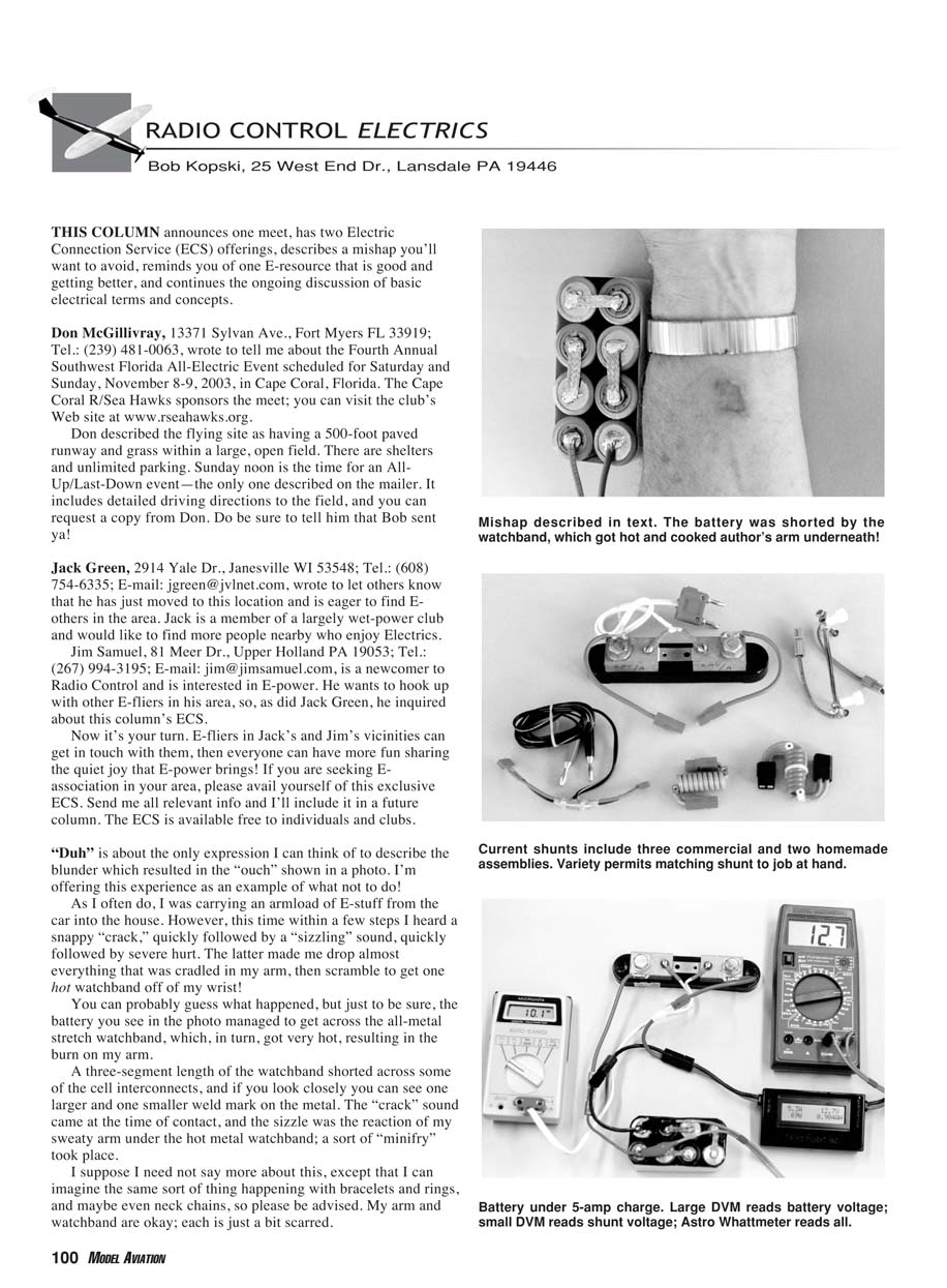
A cautionary tale: while carrying an armload of E‑stuff, a battery contacted my all‑metal stretch watchband. I heard a sharp “crack,” then a sizzling sound, followed by a painful burn that made me drop almost everything and remove the hot watchband.
What happened: a three‑segment length of the metal watchband shorted across some battery cell interconnects. You can see one larger and one smaller weld mark on the metal where contact occurred. The “crack” was at the moment of contact; the sizzle was my sweaty arm under the hot metal — a sort of “minifry.” My arm and watchband are okay but a bit scarred.
Be advised: the same sort of thing can happen with bracelets, rings, and neck chains. Avoid wearing conductive jewelry when handling batteries.
Recommended resource — Quiet Flyer
Quiet Flyer magazine is an excellent E‑resource. Each issue typically contains material ranging from beginner topics to heavy technical articles. Regular columnists and individual contributors provide reviews, how‑tos, meet coverage, and more. It’s a worthwhile magazine; consider buying it. Check the ad in Model Aviation or contact Quiet Flyer at (866) 627-0456.
Basic electrical terms, metering, and current shunts
Recent columns (August–October) have discussed basic electrical terms and concepts: voltage, current, and how they combine (multiply) to produce power. There was also discussion of measurement techniques and some dos and don’ts with common multimeters.
Key metering points:
- Voltmeters are always connected across device terminals (for example, across a battery, motor, or other component).
- Ammeters are always connected in series within a closed circuit.
Because many model power systems operate with relatively high currents, using a multimeter’s ammeter function directly can be problematic. It is often better to use a current shunt and read the shunt voltage with the voltmeter part of a digital multimeter (DVM). Last month’s graphic illustrated this approach.
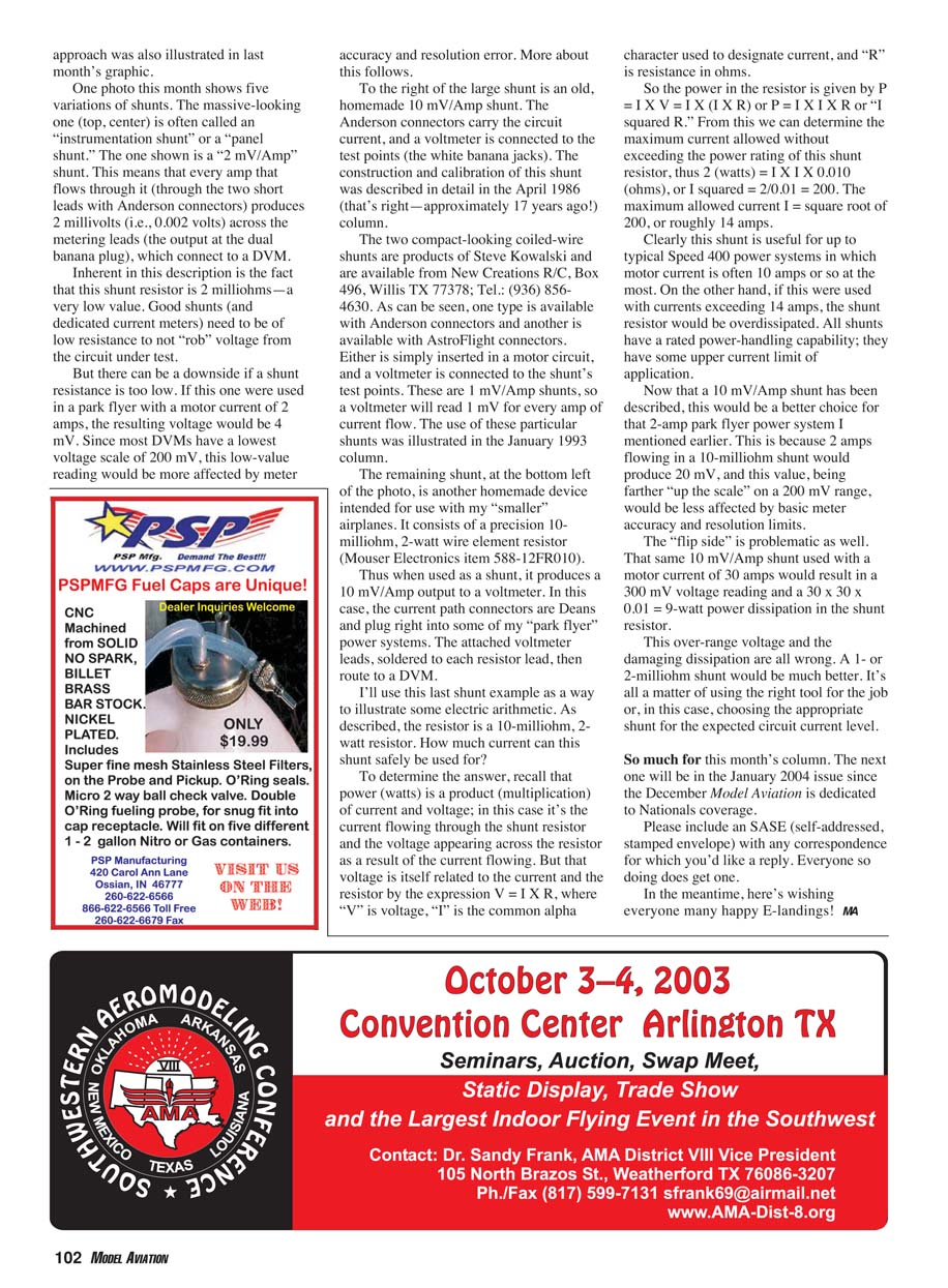
#### Current shunts — examples and discussion This month’s photo (not shown here) displayed five shunt variations:
- Instrumentation (panel) shunt — described as a 2 mV/Amp shunt. Every amp flowing through it produces 2 millivolts (.002 V) across the metering leads that connect to a DVM. This shunt’s resistor is 2 milliohms — very low resistance. Low resistance is desirable so the shunt does not rob voltage from the circuit under test. However, for low currents (e.g., 2 A), the resulting voltage (4 mV) may be below practical DVM ranges (most DVMs have a lowest voltage scale of 200 mV) and thus subject to accuracy and resolution errors.
- Old homemade 10 mV/Amp shunt — uses Anderson connectors for the circuit current and white banana jacks for the voltmeter test points. Construction and calibration were described in the April 1986 column.
- Two compact coiled‑wire shunts (Steve Kowalski, New Creations R/C, Box 496, Willis TX 77378; Tel.: (936) 856-4630) — available with Anderson or AstroFlight connectors. These are 1 mV/Amp shunts: a voltmeter reads 1 mV per amp of current flow. Their use was illustrated in the January 1993 column.
- Homemade 10‑milliohm, 2‑watt shunt (bottom left of photo) — built from a precision 10 mΩ, 2 W wire‑element resistor (Mouser Electronics item 588-12FR010). The Deans connectors carry circuit current; the voltmeter leads are soldered to each resistor lead and route to a DVM. This shunt produces 10 mV for every amp (10 mV/A).
Shunt arithmetic example (10 mΩ, 2 W shunt):
- Power in a resistor: P = I × V and V = I × R, so P = I^2 × R.
- For a 2 W rated shunt with R = 0.01 Ω (10 mΩ): 2 = I^2 × 0.01 → I^2 = 200 → I ≈ 14 A.
- Thus, this shunt is useful up to about 14 A (suitable for many Speed 400 systems that draw ~10 A).
- For a park flyer drawing 2 A, the 10 mΩ shunt produces 20 mV, which is a better reading on the 200 mV DVM range than a 1 mV/A or 2 mV/A shunt would produce.
- Conversely, using the 10 mΩ shunt at 30 A would produce 300 mV and dissipate 9 W (30^2 × 0.01), exceeding the shunt’s rating and likely causing damage. For high currents, a 1–2 mΩ shunt is more appropriate.
The takeaways: choose a shunt with an appropriate mV/A rating and power rating for the expected circuit current; use the proper tool for the job.
Closing notes
- The next column will appear in the January 2004 issue (the December Model Aviation is dedicated to Nationals coverage).
- Please include an SASE (self‑addressed, stamped envelope) with any correspondence for which you'd like a reply. Everyone who does so will get one.
- Many happy E‑landings!
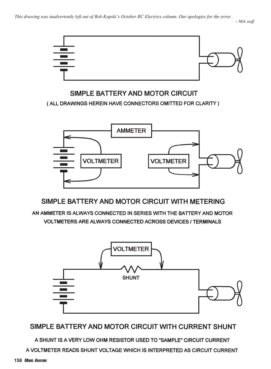
MA staff note: This drawing was inadvertently left out of Bob Kopski’s October RC Electrics column. Our apologies for the error.
SIMPLE BATTERY AND MOTOR CIRCUIT
(All drawings herein have connectors omitted for clarity)
SIMPLE BATTERY AND MOTOR CIRCUIT WITH METERING
- An ammeter is always connected in series with the battery and motor.
- Volt meters are always connected across devices / terminals.
SIMPLE BATTERY AND MOTOR CIRCUIT WITH CURRENT SHUNT
- A shunt is a very low ohm resistor used to "sample" circuit current.
- A voltmeter reads shunt voltage which is interpreted as circuit current.
Transcribed from original scans by AI. Minor OCR errors may remain.

