
RADIO CONTROL ELECTRICS
Bob Kopski, 25 West End Dr., Lansdale PA 19446
This column includes follow-up on two airplanes discussed in the January column, adds a third, and discusses more reader experience with Dump’r, including the related use of ohmmeters for checkout as part of the continuing "electrical terms and concepts" miniseries.
Skyvolt and Ruckus follow-up
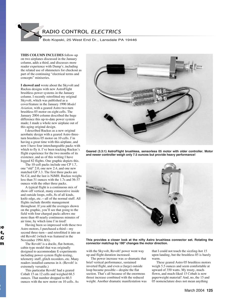
I showed and wrote about the Skyvolt and Ruckus designs with new AstroFlight brushless power systems in the January column. I recently retrofitted my original Skyvolt (published as a cover/feature in the January 1990 Model Aviation) with a geared Astro two-turn brushless 05 motor on eight cells. The January 2004 column described the huge difference this up-to-date power system made; I effectively made a whole new airplane out of this aging original design.
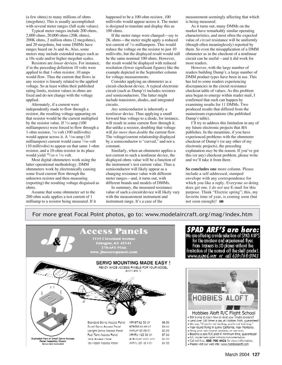
Ruckus is a new original aerobatic design with a geared Astro three-turn brushless 05 motor on 10 cells. I’m having a great time with this airplane, and now I have four interchangeable packs with which to fly it. I’ve been tracking Ruckus’s flight experience for the two months of its existence, and as of this writing I have logged 82 flights.
The 10-cell packs include:
- one CP 1.7 (Ni-Cd)
- one “old” 2.0 (Ni-Cd)
- one new 2.4 (Ni-Cd)
- one new matched GP 3.3 (NiMH)
Ruckus weighs less than 51 ounces with the 1.7s and 56–57 ounces with the other three packs. A typical flight is a continuous mix of show-off verticals, many consecutive inside and outside loops, rolls, 8s of all kinds, knife edge, etc. All flights include active throttle management throughout. With four charged packs I get more than 40 nearly continuous minutes of airtime, by which time I’m tired!
Revolt! retrofit
Having been so impressed with these Astro motors, I purchased a third (my second three-turn) and retrofitted it into an old Revolt! (featured in the November 1994 MA). The Revolt! is a docile, flat-bottom, cabin-type model originally designed to accommodate E-experiments including power-system flight-testing, telemetry, glitch recorders, and cameras. It’s extremely versatile.
This particular Revolt! had a geared Cobalt 15 on 12 cells and weighed 68.5 ounces. That number dropped to 60.5 ounces with the new Astro 05 motor on 10 cells. As with the Skyvolt, Revolt! power went way up and flight duration increased. The increase was so dramatic that brief vertical performance, sustained inverted flight, and even a large outside loop became possible despite the flat section. Another noticeable change: the Cobalt 15 became sizzling hot on landing, while the brushless 05 remained barely warm.
Geared Astro 05 motors and controllers
These geared Astro 05 brushless motors weigh 5.5 ounces and seem comfortable at upward of 350 watts. My trusty, much-flown 15 Cobalt is now effectively paperweight material. And no, the 15 and 05 nomenclature does not mean anything useful that I can discern.
Installation and power choices I’m using:
- 10 x 5E propeller with the eight-cell/two-turn system
- 12 x 6E propeller with the 10-cell/three-turn system
- Helical gearbox option on the motors for durability
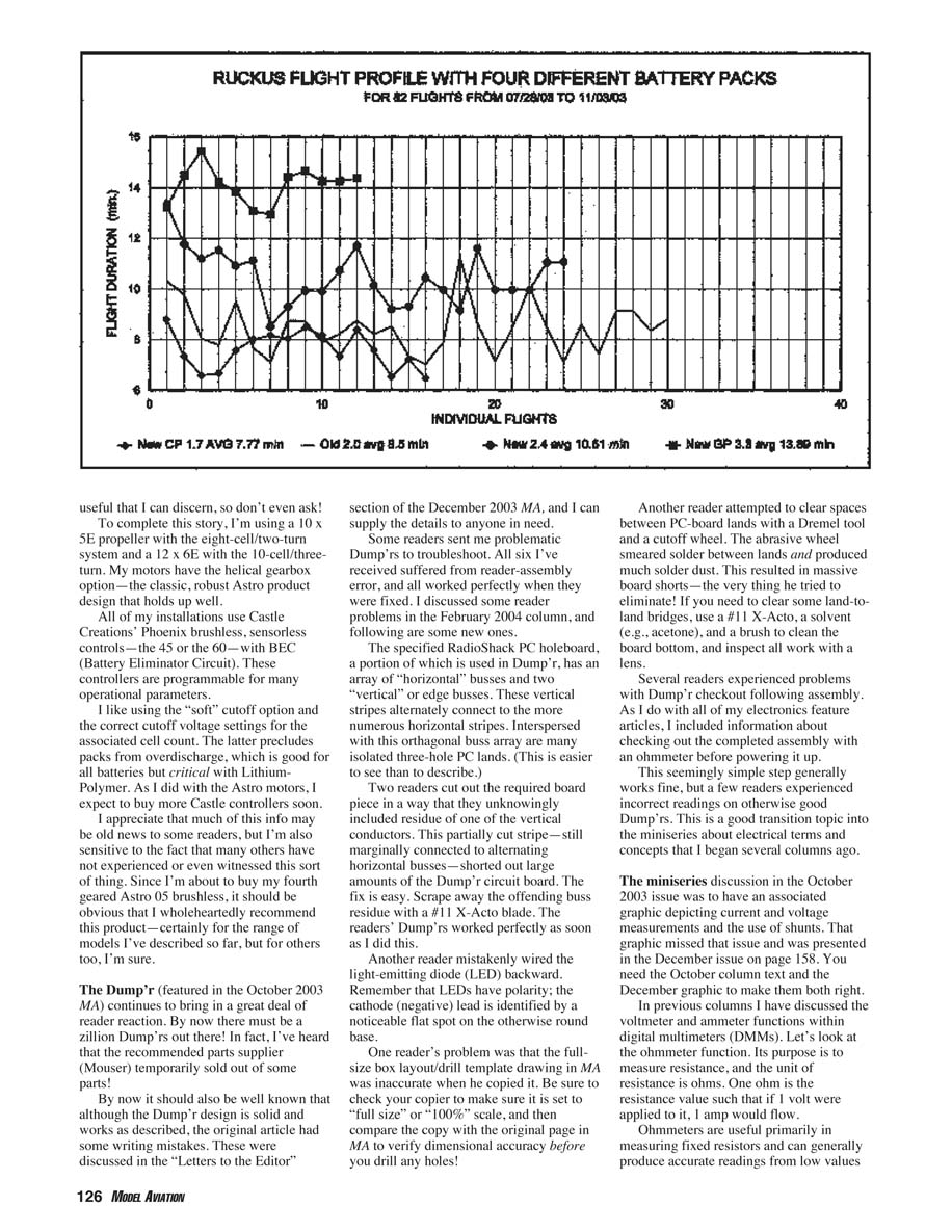
All my installations use Castle Creations’ Phoenix brushless sensorless controllers (the 45 or the 60) with BEC. These controllers are programmable for many operational parameters. I like using the “soft” cutoff option and the correct settings for good throttle response and pack protection. For those wondering about motor direction, the Astro brushless connector set makes reversing direction easy: rotate the connector by 180°.
I expect to buy more Castle controllers because their programmability (especially cutoff options) helps prevent overdischarge—important for all batteries and critical for Lithium-Polymer packs.
Dump’r reader feedback and troubleshooting
The Dump’r (featured in the October 2003 MA) continues to bring in a great deal of reader reaction. By now there must be a zillion Dump’rs out there; in fact, Mouser temporarily sold out of some recommended parts.
Although the Dump’r design is solid and works as described, the original article had some writing mistakes. Those were discussed in the “Letters to the Editor” section of the December 2003 MA; I can supply the details to anyone who needs them.
I have received several problematic Dump’rs for troubleshooting. All six I received suffered from reader-assembly errors and worked perfectly once fixed. Common problems and fixes:
- Residue of a vertical bus left on the RadioShack PC holeboard
- The PC holeboard has an array of horizontal busses and two vertical (edge) busses; the vertical stripes alternately connect to the horizontal stripes. Two readers cut the required board piece in a way that left residue of a vertical conductor. That partially cut stripe still connected to alternating horizontal busses and shorted the Dump’r board.
- Fix: scrape away the offending buss residue with a #11 X-Acto blade. The unit worked perfectly after cleaning.
- LED wired backward
- LEDs are polarized. The cathode (negative) lead is identified by a noticeable flat spot on the otherwise round base.
- Fix: reverse LED polarity.
- Incorrectly copied drill-template layout
- One reader’s full-size box layout/drill-template in MA was inaccurate because his copier was not set to 100% scale.
- Fix: set copier to “full size” or “100%” and compare the copy to the original page before drilling.
- Dremel/cutoff wheel damage
- One reader used a Dremel cutoff wheel to clear spaces between PC lands. The abrasive smeared solder and produced solder dust, resulting in massive shorts.
- Fix: use a #11 X-Acto, solvent (e.g., acetone), and a brush to clean, then inspect with magnification.
- Checkout problems with ohmmeters after assembly
- I included ohmmeter-based checkout instructions with the original article. Some readers saw incorrect readings on otherwise good Dump’r boards. See the Ohmmeter section below for guidance.
When checking Dump’r boards, many readers saw low-resistance values between lands they expected to be open. Often this was due to solder bridges or flux residue. Clean the board thoroughly and inspect under magnification.
Ohmmeters and DMM use (miniseries continuation)
The miniseries on electrical terms and concepts began months ago. The October 2003 issue’s discussion was supposed to include a graphic about current and voltage measurements and shunts; that graphic missed October and was presented in the December issue (page 158). You need the October column text plus the December graphic for the whole story.
A brief primer on the ohmmeter function of digital multimeters (DMMs):
- Purpose and unit
- An ohmmeter measures resistance; the unit is ohms (Ω). One ohm is the resistance that allows 1 amp to flow when 1 volt is applied.
- How DMMs measure resistance
- Most DMMs pass a small internal-battery-supplied current through the unknown resistance and measure the resulting voltage. Because the meter supplies the test current, remove power from the circuit before measuring resistance. Leaving power connected will give false readings and can damage the meter.
- Ranges and small resistance techniques
- DMMs have various ranges or auto-range. Many measure down to 0.1 ohm or lower, but small resistances require special techniques. Readings include meter lead resistance and contact resistance.
- To compensate: use the meter’s “zero” or “relative” function, or short the leads, note the reading, and subtract it from your measurement.
- Negative or strange readings
- Apparent negative resistance readings can occur when the circuit contains semiconductor junctions or active components that respond to the meter’s test current.
- Fixes: isolate the component, remove power, or desolder a lead to measure the component out of circuit.
- Temperature effects
- Resistor values can be temperature dependent. High current through a resistor can heat it and change resistance during measurement. Use the correct range and measure quickly.
- Diode-check vs continuity
- Diode-check mode shows the forward voltage drop of a diode, not its resistance. Continuity (beep) indicates a low-resistance path. Misinterpreting these modes can cause confusion. Use diode-check mode to verify forward drop, and continuity mode for simple short checks.
- In-circuit measurements
- In-circuit ohmmeter readings are often meaningless due to parallel paths. Best practice: measure isolated components or lift one end of the resistor/lead to avoid parallel circuits.
If readers would like, I can expand on measuring with DMMs, using current clamps, shunts, and energy meters in a future column.
Closing
If you have comments, questions, or experiences to share, please write. Include a self-addressed, stamped envelope if you want a reply; I do not use e-mail for this purpose.
Transcribed from original scans by AI. Minor OCR errors may remain.

