

RADIO CONTROL ELECTRICS
Bob Kopski, 25 West End Dr., Lansdale PA 19446
Electric Connection Service (ECS)
THIS COLUMN INCLUDES an Electric Connection Service (ECS) request, a Lithium-Polymer (Li-Poly) battery advisory, a receiver-problem advisory, an application for the Astro 05 brushless motor, a simple test for power-system noise effects, and one potential product announcement!
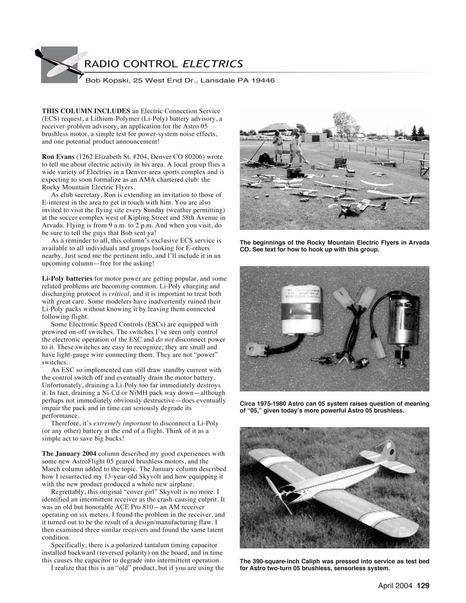
Ron Evans (1262 Elizabeth St. #204, Denver CO 80206) wrote to tell me about electric activity in his area. A local group flies a wide variety of Electrics in a Denver-area sports complex and is expecting to soon formalize as an AMA-chartered club: the Rocky Mountain Electric Flyers.
As club secretary, Ron is extending an invitation to those interested in Electrics in the area to get in touch with him. You are also invited to visit the flying site every Sunday (weather permitting) at the soccer complex west of Kipling Street and 58th Avenue in Arvada. Flying is from 9 a.m. to 2 p.m. And when you visit, do be sure to tell the guys that Bob sent you!
As a reminder to all, this column’s exclusive ECS service is available to all individuals and groups looking for other Electric fliers nearby. Just send me the pertinent info, and I’ll include it in an upcoming column—free for the asking!
Li-Poly Battery Advisory
Li-Poly batteries for motor power are getting popular, and some related problems are becoming common. Li-Poly charging and discharging protocol is critical, and it is important to treat both with great care. Some modelers have inadvertently ruined their Li-Poly packs without knowing it by leaving them connected following flight.
Some Electronic Speed Controls (ESCs) are equipped with prewired on-off switches. The switches I’ve seen only control the electronic operation of the ESC and do not disconnect power to it. These switches are easy to recognize; they are small and have light-gauge wire connecting them. They are not “power” switches. An ESC so implemented can still draw standby current with the control switch off and eventually drain the motor battery.
Unfortunately, draining a Li-Poly too far immediately destroys it. In fact, draining a Ni-Cd or NiMH pack way down—although perhaps not immediately obviously destructive—does eventually impair the pack and in time can seriously degrade its performance. Therefore, it’s extremely important to disconnect a Li-Poly (or any other) battery at the end of a flight. Think of it as a simple act to save big bucks!
Receiver-Problem Advisory (ACE Pro 810)
The January 2004 column described my good experiences with some new AstroFlight 05 geared brushless motors, and the March column added to the topic. The January column described how I resurrected my 13-year-old Skyvolt and how equipping it with the new product produced a whole new airplane.
Regrettably, this original “cover girl” Skyvolt is no more. I identified an intermittent receiver as the crash-causing culprit. It was an old but honorable ACE Pro 810—an AM receiver operating on six meters. I found the problem in the receiver, and it turned out to be the result of a design/manufacturing flaw. I then examined three similar receivers and found the same latent condition.
Specifically, there is a polarized tantalum timing capacitor installed backward (reversed polarity) on the board, and in time this causes the capacitor to degrade into intermittent operation. I realize that this is an “old” product, but if you are using the ACE Pro 810 AM receiver, you may encounter this situation. If you are interested, write to me and I’ll expand on the specifics, including how to fix it. Meanwhile, I’m flying my repaired receivers with renewed, solid performance. (The same problem occurs with the same-design, same-vintage receivers.)
AstroFlight 05 Brushless Application
As previously described, the Skyvolt was equipped with a two-turn AstroFlight geared brushless, sensorless motor on eight 2400s. The resulting performance, with a 10 x 5E propeller, was spectacular—vastly superior to any earlier power system used in that model.
The January column suggested that this power system could make new airplanes out of similar-sized models from that earlier time, such as the Mirage, the PT Electric, the AeroLectric, and others. Having lost the Skyvolt, I went digging through my inventory.
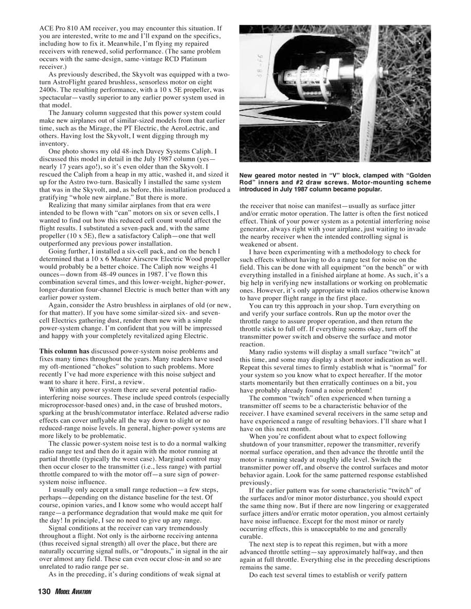
One photo shows my old 48-inch Davey Systems Caliph. I discussed this model in detail in the July 1987 column (yes—nearly 17 years ago!), so it's even older than the Skyvolt. I rescued the Caliph from a heap in my attic, washed it, and sized it up for the Astro two-turn. Basically I installed the same system that was in the Skyvolt, and, as before, this installation produced a gratifying "whole new airplane."
Realizing that many similar airplanes from that era were intended to be flown with "can" motors on six or seven cells, I wanted to find out how this reduced cell count would affect the flight results. I substituted a seven-pack and, with the same propeller (10 x 5E), flew a satisfactory Caliph—one that well outperformed any previous power installation.
Going further, I installed a six-cell pack, and on the bench I determined that a 10 x 6 Master Airscrew Electric Wood propeller would probably be a better choice. The Caliph now weighs 41 ounces—down from 48–49 ounces in 1987. I've flown this combination several times, and this lower-weight, higher-power, longer-duration four-channel Electric is much better than with any earlier power systems.
Again, consider the Astro brushless in airplanes of old (or new, for that matter). If you have some similar-sized six- and seven-cell Electrics gathering dust, render them new with a simple power-system change. I'm confident that you will be impressed and happy with your completely revitalized aging Electric.
Power-System Noise: Review and Simple Bench Test
This column has discussed power-system noise problems and fixes many times throughout the years. Many readers have used my oft-mentioned "chokes" solution to such problems. More recently I've had more experience with this noise subject and want to share it here. First, a review.
Within any power system there are several potential radio-interfering noise sources. These include speed controls (especially microprocessor-based ones), and, in the case of brushed motors, sparking at the brush/commutator interface. Related adverse radio effects can cover unflyable all the way down to slight or no reduced-range noise levels. In general, higher-power systems are more likely to be problematic.
The classic power-system noise test is to do a normal walking radio range test and then do it again with the motor running at partial throttle (typically the worst case). Marginal control may then occur closer to the transmitter (i.e., less range) with partial throttle compared to with the motor off—a sure sign of power-system noise influence.
I usually only accept a small range reduction—a few steps, perhaps—depending on the distance baseline for the test. Of course, opinion varies, and I know some who would accept half range—a performance degradation that would make me quit for the day! In principle, I see no need to give up any range.
Signal conditions at the receiver can vary tremendously throughout a flight. Not only is the airborne receiving antenna (thus received signal strength) all over the place, but there are naturally occurring signal nulls, or "dropouts," in signal in the air over almost any field. These can even occur close-in and so are unrelated to radio range per se.
As in the preceding, it's during conditions of weak signal at the receiver that noise can manifest—usually as surface jitter and/or erratic motor operation. The latter is often the first noticed effect. Think of your power system as a potential interfering noise generator, always right with your airplane, just waiting to invade the nearby receiver when the intended controlling signal is weakened or absent.
I have been experimenting with a methodology to check for such effects without having to do a range test at the field. This can be done with all equipment "on the bench" or with everything installed in a finished airplane at home. As such, it's a big help in verifying new installations or working on problematic ones. However, it's only appropriate with radios otherwise known to have proper flight range in the first place.
Bench-test procedure:
- Turn everything on and verify surface controls.
- Run up the motor over the throttle range to assure proper operation, then return the throttle stick to full off.
- If everything seems okay, turn off the transmitter power switch and observe the surface and motor reaction.
- Repeat several times to establish what is "normal" for your system.
Many radio systems will display a small surface "twitch" at this time, and some may display a short motor indication as well. Repeat this several times to firmly establish what is "normal" for your system so you know what to expect hereafter. If the motor starts momentarily but then erratically continues on a bit, you have probably already found a noise problem!
When you're confident about what to expect following a shutdown of your transmitter, repower the transmitter, reverify normal surface operation, and then advance the throttle until the motor is running steadily at roughly idle level. Switch the transmitter power off, and observe the control surfaces and motor behavior again. Look for the same patterned response established previously.
If the earlier pattern was for some characteristic "twitch" of the surfaces and/or minor motor disturbance, you should expect the same thing now. But if there are now lingering or exaggerated surface jitters and/or erratic motor operation, you almost certainly have noise influence. Except for the most minor or rarely occurring effects, this is unacceptable to me and generally curable.
Next steps and variations:
- Repeat the regimen at about halfway throttle and at full throttle. Do each test several times to establish or verify pattern repeatability.
- Repeat with the antenna disconnected.
- Repeat with ferrite chokes installed on the motor and battery leads. If the chokes help, you have identified a power-system noise source.
- On the bench you may also attempt to reduce the problem by moving the ESC and receiver apart, rotating the receiver, shortening antenna length, shielding leads, and trying different connectors.
- If none of these steps help, a small capacitor across the motor leads (and sometimes an inline resistor) has been used to reduce brush spark and motor noise; consult your ESC manufacturer before adding capacitors with brushless systems.
- Some readers report that certain propeller/motor combinations generate less noise and that careful twisting of motor and battery leads can help.
In short, there are several straightforward troubleshooting steps that can identify and often cure power-system noise.
Potential Product Announcement
Great news! The October 2003 column described what I believe is a much-needed electric product: ESCs with BECs (Battery Eliminator Circuits) of "switch mode" design so that even "high cell count" power systems could shed the normal radio-system battery.
At least one such ESC design is "in the mill," but I have no more to offer at this time. Stay tuned. I can't wait, because such a product is long overdue!
So ends another column. Here's wishing you many happy springtime (or anytime!) E-landings!
Please do enclose a self-addressed, stamped envelope with any correspondence for which you'd like a reply. Everyone so doing does get one.
MA
Transcribed from original scans by AI. Minor OCR errors may remain.

