

RADIO CONTROL ELECTRICS
Bob Kopski 25 West End Dr., Lansdale PA 19446
This column includes two meet announcements; reminds you of one good, long-running E-site; discusses two common reader issues; and continues the discussion of power-system / radio-noise issues that I initiated last month.
Meet announcements
- Burlington County RC Club (BCRCC) Electric Meet
- Date: Saturday, June 19, 2004
- Location: BCRCC Hedding Road Flying Field
- Contact: Bob Afflerback, 123 Harrington Cir., Willingboro NJ 08046; Tel.: (609) 871-8777
- Notes: Established affair dating to the late 1980s; low-key, friendly gathering. Bob is the contact and Tony Rossi is the contest director. Ask Bob for details and mention you heard about it here.
- Jersey Coast Sport Fliers Electric Fly-In
- Date: Saturday, July 17, 2004 (Sunday, July 18 rain date)
- Location: Large grass strip at Dorbrook Park, Colts Neck, New Jersey
- Contact: Rob Kallok, [email protected]
- Club site: www.jcsportfliers.org
- Flying scheduled from 10 a.m. until 7 p.m.
Useful E-power site
One of the longest-running electric-flight sites is run by Ken Myers at http://members.aol.com/kmyersefo. Ken is president of Electric Flyers Only, Inc. (a Michigan-based E-group) and editor of Ampeer, the club’s monthly newsletter. Ampeer is like a mini E-magazine and is available for $10 per year. Typical content includes reader-contributed discussion of E-products, technical offerings, and meet observations. The site archives contain several years’ worth of Ampeer articles. For those without Internet access, Ken’s address is: 1911 Bradshaw Ct., Walled Lake MI 48390 (Tel.: (248) 669-8124).
Reader issues: article copies and photos
Two frequently encountered reader issues are requests for article copies and photo submissions for this column.
- Article copies: I am not able to supply article copies directly. Article copies are available from AMA at low cost, and AMA’s archives are accessible online (best with a high-speed connection).
- Photos: I do like to receive reader photos and often include some in this column. Guidelines:
- Preferred: original 4 x 6-inch color glossies.
- Sometimes smaller prints work, but do not send printouts from digital cameras—MA cannot work with digitally printed photos even if they look good.
- Do not write on the back of photos.
- Turn off the camera time/date stamp.
- If you want a reply, please include an SASE.
Power-system noise: test setup and observations
In last month's column I discussed a methodology for easily checking power-system noise effects in the shop. Here I continue with additional specifics about receiver behavior I’ve observed.
Test setup (bench fixturing)
- An eight-cell brushless, sensorless power system is mounted in a compartmented enclosure (metal shielding covers removed for viewing in photos).
- Right compartment: motor, battery, and ESC. ESC cable runs through a separating wall to the left side.
- Left compartment: inductive link from the ESC cable to a coaxial port, a stub antenna input to the same port, and a local "servo driver" RC pulse generator powered from the ESC BEC. The servo driver operates the ESC/motor via a front-panel control knob.
- The coaxial output port is cabled to a Spectrum Analyzer (SA).
Purpose
- Observe, in a controlled and repeatable fashion, any RF noise present on an ESC/receiver cable.
- The setup includes a known noisy ESC for illustrative purposes.
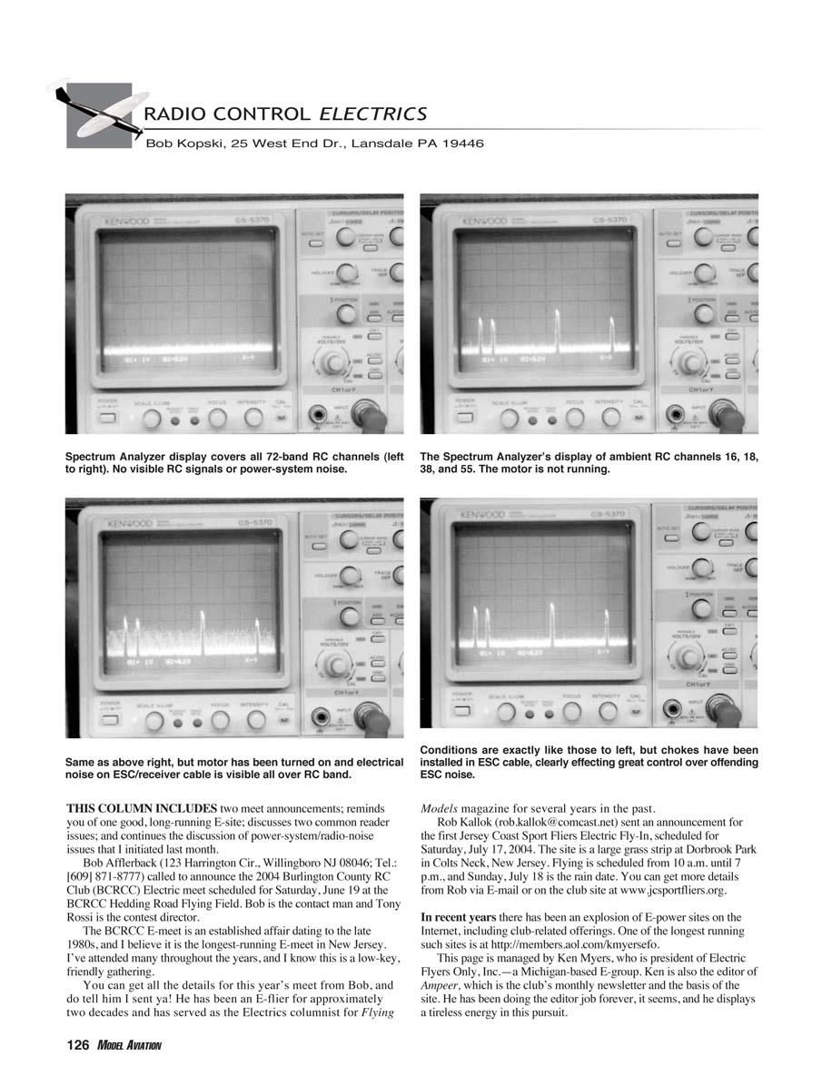
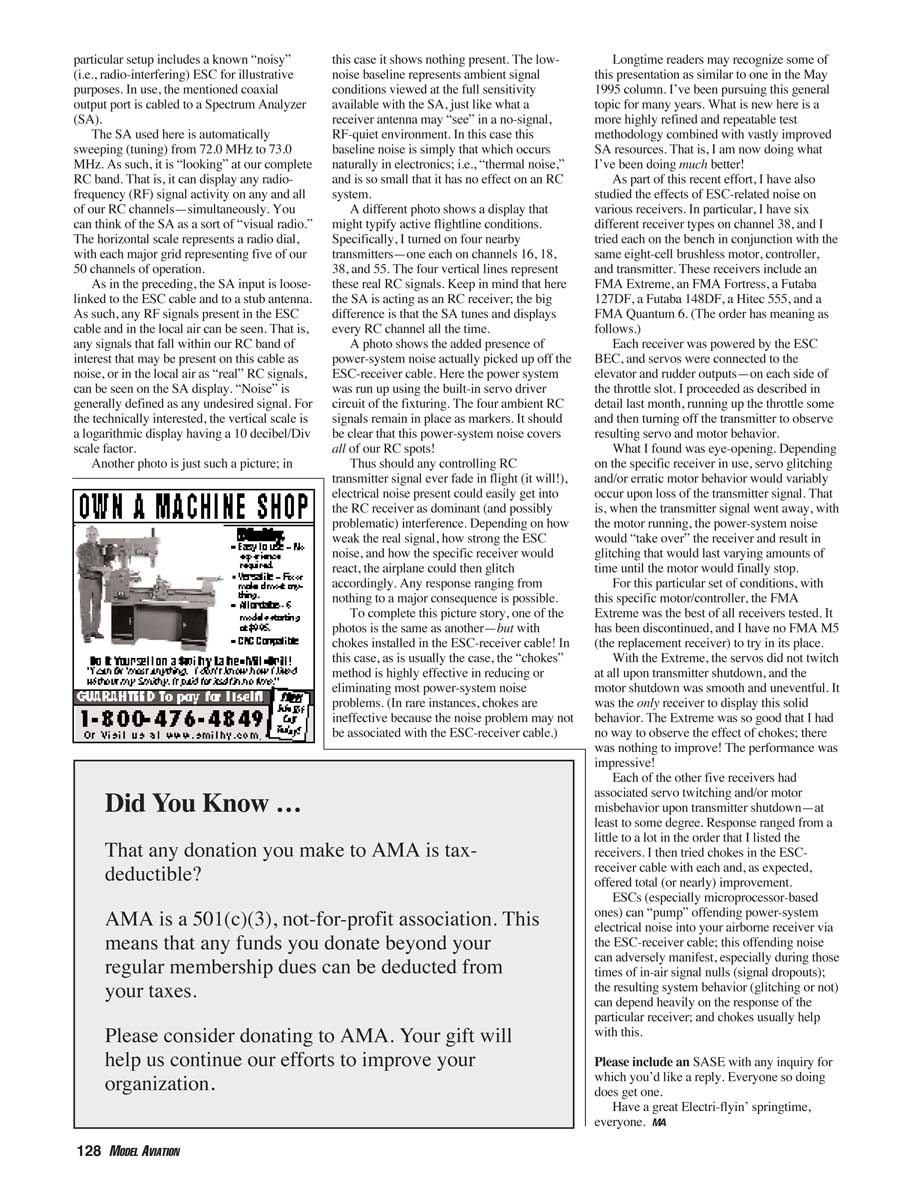
Spectrum Analyzer (SA) use
- The SA automatically sweeps from 72.0 MHz to 73.0 MHz, covering the RC band of interest.
- It displays any RF activity on all RC channels simultaneously; think of it as a "visual radio."
- The horizontal scale represents the radio dial; the vertical scale is logarithmic (10 dB/div).
SA observations
- Low-noise baseline: shows ambient signal conditions at full SA sensitivity—essentially thermal noise that has no effect on an RC system.
- Active flightline example: turning on four nearby transmitters (channels 16, 18, 38, and 55) produces four vertical lines representing real RC signals.
- Power-system noise example: running the motor with the noisy ESC produces a broad noise trace picked up from the ESC-receiver cable that covers many RC channels.
- With chokes installed in the ESC-receiver cable, the noise is usually greatly reduced or eliminated. (In rare cases, chokes are ineffective if the noise source is not associated with the ESC-receiver cable.)
Implication
- If a controlling RC transmitter signal ever fades in flight (it will), ESC-generated electrical noise present on the receiver power/cable can become dominant and cause receiver glitching. The severity depends on the relative signal strength, the ESC noise level, and the particular receiver’s susceptibility.
Receiver behavior tests
I tested six different receiver types on channel 38 with the same eight-cell brushless motor, controller, and transmitter. Each receiver was powered by the ESC BEC, and servos were connected to elevator and rudder outputs (on each side of the throttle slot). Procedure: run up the throttle and then turn off the transmitter to observe servo and motor behavior.
Receivers tested (in test order)
- FMA Extreme
- FMA Fortress
- Futaba 12ZDF
- Futaba 14G
- Hitec 555
- FMA Quantum 6
Results
- The FMA Extreme performed best: upon transmitter shutdown with the motor running, servos did not twitch and motor shutdown was smooth and uneventful. The Extreme was the only receiver to show this level of immunity. (Note: the Extreme has been discontinued; I did not have an FMA M5 to test as a replacement.)
- The other five receivers exhibited varying degrees of servo twitching and/or motor misbehavior when the transmitter signal was removed. The severity tended to follow the test order listed above (from better to worse).
- Adding chokes to the ESC-receiver cable provided total or nearly total improvement for these receivers in most cases.
Conclusions
- ESCs, especially microprocessor-based ones, can inject electrical noise into the airborne receiver via the ESC-receiver cable.
- During brief transmitter signal nulls, this noise can be interpreted by the receiver and manifest as glitching or erratic behavior.
- The degree of effect depends heavily on the receiver’s design and susceptibility.
- Chokes in the ESC-receiver cable are usually effective at reducing or eliminating the problem.
Please include an SASE with any inquiry for which you'd like a reply. Everyone so doing does get one.
Have a great Electri-flyin' springtime, everyone. MA
Transcribed from original scans by AI. Minor OCR errors may remain.

