
RADIO CONTROL ELECTRICS
Bob Kopski, 25 West End Dr., Lansdale PA 19446
THIS COLUMN INCLUDES a review of ESC motor (voltage) cutoff and some discussion of the Goldberg Tiger ARF.
Motor (Voltage) Cutoff — history and guidance
Based on reader mail, it's clear there is some misunderstanding about the motor (voltage)-cutoff function found in most contemporary ESCs. Following is some background and present-day info on the subject.
In the earliest days of electric power, little was thought of—and much less done about—controlling motor power in flight. Roughly 30 years ago, many E-fliers just turned on a manual motor switch, launched, and flew until the Ni-Cd pack ran dry.
This simplistic approach eventually gave way to the servo-driven motor switch, where a standard servo was mechanically linked to an ordinary toggle (or similar) switch. At last—the motor could be radio-controlled! An enhanced variation used a multiple-switch configuration to control a motor circuit resistor in one or more steps, and rudimentary "speed control" was born.
Everyone agrees that early electric power was a comparatively weak performer with short flights. Therefore, early focus was on stretching flight time as much as possible. This natural desire for one more go-round automatically led to well-drained packs at the end of each flight. It was not always realized that deep discharge was actually detrimental to Ni-Cd battery health.
The explanation is that when a battery of several cells is drained all the way, some cells may deplete ahead of others, and those are then subject to "reverse charge." This means the longer-lasting cells of a pack continue to supply current to the motor through those already dead ones, and the latter may thereby be driven "backward," or become reverse charged. This puts them at risk, and repeated use gradually causes cell damage.
Somewhere near the mid-1980s, MA presented an ESC construction article by Joe Utasi. To the best of my knowledge, this was a first. One could smoothly vary a motor's speed in flight from full off to full on. Joe later went into the business of manufacturing speed controls under the brand name JOMAR.
These earliest controllers, by virtue of a quirk in circuit behavior, caused the motor to sputter and rapidly lose power as a pack depleted to roughly 6.0 volts. This encouraged pilots to land, and in many cases this saved packs from cell reversal—especially the then-popular seven-cell pack. However, larger cell-count packs still had cells that were subject to reverse-charge damage.
Since it usually required numerous deep-discharge flights before degrading battery performance was noticed, the specific cause and effect were not always obvious. It took years before this was widely realized and accepted, and the delay resulted in many damaged Ni-Cd packs in those earlier days. But seven- (or eight-) cell packs under JOMAR control lasted longer—a clue for the future.
Fast-forward roughly a decade. Many more aeromodelers and suppliers had emerged on the electric scene, and a new kind of ESC appeared—ones with BEC. This Battery Eliminator Circuit, a feature added to the basic ESC, permitted the radio gear to be powered from the motor battery. This was a big deal; the receiver battery could be eliminated, and the weight savings were welcome.
But BEC quickly brought to the forefront another importance of not running a motor pack all the way down: to do so also meant loss of radio. "Rekitting" was rampant! Now there were two good reasons not to drain a motor pack all the way.
Aeromodelers were quick to address the latter problem, and BEC-equipped ESCs with "motor cutoff" began to appear. These ESCs had circuitry that would automatically shut down motor power as the pack depleted, to conserve some power for radio operation and safe landing. Clearly, this was a step in the right direction.
Somewhere along the way, an adjustable-voltage cutoff began to appear. This new feature permitted users to choose where during motor-battery rundown the actual motor cutoff would occur.
A guideline began to win favor: set the cutoff to occur at the Ni-Cd pack equivalent voltage of 0.9 volt per cell. So if you had a 10-cell pack, the ESC might be adjusted for motor shutdown to occur at a pack voltage of 9.0 volts.
The nominal 0.9 V-per-cell value would preclude cell reversal and early battery failure for the typical motor pack, provided all cells were reasonably matched. Furthermore, this guideline would typically assure continuing radio operation for safe landing where BEC was used. It was a twofer.
Although much of the preceding evolution happened during the dominant reign of Ni-Cd power in E-aeromodeling, the same guidelines were extended to NiMH as that battery technology emerged.
This brings us to now, and the latest battery for electric power: Li-Poly. Just a few years past introduction and rapidly growing in popularity, Li-Poly has mandated an even newer voltage-cutoff standard.
Mandated? Yes. Historic Ni-Cd and NiMH batteries could eventually be damaged by repeated deep discharge, but Li-Poly batteries may be destroyed by just one incident.
The magic number is 2.5 volts per cell for Li-Poly, although a more conservative 3.0 volts per cell is gaining popularity. So rundown must cease at least 7.5 volts for a three-cell Li-Poly pack, but I use the 9.0-volt number for added margin.
Remember that with just one overdischarge the Li-Poly is likely dead. So, as before, voltage cutoff of motor operation is mandated. This brings us to the latest ESCs: those that automatically set their cutoff values by first sensing how many cells are connected.
This feature is primarily aimed at Li-Poly-powered systems to help assure a safe operating environment for these packs. However, it also sets up a generally suitable cutoff value for Ni-Cd and NiMH systems. Hence the user need not manually program a proper voltage-cutoff value, which mostly eliminates the chance of operator error.
To summarize, it is advisable to have ESCs with a suitable voltage (motor)-cutoff function for two reasons:
- To prevent overdischarging the motor battery. This is imperative with Li-Poly-powered systems and extremely beneficial with Ni-Cd and NiMH.
- For BEC installations, to assure adequate remaining power for continuing radio operation and safe landing after the motor is shut down.
For most commonly used cell counts, the first reason generally assures the second. Motor control has certainly come a long way in 35 years!
Goldberg Tiger ARF — checkout and modifications
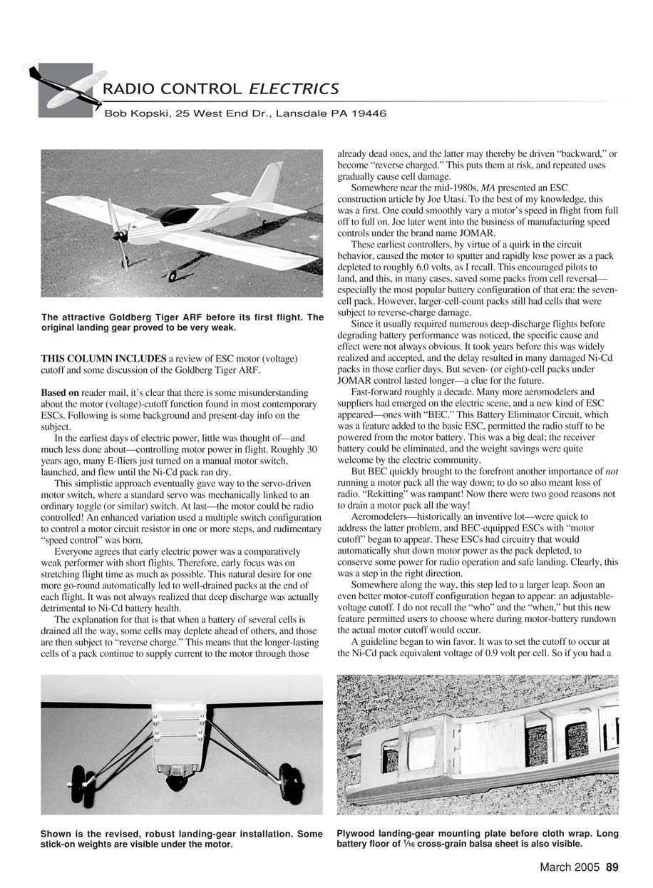
A local E-aeromodeler asked for assistance with his new Goldberg Tiger. It is an attractive Speed 400-class ARF, and he wanted a checkout and a test flight before he took the controls. Several things came out of this experience that are worth passing on.
The Tiger is a low-wing design which, for the most part, dictates a rise-off-ground (ROG) takeoff. It is challenging to hold a transmitter in one hand and safely hand-launch a low-winger with the other. The ROG requirement dictates other needs, such as a suitable surface, adequate power, and reasonable ground handling and control.
As with all new airplanes, it's prudent to check balance first. This Tiger was tail-heavy, and a reasonable solution was to move the seven-cell 500 AR pack far forward. This necessitated modifying the inner fuselage structure to include a battery floor extending through the LE former—which had to be cut out to some extent. This modification proved valuable later.
Accessing the replaceable pack was made easier by changing the screwed-on canopy to a rapid-access type. The front edge of the canopy was "toed in" to an added plastic holder piece in front and held in place with two foreshortened nylon landing-gear straps in the rear. These could be swung out of the way to slip the canopy off and access the pack.
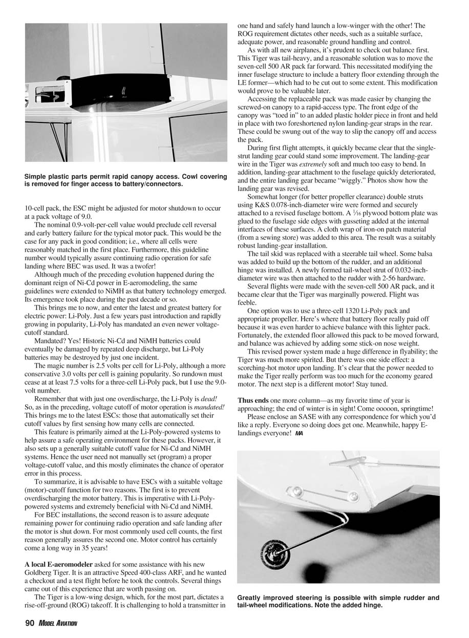
During first flight attempts, it quickly became clear that the single-strut landing gear could stand some improvement. The landing-gear wire in the Tiger was extremely soft and much too easy to bend. In addition, landing-gear attachment to the fuselage quickly deteriorated, and the entire landing gear became "wiggly."
Improvements made:
- Formed somewhat longer double struts (for better propeller clearance) using K&S 0.078-inch-diameter wire and securely attached them to a revised fuselage bottom.
- Glued a 1/16-inch plywood bottom plate to the fuselage side edges and added gusseting at the internal interfaces.
- Added a cloth wrap of iron-on patch material (from a sewing store) to reinforce the area.
The result was a suitably robust landing-gear installation.
The tail skid was replaced with a steerable tail wheel. Some balsa was added to build up the bottom of the rudder, and an additional hinge was installed. A newly formed tail-wheel strut of 0.032-inch-diameter wire was attached to the rudder with 2-56 hardware.
Several flights were made with the seven-cell 500 AR pack, and it became clear that the Tiger was marginally powered. Flight was feeble.
One option was to use a three-cell 1320 Li-Poly pack and the appropriate propeller. Here's where that battery floor really paid off because it was even harder to achieve balance with this lighter pack. Fortunately, the extended floor allowed this pack to be moved forward, and balance was achieved by adding some stick-on nose weight.
This revised power system made a huge difference in flyability; the Tiger was much more spirited. But there was one side effect: a scorching-hot motor upon landing. It's clear the power needed to make the Tiger really perform was too much for the economy geared motor. The next step is a different motor. Stay tuned.
Closing
Thus ends one more column—as my favorite time of year is approaching: the end of winter is in sight! Come oooooon, springtime!
Please enclose an SASE with any correspondence for which you'd like a reply. Everyone so doing does get one. Meanwhile, happy E-landings everyone! MA
Transcribed from original scans by AI. Minor OCR errors may remain.

