
RADIO CONTROL GIANTS - 2004/09
Sal Calvagna 1335 Broadway Ave., Holbrook NY 11741 E-mail: [email protected]
I'm so excited about our latest project that I want to share it with you. I have been infatuated with RC Giants for approximately 20 years. In that time I have built models from kits and plans, I scratch-built from three-views, and even put together a couple of Giant ARFs. Imagine my joy when I actually became involved with designing a Giant Scale model for manufacture.
During the past nine months I have been working with Larry Sribnick, the president of SR Batteries, designing a 1/4-scale Fokker Eindecker E.I. Larry is well known for his outstanding designs such as the X250, Cutie, and AcroPro model kits. We were able to take some of the innovative design features of these smaller models along with the experience I have with gas-powered models and apply them to a 100-inch wingspan, 16-pound World War I fighter.
One of the first lessons that I had to learn was patience. It may have only taken a couple of months to construct a one-off aircraft for myself, but designing and building a model as a product for others to build is quite a different task. Plans needed to be drawn, exact-fitting balsa and light-plywood parts had to be made, and an easy-to-follow, descriptive instruction manual had to be written.
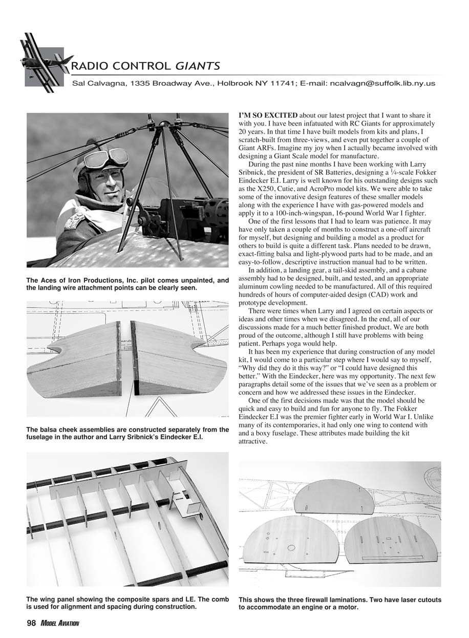
In addition, a landing gear, a tail-skid assembly, and a cabane assembly had to be designed, built, and tested, and an appropriate aluminum cowling needed to be manufactured. All of this required hundreds of hours of computer-aided design (CAD) work and prototype development.
There were times when Larry and I agreed on certain aspects or ideas and other times when we disagreed. In the end, all of our discussions made for a much better finished product. We are both proud of the outcome, although I still have problems with being patient. Perhaps yoga would help.
It has been my experience that during construction of any model kit, I would come to a particular step where I would say to myself, "Why did they do it this way?" or "I could have designed this better." With the Eindecker, here was my opportunity. The next few paragraphs detail some of the issues that we've seen as a problem or concern and how we addressed these issues in the Eindecker.
One of the first decisions made was that the model should be quick and easy to build and fun for anyone to fly. The Fokker Eindecker E.I was the premier fighter early in World War I. Unlike many of its contemporaries, it had only one wing to contend with and a boxy fuselage. These attributes made building the kit attractive.
The full-scale Eindecker used wing warping and a full-flying stabilizer and rudder. We used a more traditional approach and incorporated ailerons and elevators; however, we kept the full-flying rudder. At 100 inches, the model can be entered in any of the International Miniature Aircraft Association events including the popular warbird categories.
Manufacturing Process
To maintain exact tolerances, we believed the best method of design and manufacture was CAD and micro laser-cutting. This process ensures accurately fitting parts and became critical with the composite spar and leading-edge (LE) design chosen for the Eindecker wings.
Power System
Usually a model is designed with electric, gas, or glow as the power plant of choice. We decided early in the process that the model would be dual-powered for gas or glow (wet) or electric (dry). We specifically designed the kit to accommodate both systems. We chose the Zenoah G-26 for the gas-powered version and the AXI 4130/20 brushless motor for the electric power system. Both power the same 18 x 6 propeller.
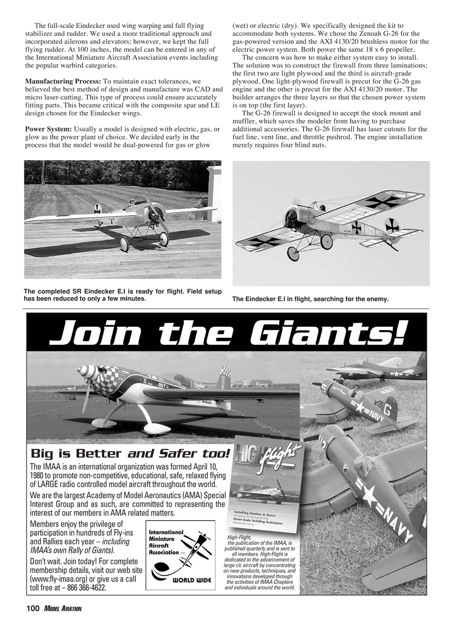
The concern was how to make either system easy to install. The solution was to construct the firewall from three laminations: the first two are light plywood and the third is aircraft-grade plywood. One light-plywood firewall is precut for the G-26 gas engine and the other is precut for the AXI 4130/20 motor. The builder arranges the three layers so that the chosen power system is on top (the first layer).
The G-26 firewall is designed to accept the stock mount and muffler, which saves the modeler from having to purchase additional accessories. The G-26 firewall has laser cutouts for the fuel line, vent line, and throttle pushrod. The engine installation merely requires four blind nuts.
Wing Assembly
Having built and sanded many Giant Scale wings, I found it time-consuming and difficult to make round and true leading edges. In addition, with the natural tendency of wood spars to warp, sometimes it is hard to build a straight wing.
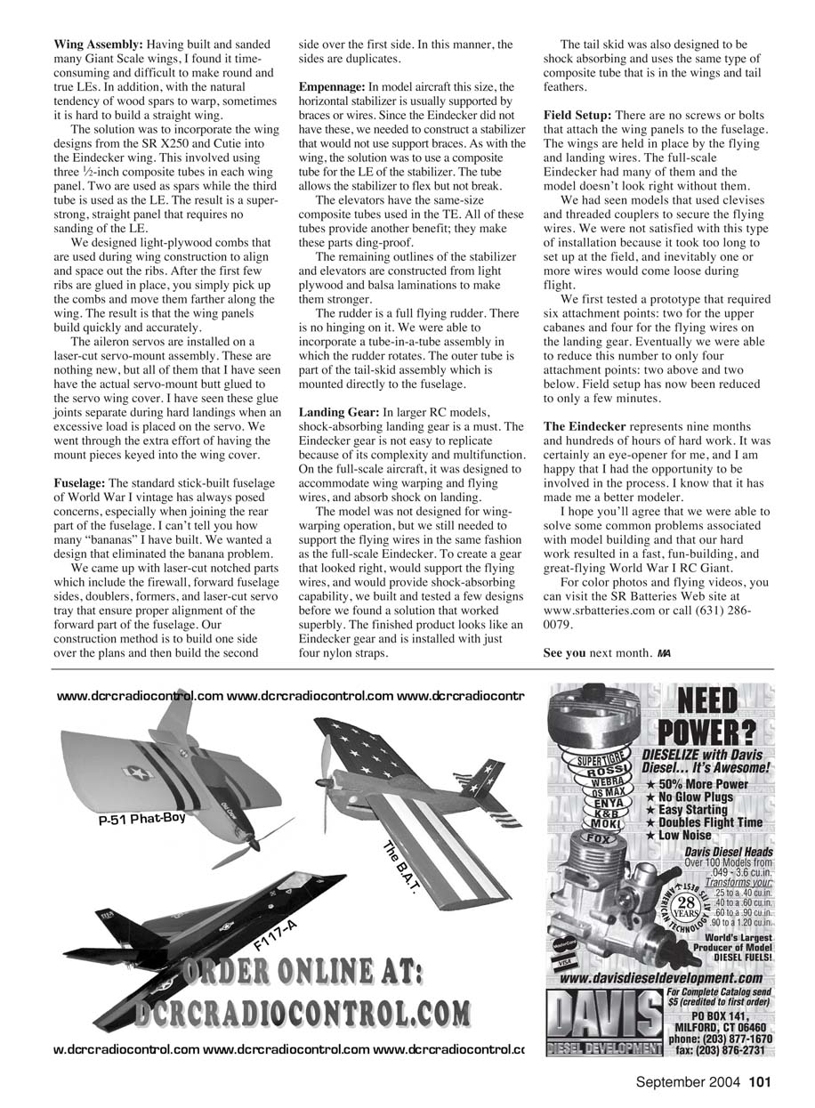
The solution was to incorporate the wing designs from the SR X250 and Cutie into the Eindecker wing. This involved using three 1/2-inch composite tubes in each wing panel. Two are used as spars while the third tube is used as the LE. The result is a super-strong, straight panel that requires no sanding of the LE.
We designed light-plywood combs that are used during wing construction to align and space out the ribs. After the first few ribs are glued in place, you simply pick up the combs and move them farther along the wing. The result is that the wing panels build quickly and accurately.
The aileron servos are installed on a laser-cut servo-mount assembly. These are nothing new, but all of the ones I have seen have the actual servo-mount glued to the servo wing cover. I have seen these glue joints separate during hard landings when an excessive load is placed on the servo. We went through the extra effort of having the mount pieces keyed into the wing cover.
Fuselage
The standard stick-built fuselage of World War I vintage has always posed concerns, especially when joining the rear part of the fuselage. I can’t tell you how many "bananas" I have built. We wanted a design that eliminated the banana problem.
We came up with laser-cut notched parts which include the firewall, forward-fuselage sides, doublers, formers, and a laser-cut servo tray that ensure proper alignment of the forward part of the fuselage. Our construction method is to build one side over the plans and then build the second side over the first side. In this manner, the sides are duplicates.
Empennage
In model aircraft this size, the horizontal stabilizer is usually supported by braces or wires. Since the Eindecker did not have these, we needed to construct a stabilizer that would not use support braces. As with the wing, the solution was to use a composite tube for the LE of the stabilizer. The tube allows the stabilizer to flex but not break.
The elevators have the same-size composite tubes used in the trailing edge (TE). All of these tubes provide another benefit: they make these parts ding-proof.
The remaining outlines of the stabilizer and elevators are constructed from light plywood and balsa laminations to make them stronger.
The rudder is a full-flying rudder. There is no hinging on it. We were able to incorporate a tube-in-a-tube assembly in which the rudder rotates. The outer tube is part of the tail-skid assembly which is mounted directly to the fuselage.
Landing Gear
In larger RC models, shock-absorbing landing gear is a must. The Eindecker gear is not easy to replicate because of its complexity and multifunction. On the full-scale aircraft, it was designed to accommodate wing warping and flying wires, and absorb shock on landing.
The model was not designed for wing-warping operation, but we still needed to support the flying wires in the same fashion as the full-scale Eindecker. To create a gear that looked right, would support the flying wires, and would provide shock-absorbing capability, we built and tested a few designs before we found a solution that worked well. The finished product looks like an Eindecker gear and is installed with just four nylon straps.
The tail skid was also designed to be shock absorbing and uses the same type of composite tube that is in the wings and tail feathers.
Field Setup
There are no screws or bolts that attach the wing panels to the fuselage. The wings are held in place by the flying and landing wires. The full-scale Eindecker had many of them and the model doesn't look right without them.
We had seen models that used clevises and threaded couplers to secure the flying wires. We were not satisfied with this type of installation because it took too long to set up at the field, and inevitably one or more wires would come loose during flight.
We first tested a prototype that required six attachment points: two for the upper cabanes and four for the flying wires on the landing gear. Eventually we were able to reduce this number to only four attachment points: two above and two below. Field setup has now been reduced to only a few minutes.
The Eindecker represents nine months and hundreds of hours of hard work. It was certainly an eye-opener for me, and I am happy that I had the opportunity to be involved in the process. I know that it has made me a better modeler.
I hope you'll agree that we were able to solve some common problems associated with model building and that our hard work resulted in a fast, fun-building, and great-flying World War I RC Giant.
For color photos and flying videos, or to visit the SR Batteries Web site, go to www.srbatteries.com or call (631) 286-0079.
See you next month. MA
Transcribed from original scans by AI. Minor OCR errors may remain.

